Page 2125 of 5267
3. Carefully position retainer/oil seal (1) to block.
Tighten the retainer bolts to 11 Nꞏm (95 in. lbs.).
4. Install flywheel and clutch (Refer to 6 - CLUTCH/
CLUTCH DISC - INSTALLATION).
5. Install transmission (Refer to 21 - TRANSMISSION/
TRANSAXLE/MANUAL - INSTALLATION).
Page 2134 of 5267
BEARING-CRANKSHAFT PILOT
REMOVAL
1. Remove transmission (Refer to 21 - TRANSMIS-
SION/TRANSAXLE/MANUAL - REMOVAL).
2. Remove clutch and flywheel (Refer to 6 - CLUTCH/
CLUTCH DISC - REMOVAL).
3. Using Special Tools 8990 (1) and C-3752 (2),
remove pilot bearing from crankshaft.
INSTALLATION
NOTE: New pilot bearing has special grease
packed into bearing. Do not wash grease from
bearing. Install bearing with part number markings
(1) facing out.
Page 2135 of 5267
1. Install pilot bearing with Special Tools 9058 (1) and
C-4171 (2).
2. Install flywheel and clutch (Refer to 6 - CLUTCH/
CLUTCH DISC - INSTALLATION).
3. Install transmission (Refer to 21 - TRANSMISSION/
TRANSAXLE/MANUAL - INSTALLATION).
Page 2503 of 5267
7. Disconnect A/C clutch coil wire connector (2).
8. Remove return hose from radiator fan at power steering pump reservoir.
9. Remove return hose from fluid cooler at power steering pump reservoir.
10. Remove three bolts mounting power steering
pump (5) to engine.
11. Remove power steering pump.
12. If required, transfer necessary parts from removed
power steering pump to replacement power steer-
ing pump. (Refer to 19 - STEERING/PUMP -
DISASSEMBLY).
Page 2504 of 5267

INSTALLATION
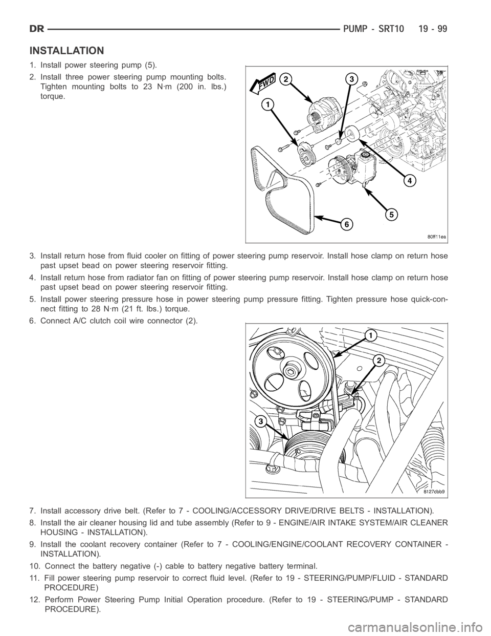
1. Install power steering pump (5).
2. Install three power steering pump mounting bolts.
Tighten mounting bolts to 23 Nꞏm (200 in. lbs.)
torque.
3. Install return hose from fluid cooler on fitting of power steering pump reservoir. Install hose clamp on return hose
past upset bead on power steering reservoir fitting.
4. Install return hose from radiator fan on fitting of power steering pump reservoir. Install hose clamp on return hose
past upset bead on power steering reservoir fitting.
5. Install power steering pressure hose in power steering pump pressure fitting. Tighten pressure hose quick-con-
nect fitting to 28 Nꞏm (21 ft. lbs.) torque.
6. Connect A/C clutch coil wire connector (2).
7. Install accessory drive belt. (Refer to 7 - COOLING/ACCESSORY DRIVE/DRIVE BELTS - INSTALLATION).
8. Install the air cleaner housing lid and tube assembly (Refer to 9 - ENGINE/AIR INTAKE SYSTEM/AIR CLEANER
HOUSING - INSTALLATION).
9. Install the coolant recovery container (Refer to 7 - COOLING/ENGINE/COOLANT RECOVERY CONTAINER -
INSTALLATION).
10. Connect the battery negative (-) cable to battery negative battery terminal.
11. Fill power steering pump reservoir to correct fluid level. (Refer to 19- STEERING/PUMP/FLUID - STANDARD
PROCEDURE)
12. Perform Power Steering Pump Initial Operation procedure. (Refer to 19- STEERING/PUMP - STANDARD
PROCEDURE).
Page 2523 of 5267

MANUAL TRANSMISSION - G56 - SERVICE INFORMATION
DIAGNOSIS AND TESTING
MANUAL TRANSMISSION - G56
LOW LUBRICANT LEVEL
A low transmission lubricant level is generally the result of a leak, inadequate lubricant fill or incorrect lubricant level
check.
Rear transmission leakswill be from the oil seals or component mating surfaces.
Front transmission leakswill be from the front input shaft retainer seal. Lubricant may drip from theclutchhousing
after extended operation. If leak is severe, it may contaminate the clutchdisc.
Lubricant level checkcan only be made when the vehicle is level and allowing the lubricant to settle for a minute
before checking. This will ensure an accurate check and avoid an under or overfill condition.
HARD SHIFTING
Hard shifting is usually caused by low lubricant level, improper or contaminated lubricants. This will cause noise,
excessive wear, internal bind, and hard shifting. Substantial lubricantleaks can result in gear, shift rail, synchro, and
bearing damage. The first indications of component damage is usually hardshifting and noise.
Shift component damage, clutch adjustment, worn pressure plate or disc are also causes of increased shift effort. If
clutch problem is advanced, gear clash during shifts can result. Worn or damaged synchronizer rings can cause
gear clash when shifting into any forward gear. In some new or rebuilt transmissions, new synchro rings may tend
to stick slightly causing hard or noisy shifts. In most cases, this condition will decline as the rings wear-in.
TRANSMISSION NOISE
Most manual transmissions make some noise during normal operation. Rotating gears generate a mild whine that is
audible, but generally only at extreme speeds.
Severe, highly audible transmission noise is generally the initial indicator of a lubricant problem. Insufficient,
improper or contaminated lubricant will promote rapid wear of gears, synchronizer rings, shift rails, forks and bear-
ings. The overheating caused by a lubricant problem, can also lead to gear and bearing damage.
Page 2527 of 5267
14. Remove structural dust cover (1) clutch housing
bolts (2) and dust shield bolts (3) on 5.7L engine.
CAUTION: On 5.7L engine do not remove struc-
tural dust cover from engine block. If cover is
removed clutch housing and structural dust cover
must be aligned with the engine.
15. Remove exhaust bracket (1) bolts and remove
bracket on diesel engine.
Page 2528 of 5267
16. Support engine with adjustable jack stand and
wood block.
17. Support and secure transmission (1) to a trans-
mission jack (2) with safety chains.
18. Remove transmission mount bolts (1).
19. Remove rear crossmember bolts (2) and remove
crossmember with transmission mount.
20. Remove exhaust Y-pipe on 5.7L engine.
21. Remove bolts attaching transmission to the
engine.
22. Move transmission rearward until input shaft is
clear of clutch disc and pressure plate. Then
lower jack and remove transmission from under
vehicle.