Page 2710 of 5267
39. Install offset lever (3) roll pin with hammer (1) and
punch (2)..
40. Install Mopar
Gasket Maker to the shift cover
sealing surface and position cover on the trans-
mission.
41. Install shift cover four mounting bolts and tighten
to 18 Nꞏm (13 ft. lbs.).
INSTALLATION
1. Slide transmission back into the clutch and seat
against clutch housing.
2. Install transmission bolts to clutch housing bolts
and tighten to and tighten bolts to 35 Nꞏm (26 ft.
lbs.)
3. Install transmission crossmember (2) and bolts/nuts
(1).Tightennutsto61Nꞏm(45ft.lbs.).
4. Install transmission mount (2) bolts (1) and tighten
to 41 Nꞏm (30 ft. lbs.).
5. Remove transmission jack.
Page 2711 of 5267
6. Install back up lamp switch (2) connector (1).
7. Install fuel line to top plate stud.
8. Install reverse lockout solenoid (1) harness connec-
tor (2).
9. Install hydraulic clutch quick connector (1) to the
slave cylinder.
10. Clean transmission shifter tower sealing surfaces
and apply a bead of Mopar
Gasket Maker.
11. Install shifter tower and tighten bolts to 18 Nꞏm
(156 in. lbs.).
12. Install propeller shaft with reference marks
aligned.
CAUTION: The drive shaft strap bolts must be
replaced or cleaned and Loctite
242 applied.
CAUTION: Replace drive shaft joint straps when-
ever they are removed. The straps slightly deform
when torqued in place. Reuse of the straps may
result in reduced clamp load on the universal joint
cap.
Page 2713 of 5267
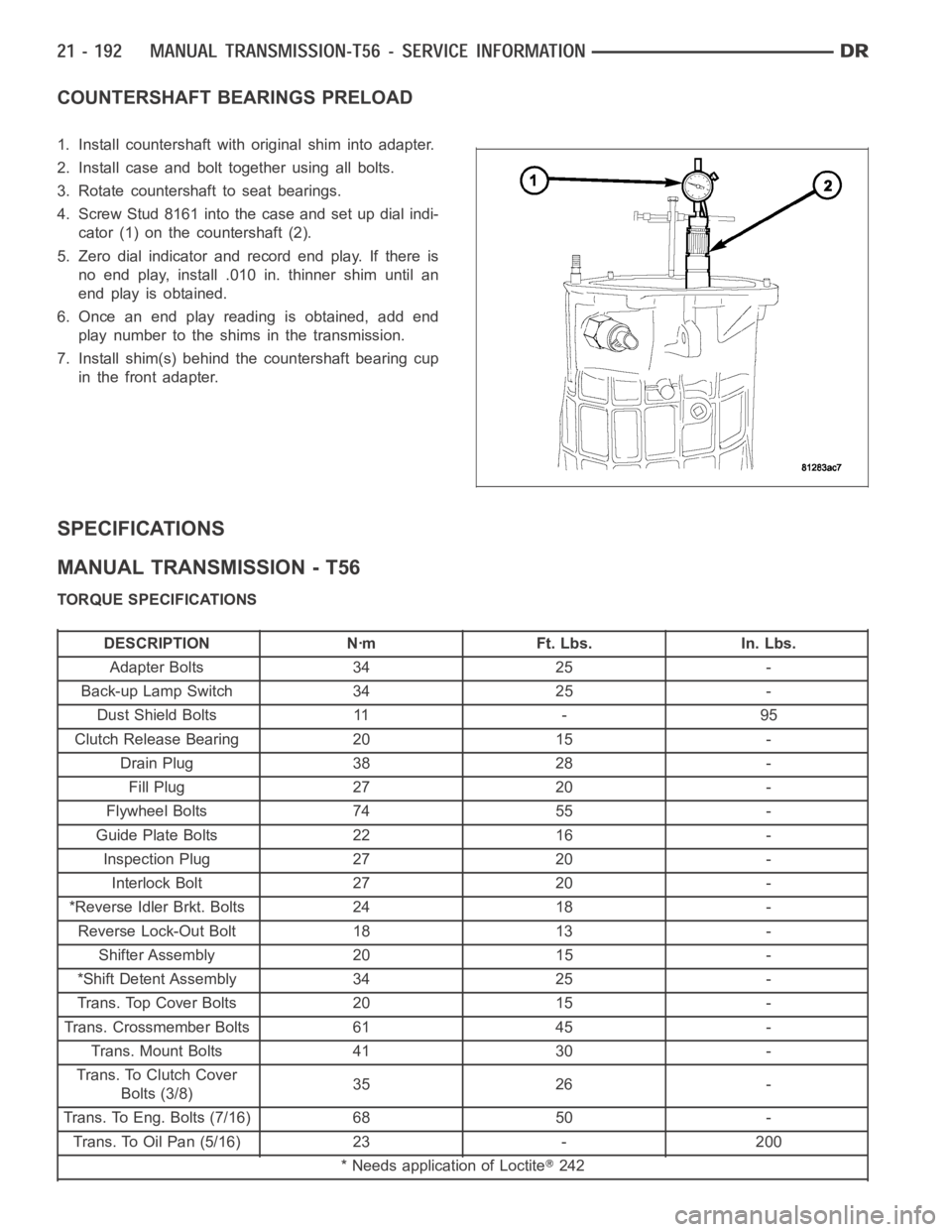
COUNTERSHAFT BEARINGS PRELOAD
1. Install countershaft with original shim into adapter.
2. Install case and bolt together using all bolts.
3. Rotate countershaft to seat bearings.
4. Screw Stud 8161 into the case and set up dial indi-
cator (1) on the countershaft (2).
5. Zero dial indicator and record end play. If there is
no end play, install .010 in. thinner shim until an
end play is obtained.
6. Once an end play reading is obtained, add end
play number to the shims in the transmission.
7. Install shim(s) behind the countershaft bearing cup
in the front adapter.
SPECIFICATIONS
MANUAL TRANSMISSION - T56
TORQUE SPECIFICATIONS
DESCRIPTION Nꞏm Ft. Lbs. In. Lbs.
Adapter Bolts 34 25 -
Back-up Lamp Switch 34 25 -
Dust Shield Bolts 11 - 95
Clutch Release Bearing 20 15 -
Drain Plug 38 28 -
Fill Plug 27 20 -
Flywheel Bolts 74 55 -
Guide Plate Bolts 22 16 -
Inspection Plug 27 20 -
Interlock Bolt 27 20 -
*Reverse Idler Brkt. Bolts 24 18 -
Reverse Lock-Out Bolt 18 13 -
Shifter Assembly 20 15 -
*Shift Detent Assembly 34 25 -
Trans. Top Cover Bolts 20 15 -
Trans. Crossmember Bolts 61 45 -
Trans. Mount Bolts 41 30 -
Trans. To Clutch Cover
Bolts (3/8)35 26 -
Trans. To Eng. Bolts (7/16) 68 50 -
Trans. To Oil Pan (5/16) 23 - 200
* Needs application of Loctite
242
Page 2720 of 5267
SHAFT-INPUT
REMOVAL
NOTE: If input shaft is damaged behind the seal,
the transmission must be disassembled and
inspected.
1. Remove transmission from the vehicle.
2. Measure output shaft end play and record number.
3. Remove clutch slave cylinder from transmission
adapter plate.
4. Remove front adapter plate bolts (1).
5. Pry front cover adapter loose.
6. Hold input shaft while removing adapter (2).
7. Remove sealant from transmission adapter.
8. Clean and inspect all sealing surfaces for wear or
damage.
9. Lift counter shaft slightly and remove input shaft (2)
from transmission (1).
Page 2771 of 5267
P0731-GEAR RATIO ERROR IN 1ST
For a complete wiring diagramRefer to Section 8W.
When Monitored:
The Transmission gear ratio is monitored continuously while the transmission is in gear.
Set Condition:
If the ratio of the Input RPM to the Output RPM does not match the current gearratio when compared to the
known gear ratio.
Possible Causes
RELATED TRANSMISSION DTCS PRESENT
INTERMITTENT GEAR RATIO ERRORS
INTERNAL TRANSMISSION
Always perform the 42RLE Pre-Diagnostic Troubleshooting procedure before proceeding. (Refer to 21 -
TRANSMISSION/TRANSAXLE/AUTOMATIC - 42RLE - STANDARD PROCEDURE)
Theory of Operation
The transmission system uses two speed sensors, one to measure input RPM and one to measure output RPM.
These inputs are essential for proper transmission operation. Therefore, the integrity of this data is verified through
data checks. When in gear, if the gear ratio does not compare to a known gear ratio, the corresponding gear ratio
error trouble code is set. The transmission will go into Limp-in mode afterfour gear ratio error events occur in a
given driving cycle.
Diagnostic Test
1.DETERMINING IF RELATED TRANSMISSION DTCS ARE PRESENT
With the scan tool, read Transmission DTCs.
If any of these DTCs are present, perform their respective tests first.
Are there any Loss of Prime, Line Pressure Sensor and/or Speed Sensor DTCs present?
Ye s>>
Refer to appropriate diagnostic procedure in the Transmission category.If any of these DTC’s are
present, they will cause a gear ratio error. Perform the test for Loss of Primefirstifitispresent.
No>>
Go To 2
2.CHECK TO SEE IF P0731 IS CURRENT
With the scan tool, perform the 1st gear clutch test. Follow the instructions on the scan tool.
Increase the throttle angle or TPS Degree to 30° for no more than a few seconds.
CAUTION: Do not overheat the transmission.
Did the Clutch Test pass, Input Speed remain at zero?
Ye s>>
Go To 3
No>>
Repair internal Transmission as necessary. Check all of the components relatedtotheUDandLR
clutches. Inspect the Oil Pump and repair or replace as necessary. Refer tothe Service Information for
the proper repair procedures.
Perform 42RLE TRANSMISSION VERIFICATION TEST - VER 1. (Refer to 21 - TRANSMISSION/
TRANSAXLE/AUTOMATIC - 42RLE - STANDARD PROCEDURE)
Page 2772 of 5267
3.CHECK FOR INTERMITTENT OPERATION
The conditions to set this DTC are not current at this time.
Check the gearshift linkage adjustment.
Gear ratio DTCs can be set by problems in the Input and Output Speed Sensor circuits. If the vehicle passes the
Clutch Test and still sets Gear Ratio DTC, check the Speed Sensors for proper operation.
Remove the Ignition Switch Feed fuse from the TIPM.
CAUTION: Removal of the Ignition Switch Feed fuse from the TIPM will prevent the vehicle from being
startedingear.
WARNING: The Ignition Switch Feed fuse must be removed from the TIPM. Failure to do so can result in
personal injury or death.
Install the Transmission Simulator,Miller tool #8333 and the ElectronicTransmission Adapter kit.
Check the wiring and connectors for the Speed Sensors for a good connection, then perform a wiggle test using the
Transmission Simulator.
This DTC can also be set under extreme temperature conditions. This is usually caused by an internal problem.
Verify if the problem is only experienced under extreme hot or cold conditions.
With the scan tool, check the DTC EVENT DATA to help identify the conditionsin which the DTC was set.
Check for Service Information Tune-ups or Service Bulletins for any possible causes that may apply.
Were there any problems found?
Ye s>>
Repair as necessary.
Perform 42RLE TRANSMISSION VERIFICATION TEST - VER 1. (Refer to 21 - TRANSMISSION/
TRANSAXLE/AUTOMATIC - 42RLE - STANDARD PROCEDURE)
No>>
Te s t C o m p l e t e .
Page 2773 of 5267
P0732-GEAR RATIO ERROR IN 2ND
For a complete wiring diagramRefer to Section 8W.
When Monitored:
The Transmission gear ratio is monitored continuously while the transmission is in gear.
Set Condition:
If the ratio of the Input RPM to the Output RPM does not match the current gearratio when compared to the
known gear ratio.
Possible Causes
RELATED TRANSMISSION DTCS PRESENT
TRANSMISSION SOLENOID/PRESSURE SWITCH ASSEMBLY
INTERMITTENT GEAR RATIO ERRORS
INTERNAL TRANSMISSION
Always perform the Pre-Diagnostic Troubleshooting procedure before proceeding. (Refer to 21 - TRANSMIS-
SION/TRANSAXLE/AUTOMATIC - 42RLE - STANDARD PROCEDURE)
Theory of Operation
The transmission system uses two speed sensors, one to measure input RPM and one to measure output RPM.
These inputs are essential for proper transmission operation. Therefore, the integrity of this data is verified through
data checks. When in gear, if the gear ratio does not compare to a known gear ratio, the corresponding gear ratio
error trouble code is set. The transmission will go into Limp-in mode afterfour gear ratio error events occur in a
given driving cycle.
Diagnostic Test
1.CHECK IF RELATED TRANSMISSION DTCS ARE PRESENT
With the scan tool, read Transmission DTCs.
If any of these DTCs are present, perform their respective tests first.
Are there any Loss of Prime, Line Pressure Sensor and/or Speed Sensor DTCs present?
Ye s>>
Refer to appropriate diagnostic procedure in the Transmission category.If any of these DTCs are
present, they will cause a gear ratio error. Perform the test for Loss of Primefirstifitispresent.
No>>
Go To 2
2.CHECK IF THE DTC IS CURRENT
With the scan tool, perform the 2nd gear clutch test. Follow the instructions on the scan tool.
Increase the throttle angle or TPS Degree to 30° for no more than a few seconds.
CAUTION: Do not overheat the transmission.
Did the Clutch Test pass, Input Speed remain at zero?
Ye s>>
Go To 3
No>>
Go To 4
Page 2774 of 5267
3.CHECK FOR INTERMITTENT OPERATION
The conditions to set this DTC are not current at this time.
Check the gearshift linkage adjustment.
Gear ratio DTCs can be set by problems in the Input and Output Speed Sensor circuits. If the vehicle passes the
Clutch Test and still sets Gear Ratio DTC, check the Speed Sensors for proper operation.
Remove the Ignition Switch Feed fuse from the TIPM.
CAUTION: Removal of the Ignition Switch Feed fuse from the TIPM will prevent the vehicle from being
startedingear.
WARNING: The Ignition Switch Feed fuse must be removed from the TIPM. Failure to do so can result in
personal injury or death.
Install the Transmission Simulator,Miller tool #8333 and the ElectronicTransmission Adapter kit.
Check the wiring and connectors to the Speed Sensors for a good connection,then perform a wiggle test using the
Transmission Simulator.
This DTC can also be set under extreme temperature conditions. This is usually caused by an internal problem.
Verify if the problem is only experienced under extreme hot or cold conditions.
With the scan tool, check the DTC EVENT DATA to help identify the conditionsin which the DTC was set.
Were there any problems found?
Ye s>>
Repair as necessary.
Perform 42RLE TRANSMISSION VERIFICATION TEST - VER 1. (Refer to 21 - TRANSMISSION/
TRANSAXLE/AUTOMATIC - 42RLE - STANDARD PROCEDURE)
No>>
Te s t C o m p l e t e .
4.CHECKFORRELATEDPRESSURESWITCHDTCS
With the scan tool, read Transmission DTC’s.
Are the DTCs P0845 and/or P0846 present also?
Ye s>>
Replace the Transmission Solenoid/Pressure Switch Assembly per the Service Information.
Perform 42RLE TRANSMISSION VERIFICATION TEST - VER 1. (Refer to 21 - TRANSMISSION/
TRANSAXLE/AUTOMATIC - 42RLE - STANDARD PROCEDURE)
No>>
Repair internal Transmission per the Service Information. Check all of the components related to the UD
and 2/4 clutches. Inspect the Oil Pump and repair or replace as necessary.
Perform 42RLE TRANSMISSION VERIFICATION TEST - VER 1. (Refer to 21 - TRANSMISSION/
TRANSAXLE/AUTOMATIC - 42RLE - STANDARD PROCEDURE)