2006 DODGE RAM SRT-10 clutch
[x] Cancel search: clutchPage 2883 of 5267
P1713-RESTRICTED MANUAL VALVE IN T2 RANGE
For a complete wiring diagramRefer to Section 8W
When Monitored:
Ignition on, engine running with the gear shift selector in a valid forwardgear.
Set Condition:
This DTC sets whenever Transmission control system detects the manual valve is in the T2 range when it
should be in OD. This is mainly an informational DTC.
Possible Causes
RELATED TRANSMISSION DTC’S PRESENT
CUSTOMER DRIVING HABITS
MIS-ADJUSTED SHIFTER CABLE
Always perform the Pre-Diagnostic Troubleshooting procedure before proceeding. (Refer to 21 - TRANSMIS-
SION/TRANSAXLE/AUTOMATIC - 42RLE - STANDARD PROCEDURE)
Diagnostic Test
1.DETERMINING IF RELATED DTC’S ARE PRESENT
With the scan tool, check for other transmission DTC’s
Are there any speed sensor or gear ratio DTCs present?
Ye s>>
Refer to the Transmission category and perform the appropriate symptom.
No>>
Go To 2
2.CHECK THE GEAR SHIFT CABLE FOR PROPER ADJUSTMENT
Check the Gear shift cable adjustment per the Service Information.
Also check the cable for possible binding or improperly routed.
Is the Gear shift cable properly adjusted and not binding or improperly routed?
Ye s>>
Go To 3
No>>
Adjust the Shifter Assembly per the Service Information.
Perform 42RLE TRANSMISSION VERIFICATION TEST - VER 1. (Refer to 21 - TRANSMISSION/
TRANSAXLE/AUTOMATIC - 42RLE - STANDARD PROCEDURE)
3.CHECK CUSTOMER DRIVING HABIT
This DTC can be set if the customer does not move the shift lever completely into the OD position (in between
gears) causing the manual valve to be in the T2 position.
When this occurs, the feed port to the clutch is restricted, the transmission will declare neutral, and this DTC will
set.
This DTC can also be set by simply bumping the shift lever toward neutral while accelerating.
With the scan tool, check the DTC EVENT DATA to help identify the conditionsin which the DTC was set.
If there are no possible causes remaining, view repair.
Repair
This DTC can be set by the shift lever inthe wrong position or not completelyin the OD position. Make
sure the customer is properly informed.
Perform 42RLE TRANSMISSION VERIFICATION TEST - VER 1. (Refer to 21 - TRANSMISSION/
TRANSAXLE/AUTOMATIC - 42RLE - STANDARD PROCEDURE)
Page 2886 of 5267
When Monitored:
Prior to a shift into 1st gear.
Set Condition:
Transmission temperature must be hot. DTC is set after six unsuccessful attempts to shift into 1st gear.
Possible Causes
RELATED DTC P0841 PRESENT
(T16) TRANSMISSION CONTROL OUTPUT CIRCUIT OPEN
(T50) L/R PRESSURE SWITCH SENSE CIRCUIT OPEN
(T50) L/R PRESSURE SWITCH SENSE CIRCUIT SHORT TO GROUND
(T50) L/R PRESSURE SWITCH SENSE CIRCUIT SHORT TO VOLTAGE
INTERNAL TRANSMISSION
POWERTRAIN CONTROL MODULE
Always perform the 42RLE Pre-Diagnostic Troubleshooting procedure before proceeding. (Refer to 21 -
TRANSMISSION/TRANSAXLE/AUTOMATIC - 42RLE - STANDARD PROCEDURE)
Theory of Operation
The Solenoid Switch Valve, an internal, hydraulically operated valve, controls the direction of the transmission fluid
when the LR solenoid is energized. When the solenoid switch valve is in the downshifted position and the LR sole-
noid is energized, fluid is directed to the LR element for 1st gear. When thesolenoid switch valve is In the up-
shifted position (2nd, 3rd, and 4th gear) and the LR solenoid is energized,fluidisdirectedintotheLockupSwitch
Valve which controls the Torque Converter Clutch. When shifting into 1st gear, a special sequence is followed to
insure solenoid switch valve movement into the downshifted position. TheLR pressure switch is monitored to con-
firm switch valve movement. If the solenoid switch valve movement is not confirmed (i.e. no LR pressure when the
LR solenoid is energized), 2nd gear is substituted for 1st. No 1st gear (2ndgear is substituted). The transmission
Torque converter FEMCC operation is inhibited. MIL on after 5 min. of substituted operation.
Diagnostic Test
1.DETERMINING IF RELATED DTCS ARE PRESENT
With the scan tool, check for other Transmission DTCs
Is the DTC P0841 present also?
Ye s>>
Refer to the Transmission category and perform the appropriate symptom.
No>>
Go To 2
2.CHECK TO SEE IF DTC P1775 IS CURRENT
With the scan tool, view DTCs.
Is the status Active for this DTC or is the STARTS SINCE SET counter 2 or less?
Ye s>>
Go To 3
No>>
Go To 8
Page 2891 of 5267
When Monitored:
Every 7 ms when doing PEMCC or FEMCC.
Set Condition:
Must be in partial or full EMCC. The DTC is set if L/R pressure is detected high for the fourth time.
Possible Causes
RELATED DTC P0841 PRESENT
DTC EVENT DATA SHOWS TRS CODE TR2 - SHIFT LEVER OR MANUAL CONTROL VALVE IN A INVA L I D
POSITION
SHIFTER CABLE OUT OF ADJUSTMENT
SOLENOID SWITCH VALVE STICKING IN ITS BORE
(T50) L/R PRESSURE SWITCH SENSE CIRCUIT OPEN
(T50) L/R PRESSURE SWITCH SENSE CIRCUIT SHORT TO GROUND
(T50) L/R PRESSURE SWITCH SENSE CIRCUIT SHORT TO VOLTAGE
VA LV E B O D Y
POWERTRAIN CONTROL MODULE
Always perform the Pre-Diagnostic Troubleshooting procedure before proceeding. (Refer to 21 - TRANSMIS-
SION/TRANSAXLE/AUTOMATIC - 42RLE - STANDARD PROCEDURE)
Theory of Operation
The Solenoid Switch Valve, an internal, hydraulically operated valve, controls the direction of the transmission fluid
when the L/R solenoid is energized. When the solenoid switch valve is in thedownshifted position and the L/R
solenoid is energized, fluid is directed to the L/R element for 1st gear. When the solenoid switch valve is In the
up-shifted position (2nd, 3rd, and 4th gear) and the L/R solenoid is energized, fluid is directed into the Lockup
Switch Valve which controls the Torque Converter Clutch. When doing PEMCCor FEMCC, the L/R pressure switch
should indicate no pressure if the solenoid switch valve is in the L/R position. If the L/R pressure switch indicates
pressure for some time while in partial or full EMCC, the EMCC operation is aborted and momentarily inhibited to
avoid accidental application of the L/R clutch. EMCC is attempted again when there is no L/R pressure. The fourth
detection of L/R pressure while in PEMCC or FEMCC will result in setting theDTC. Torque converter EMCC oper-
ation inhibited. MIL on after 5 min. of substituted operation.
Diagnostic Test
1.DETERMINING IF RELATED DTC’S ARE PRESENT
With the scan tool, check for other Transmission DTC’s
Is the DTC P0841 present also?
Ye s>>
Refer to the Transmission category and perform the appropriate symptom.
No>>
Go To 2
2.CHECK THE DTC EVENT DATA FOR TRS CODE TR2
With the scan tool, check the DTC EVENT DATA for P1776.
Does the DTC EVENT DATA show a TRS Code of TR2?
Ye s>>
This indicates the shift lever and the manual control valve were in an invalid position between Neutral
and OD. Check the shifter cable for: proper adjustment, binding, friction, improper routing, or the shifter
was moved in transit. Repair as necessary.
Perform 42RLE TRANSMISSION VERIFICATION TEST - VER 1. (Refer to 21 - TRANSMISSION/
TRANSAXLE/AUTOMATIC - 42RLE - STANDARD PROCEDURE)
No>>
Go To 3
Page 2908 of 5267
STANDARD PROCEDURE
PRE-DIAGNOSTIC TROUBLESHOOTING PROCEDURE - 42RLE
For a complete wiring diagramRefer to Section 8W.
1.
Perform the following steps prior to any diagnostic procedure:
Many transmission symptoms can be caused by a low fluid level. If the fluid level is low, locate and repair any
leaks and fill the transmission to the proper fluid level. Refer to the Service Information for the proper repair
and fluid fill procedures.
Testing should only be performed with the battery fully charged to avoid false diagnosis.
With the scan tool, read Engine (PCM) DTCs. If Engine DTCs are present, refer to the Driveability Category
and perform to the appropriate diagnostic procedure(s) before proceeding.
With the scan tool, read Transmission (TCM) DTCs. Record all Stored, Active, and Pending DTC information.
Diagnose any Pending DTC as a matured DTC.
With the scan tool, read DTC EVENT DATA.Use this data to identify the conditions in which the DTC was set.
Note: Performing a Battery Disconnect will clear all DTC EVENT DATA and reset all learned Transmis-
sion values to the controllers default values, which may temporarily result in erratic shift schedules.
With the scan tool, perform the Shift Lever Position Test. If the test does not pass, refer to the diagnostic
procedure for P0706-Check Shifter Signal.
For Gear Ratio Error DTCs, use the scan tool to read and record the Clutch Volume Index (CVI) information.
Use the wiring diagram as a guide, inspect the wiring and connectors related to this circuit and repair as nec-
essary.
Refer to the When Monitored and Set Conditions for this DTC. DTCs can set at ignition on, at start up, driving
under specific conditions, and after controller diagnostic monitors haverun.
Refer to applicable Technical Service Bulletins (TSBs) for controller software update information. Some condi-
tions can be corrected by upgrading the Engine (PCM) or Transmission (TCM)controller software.
Check for any Service Information Tune-ups or Service Bulletins for any possible causes that may apply.
Were there any repairs made that fixed the vehicle?
Ye s>>
Testing complete.
Perform 42RLE VERIFICATION TEST - VER1(Referto21-TRANSMISSION/TRANSAXLE/AUTO-
MATIC - 42RLE - STANDARD PROCEDURE)
No>>
Refer to the Transmission category and perform the appropriate diagnostic procedure(s). (Refer to 21 -
TRANSMISSION/TRANSAXLE/AUTOMATIC - 42RLE - DIAGNOSIS AND TESTING)
Page 2910 of 5267
page page
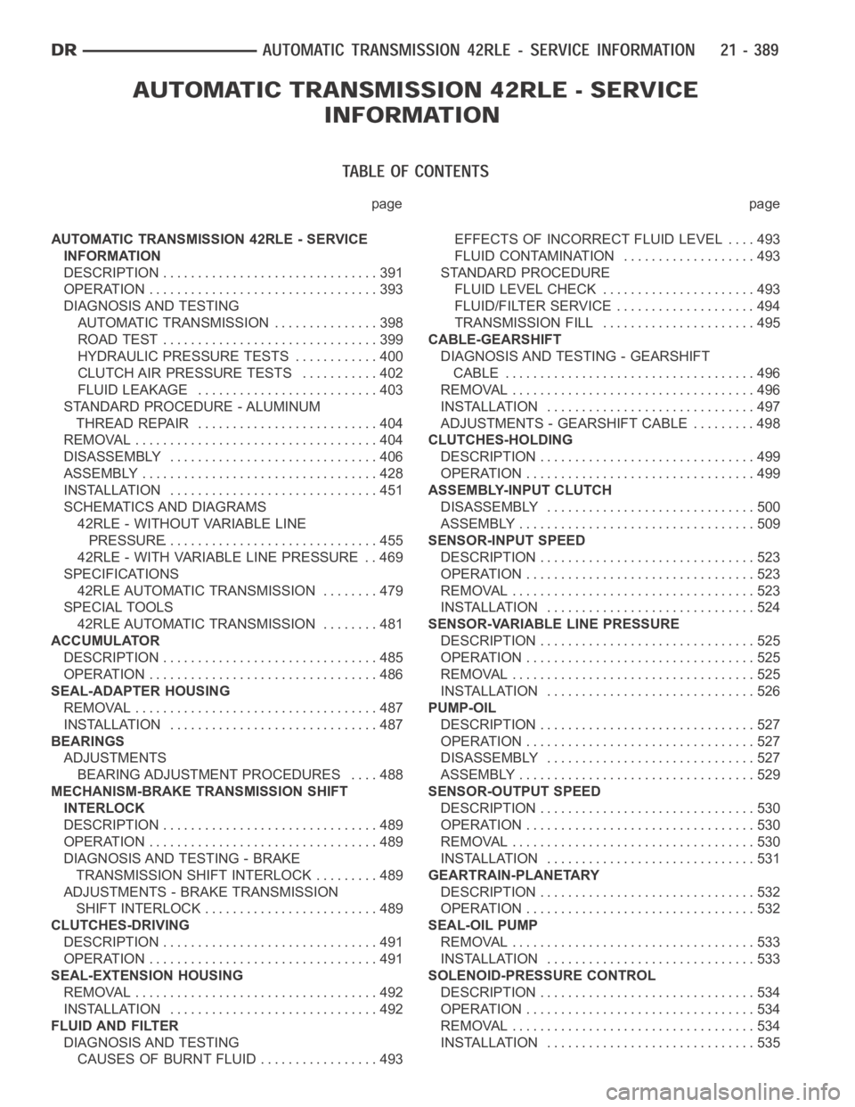
AUTOMATIC TRANSMISSION 42RLE - SERVICE
INFORMATION
DESCRIPTION ............................... 391
OPERATION ................................. 393
DIAGNOSIS AND TESTING
AUTOMATIC TRANSMISSION ............... 398
ROAD TEST ............................... 399
HYDRAULIC PRESSURE TESTS............ 400
CLUTCH AIR PRESSURE TESTS........... 402
FLUID LEAKAGE.......................... 403
STANDARD PROCEDURE - ALUMINUM
THREAD REPAIR .......................... 404
REMOVAL ................................... 404
DISASSEMBLY .............................. 406
ASSEMBLY .................................. 428
INSTALLATION .............................. 451
SCHEMATICS AND DIAGRAMS
42RLE - WITHOUT VARIABLE LINE
PRESSURE............................... 455
42RLE - WITH VARIABLE LINE PRESSURE . . 469
SPECIFICATIONS
42RLE AUTOMATIC TRANSMISSION ........ 479
SPECIAL TOOLS
42RLE AUTOMATIC TRANSMISSION ........ 481
ACCUMULATOR
DESCRIPTION ............................... 485
OPERATION ................................. 486
SEAL-ADAPTER HOUSING
REMOVAL ................................... 487
INSTALLATION .............................. 487
BEARINGS
ADJUSTMENTS
BEARING ADJUSTMENT PROCEDURES.... 488
MECHANISM-BRAKE TRANSMISSION SHIFT
INTERLOCK
DESCRIPTION ............................... 489
OPERATION ................................. 489
DIAGNOSIS AND TESTING - BRAKE
TRANSMISSION SHIFT INTERLOCK ......... 489
ADJUSTMENTS - BRAKE TRANSMISSION
SHIFT INTERLOCK ......................... 489
CLUTCHES-DRIVING
DESCRIPTION ............................... 491
OPERATION ................................. 491
SEAL-EXTENSION HOUSING
REMOVAL ................................... 492
INSTALLATION .............................. 492
FLUID AND FILTER
DIAGNOSIS AND TESTING
CAUSES OF BURNT FLUID ................. 493EFFECTS OF INCORRECT FLUID LEVEL . . . . 493
FLUID CONTAMINATION ................... 493
STANDARD PROCEDURE
FLUID LEVEL CHECK...................... 493
FLUID/FILTER SERVICE .................... 494
TRANSMISSION FILL ...................... 495
CABLE-GEARSHIFT
DIAGNOSIS AND TESTING - GEARSHIFT
CABLE .................................... 496
REMOVAL ................................... 496
INSTALLATION .............................. 497
ADJUSTMENTS - GEARSHIFT CABLE ......... 498
CLUTCHES-HOLDING
DESCRIPTION ............................... 499
OPERATION ................................. 499
ASSEMBLY-INPUT CLUTCH
DISASSEMBLY .............................. 500
ASSEMBLY .................................. 509
SENSOR-INPUT SPEED
DESCRIPTION ............................... 523
OPERATION ................................. 523
REMOVAL ................................... 523
INSTALLATION .............................. 524
SENSOR-VARIABLE LINE PRESSURE
DESCRIPTION ............................... 525
OPERATION ................................. 525
REMOVAL ................................... 525
INSTALLATION .............................. 526
PUMP-OIL
DESCRIPTION ............................... 527
OPERATION ................................. 527
DISASSEMBLY .............................. 527
ASSEMBLY .................................. 529
SENSOR-OUTPUT SPEED
DESCRIPTION ............................... 530
OPERATION ................................. 530
REMOVAL ................................... 530
INSTALLATION .............................. 531
GEARTRAIN-PLANETARY
DESCRIPTION ............................... 532
OPERATION ................................. 532
SEAL-OIL PUMP
REMOVAL ................................... 533
INSTALLATION .............................. 533
SOLENOID-PRESSURE CONTROL
DESCRIPTION ............................... 534
OPERATION ................................. 534
REMOVAL ................................... 534
INSTALLATION .............................. 535
Page 2914 of 5267
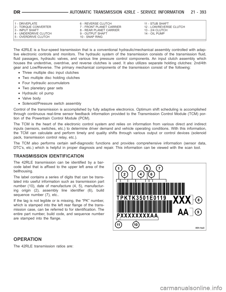
The 42RLE is a four-speed transmission that is a conventional hydraulic/mechanical assembly controlled with adap-
tive electronic controls and monitors. The hydraulic system of the transmission consists of the transmission fluid,
fluid passages, hydraulic valves, and various line pressure control components. An input clutch assembly which
houses the underdrive, overdrive, and reverse clutches is used. It also utilizes separate holding clutches: 2nd/4th
gear and Low/Reverse. The primary mechanical components of the transmission consist of the following:
Three multiple disc input clutches
Two multiple disc holding clutches
Four hydraulic accumulators
Two planetary gear sets
Hydraulic oil pump
Valve body
Solenoid/Pressure switch assembly
Control of the transmission is accomplished by fully adaptive electronics. Optimum shift scheduling is accomplished
through continuous real-time sensor feedback information provided to the Transmission Control Module (TCM) por-
tion of the Powertrain Control Module (PCM).
The TCM is the heart of the electronic control system and relies on information from various direct and indirect
inputs (sensors, switches, etc.) to determine driver demand and vehicle operating conditions. With this information,
the TCM can calculate and perform timely and quality shifts through various output or control devices (solenoid
pack, transmission control relay, etc.).
The TCM also performs certain self-diagnostic functions and provides comprehensive information (sensor data,
DTC’s, etc.) which is helpful in proper diagnosis and repair. This informationcanbeviewedwiththescantool.
TRANSMISSION IDENTIFICATION
The 42RLE transmission can be identified by a bar-
code label that is affixed to the upper left area of the
bellhousing.
The label contains a series of digits that can be trans-
lated into useful information such as transmission part
number (10), date of manufacture (4, 5), manufactur-
ing origin (2), assembly line identifier (6), build
sequence number (7), etc..
If the tag is not legible or is missing, the “PK” number,
which is stamped into the left rear flange of the trans-
mission case, can be referred to for identification. The
entire part number, build code, and sequence number
are stamped into the flange.
OPERATION
The 42RLE transmission ratios are:
1 - DRIVEPLATE 6 - REVERSE CLUTCH 11 - STUB SHAFT
2 - TORQUE CONVERTER 7 - FRONT PLANET CARRIER 12 - LOW/REVERSE CLUTCH
3 - INPUT SHAFT 8 - REAR PLANET CARRIER 13 - 2/4 CLUTCH
4 - UNDERDRIVE CLUTCH 9 - OUTPUT SHAFT 14 - OIL PUMP
5 - OVERDRIVE CLUTCH 10 - SNAP RING
Page 2915 of 5267
First 2.84 : 1
Second 1.57 : 1
Third 1.00 : 1
Overdrive 0.69 : 1
Reverse 2.21 : 1
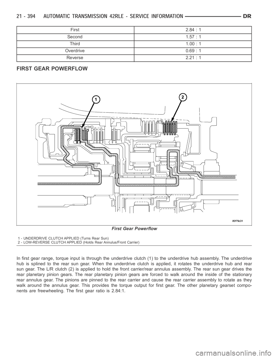
FIRST GEAR POWERFLOW
In first gear range, torque input is through the underdrive clutch (1) to the underdrive hub assembly. The underdrive
hub is splined to the rear sun gear. When the underdrive clutch is applied, it rotates the underdrive hub and rear
sun gear. The L/R clutch (2) is applied to hold the front carrier/rear annulus assembly. The rear sun gear drives the
rear planetary pinion gears. The rear planetary pinion gears are forced towalk around the inside of the stationary
rear annulus gear. The pinions are pinned to the rear carrier and cause the rear carrier assembly to rotate as they
walk around the annulus gear. This provides the torque output for first gear. The other planetary gearset compo-
nents are freewheeling. The first gear ratio is 2.84:1.
First Gear Powerflow
1 - UNDERDRIVE CLUTCH APPLIED (Turns Rear Sun)
2 - LOW-REVERSE CLUTCH APPLIED (Holds Rear Annulus/Front Carrier)
Page 2916 of 5267
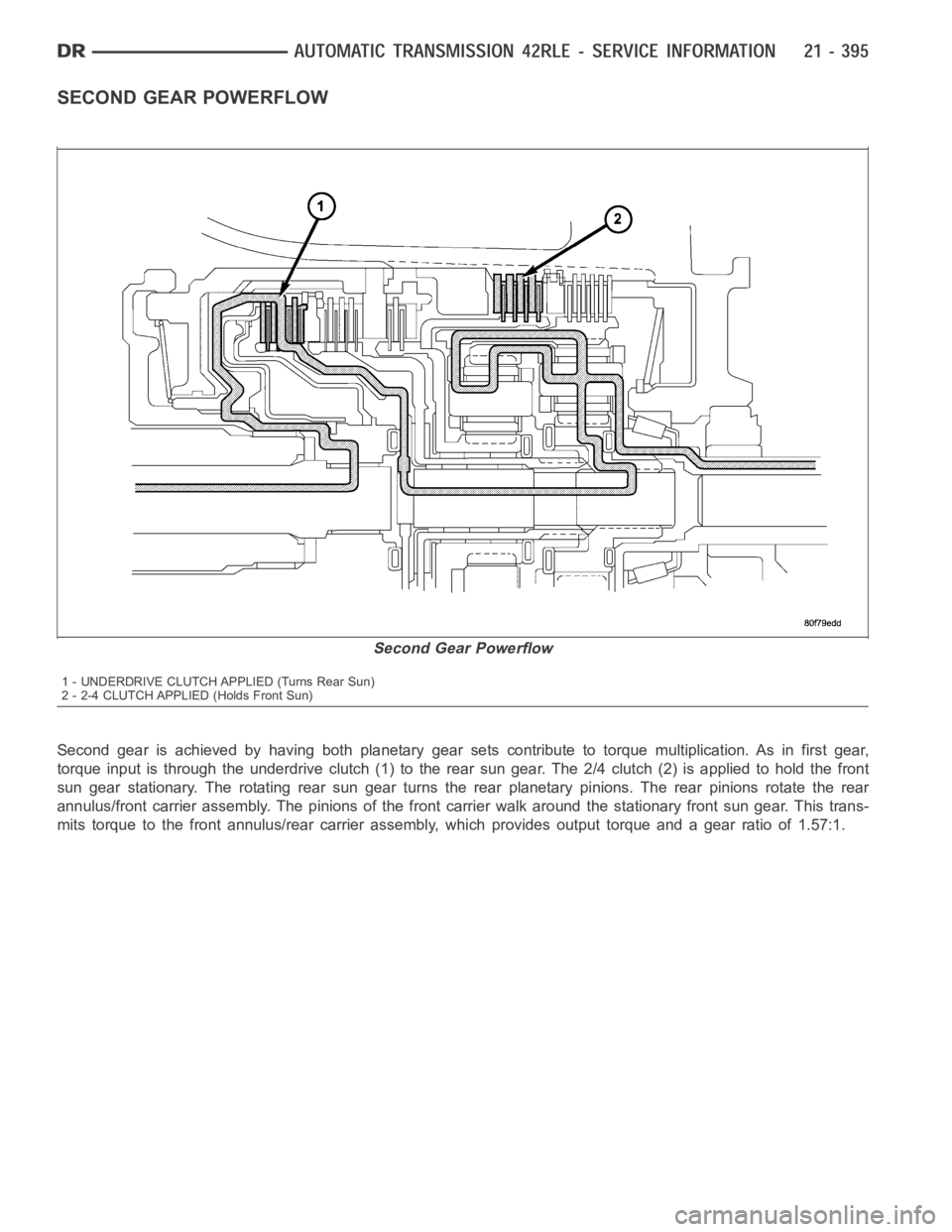
SECOND GEAR POWERFLOW
Second gear is achieved by having both planetary gear sets contribute to torque multiplication. As in first gear,
torque input is through the underdrive clutch (1) to the rear sun gear. The 2/4 clutch (2) is applied to hold the front
sun gear stationary. The rotating rear sun gear turns the rear planetary pinions. The rear pinions rotate the rear
annulus/front carrier assembly. The pinions of the front carrier walk around the stationary front sun gear. This trans-
mits torque to the front annulus/rear carrier assembly, which provides output torque and a gear ratio of 1.57:1.
Second Gear Powerflow
1 - UNDERDRIVE CLUTCH APPLIED (Turns Rear Sun)
2 - 2-4 CLUTCH APPLIED (Holds Front Sun)