Page 2927 of 5267

16. Remove the starter motor.
17. Remove the engine to transmission collar.
18. Rotate crankshaft in clockwise direction until con-
verter bolts are accessible. Then remove bolts
one at a time. Rotate crankshaft with socket
wrench on dampener bolt.
19. Disconnect the transmission vent hose from the
transmission.
20. Remove transfer case. (Refer to 21 - TRANSMIS-
SION/TRANSFER CASE - REMOVAL)
21. Support rear of engine with safety stand or jack.
22. Raise transmission slightly with service jack to
relieve load on crossmember and supports.
23. Remove bolts securing rear support and cushion
to transmission and crossmember.
24. Remove bolts attaching crossmember to frame
and remove crossmember.
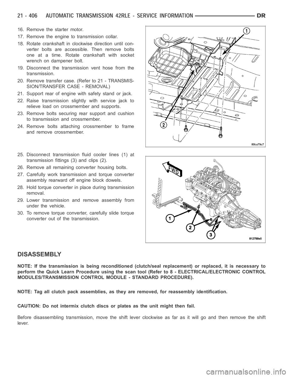
25. Disconnect transmission fluid cooler lines (1) at
transmission fittings (3) and clips (2).
26. Remove all remaining converter housing bolts.
27. Carefully work transmission and torque converter
assembly rearward off engine block dowels.
28. Hold torque converter in place during transmission
removal.
29. Lower transmission and remove assembly from
under the vehicle.
30. To remove torque converter, carefully slide torque
converter out of the transmission.
DISASSEMBLY
NOTE: If the transmission is being reconditioned (clutch/seal replacement) or replaced, it is necessary to
perform the Quick Learn Procedure using the scan tool (Refer to 8 - ELECTRICAL/ELECTRONIC CONTROL
MODULES/TRANSMISSION CONTROL MODULE - STANDARD PROCEDURE).
NOTE: Tag all clutch pack assemblies, as they are removed, for reassembly identification.
CAUTION: Do not intermix clutch discs or plates as the unit might then fail.
Before disassembling transmission, move the shift lever clockwise as faras it will go and then remove the shift
lever.
Page 2939 of 5267
32. Remove the input clutch assembly (1).
33. Removethe#4thrustplate(2).
34. Remove the front sun gear assembly (1) and #4
thrust washer (if still in place).
Page 2941 of 5267
NOTE: Verify that Compressor 5058A (1) is cen-
tered properly over the 2/4 clutch retainer (4)
before compressing. If necessary, fasten the
5058A bar to the bellhousing flange with any com-
bination of locking pliers and bolts to center the
tool properly.
37. Install and load Compressor 5058A to remove the
2/4 clutch retainer snap ring (3).
NOTE: The 2/4 Clutch Piston has bonded seals
which are not individually serviceable. Seal
replacement requires replacement of the piston
assembly.
38. Remove the 2/4 clutch retainer (1).
39. Remove the 2/4 clutch return spring (1).
Page 2942 of 5267
40. Remove the 2/4 clutch pack (1, 2).
41. Remove the tapered snap ring (4).
42. Remove the low/reverse reaction plate (1).
Page 2943 of 5267
43. Remove one (1) low/reverse clutch disc to facili-
tate snap ring removal.
44. Remove the low/reverse reaction plate snap ring
(2).
45. Remove the low/reverse clutch pack (1, 2).
Page 2948 of 5267
56. Remove the park sprag pivot retaining screw.
57. Drive out the anchor shaft using suitable punch
(1).
58. Remove the guide bracket pivot pin (1). Inspect
all components for wear and replace if necessary.
NOTE: The Low/Reverse Clutch Piston has bonded
seals which are not individually serviceable. Seal
replacement requires replacement of the piston
assembly.
59. Remove the low/reverse clutch piston (1).
60. Remove the low/reverse piston retainer screws.
Page 2949 of 5267
61. Remove low/reverse piston retainer (1).
62. Remove the low/reverse piston retainer gasket
(2).
ASSEMBLY
NOTE: If the transmission assembly is being reconditioned (clutch/seal replacement) or replaced, it is nec-
essary to perform the Quick Learn Procedure using the scan tool (Refer to 8 -ELECTRICAL/ELECTRONIC
CONTROL MODULES/TRANSMISSION CONTROL MODULE - STANDARD PROCEDURE).
1. Install the output bearing cups using Installer
5050A.
Page 2951 of 5267
NOTE: The Low/Reverse Clutch Piston has bonded
seals which are not individually serviceable. Seal
replacement requires replacement of the piston
assembly.
5. Install low/reverse clutch piston (1).
6. Assemble guide bracket (1) assembly as shown, if
necessary.
CAUTION: When installing, be sure guide bracket
and split sleeve touch the rear of the transmission
case.
7. Install guide bracket pivot pin (1).
8. Install park sprag pivot retaining bolt and torque to
4.5 Nꞏm (40 in. lbs.).