Page 2473 of 5267
SPECIFICATIONS
TORQUE
DESCRIPTION Nꞏm Ft. Lbs. In. Lbs.
Pitman Arm
Gear Shaft Nut300 225 —
Drag Link
Pitman Arm88 65 —
Drag Link
Tie Rod54
Then an additional 90°40
Then an additional 90°—
Drag Link
Adjuster Clamp61 45 —
Tie Rod End
Knuckle54
Then an additional 90°40
Then an additional 90°—
Tie Rod End
Adjuster Clamp61 45 —
Stabilizer Bar Link to Axle 68 50 —
Steering Damper
Axle95 70 —
Steering Damper
Tie Rod81 60 —
Page 2474 of 5267
SPECIAL TOOLS
STEERING LINKAGE
Remover Ball Stud MB-991113
Puller Tie Rod C-3894-A
Remover Ball Joint C-4150A
PITMAN ARM REMOVAL TOOL - 9615
Page 2475 of 5267
DAMPER
REMOVAL
1. Remove the steering damper mounting nuts and bolts.
2. Slide the damper from the isolation bushing.
3. Remove the damper.
INSTALLATION
1. Install the steering damper on the axle and isolation bushing. Tighten nut to 95 Nꞏm (75 ft. lbs.).
2. Install the steering damper on the tie rod. Tighten nut to 81 Nꞏm (60 ft. lbs.).
Page 2476 of 5267
DRAG LINK
REMOVAL
1. Remove the drag link nut (2) from the pitman arm
side (1).
2. Remove the drag link nut from the knuckle side.
3. Remove the drag link (2) from the right knuckle
and pitman arm (1) with Puller C-3894A (3).
INSTALLATION
1. Install the drag link (2) to the pitman arm (1). Install
the nut and tighten to 88 Nꞏm (65 ft. lbs.).
2. Install the drag link to the right steering knuckle.
Install the nut and tighten to 54 Nꞏm (40 ft. lbs.).
Then an additional 90°.
3. Install tie rod to the left steering knuckle and drag
link. Install the nuts and tighten to 54 Nꞏm (40 ft.
lbs.). Then an additional 90°.
4. Remove the supports and lower the vehicle to the
surface. Center steering wheel and adjust toe,
(Refer to 2 - SUSPENSION/WHEEL ALIGNMENT -
STANDARD PROCEDURE).
5. After adjustment tighten tie rod adjustment sleeve
clamp bolts to 61 Nꞏm (45 ft. lbs.).
NOTE:Positiontheclamponthesleevesoretain-
ing bolt is located on the bottom side of the sleeve.
Page 2478 of 5267
INSTALLATION
1. Align reference marks and install pitman arm.
2. Install the lock washer and retaining nut on the pit-
man shaft and tighten nut to 251 Nꞏm (185 ft. lbs.).
3. Install the drag link (1) to the pitman arm (5). Install
thenut(4)andtightento54Nꞏm(40ft.lbs.).Then
an additional 90°.
4. Remove the supports and lower the vehicle to the
surface. Center steering wheel and adjust toe,
(Refer to 2 - SUSPENSION/WHEEL ALIGNMENT -
STANDARD PROCEDURE).
5. After adjustment tighten tie rod adjustment sleeve
clamp bolts to 61 Nꞏm (45 ft. lbs.).
NOTE:Positiontheclamponthesleevesoretain-
ing bolt is located on the bottom side of the
sleeve.
Page 2479 of 5267
TIE ROD END
REMOVAL
1. Remove tie rod nuts (1).
2. Remove tie rod from drag link and left knuckle with
remover C-4150A.
INSTALLATION
1. Install tie rod (2) to the left steering knuckle and
drag link. Install the nuts (1) and tighten to 54 Nꞏm
(40 ft. lbs.) Then an additional 90°.
2. Remove the supports and lower the vehicle to the
surface. Center steering wheel and adjust toe,
(Refer to 2 - SUSPENSION/WHEEL ALIGNMENT -
STANDARD PROCEDURE).
3. After adjustment tighten tie rod adjustment sleeve
clamp bolts to 61 Nꞏm (45 ft. lbs.).
NOTE: Position the clamp on the sleeve so retaining bolt is located on the bottom side of the sleeve.
Page 2481 of 5267

page page
PUMP
DESCRIPTION ................................ 77
OPERATION .................................. 77
DIAGNOSIS AND TESTING
PUMP LEAKAGE ............................ 77
STANDARD PROCEDURE
FLUSHING POWER STEERING SYSTEM . . . . . 77
POWER STEERING PUMP - INITIAL
OPERATION................................ 78
REMOVAL
GAS ENGINE ............................... 79
DIESEL ENGINE............................ 79
INSTALLATION
GAS ENGINE ............................... 80
DIESEL ENGINE............................ 80
SPECIFICATIONS
TORQUE ................................... 81
FLUID
DESCRIPTION ................................ 82
STANDARD PROCEDURE
POWER STEERING FLUID LEVEL
CHECKING................................. 82
FLUID COOLER
REMOVAL .................................... 83
INSTALLATION ............................... 83
HOSES - I.F.S.
REMOVAL
RETURN HOSE - GEAR TO COOLER ......... 85PRESSURE HOSE .......................... 85
RETURN HOSE - RESERVOIR TO COOLER . . 85
INSTALLATION
RETURN HOSE - GEAR TO COOLER ......... 86
PRESSURE HOSE .......................... 86
RETURN HOSE - RESERVOIR TO COOLER . . 86
HOSES - LINK/COIL
REMOVAL
RETURN HOSE - GEAR TO COOLER ......... 87
PRESSURE HOSE .......................... 87
RETURN HOSE - RESERVOIR TO COOLER . . 87
INSTALLATION
RETURN HOSE - GEAR TO COOLER ......... 88
PRESSURE HOSE .......................... 88
RETURN HOSE - RESERVOIR TO COOLER . . 88
SWITCH-POWER STEERING PRESSURE
DESCRIPTION ................................ 89
OPERATION .................................. 89
REMOVAL - 5.7L - HD VEHICLES ONLY ......... 89
INSTALLATION - 5.7L - HD VEHICLES ONLY .... 89
PULLEY
REMOVAL .................................... 90
INSTALLATION ............................... 90
RESERVOIR
REMOVAL .................................... 91
INSTALLATION ............................... 91
Page 2482 of 5267

PUMP
DESCRIPTION
CAUTION: MOPARATF+4 is to be used in the power steering system. No other power steering or auto-
matic transmission fluid is to be used in the system. Damage may result to the power steering pump and
system if any other fluid is used, and do not overfill.
The pump is connected to the steering gear via the pressure hose and the return hose. The pump shaft has a
pressed-on pulley that is belt driven by the crankshaft pulley.
All vehicles are equipped with a power steering fluid cooler.
NOTE: Power steering pumps are not interchangeable with pumps installed on other vehicles.
OPERATION
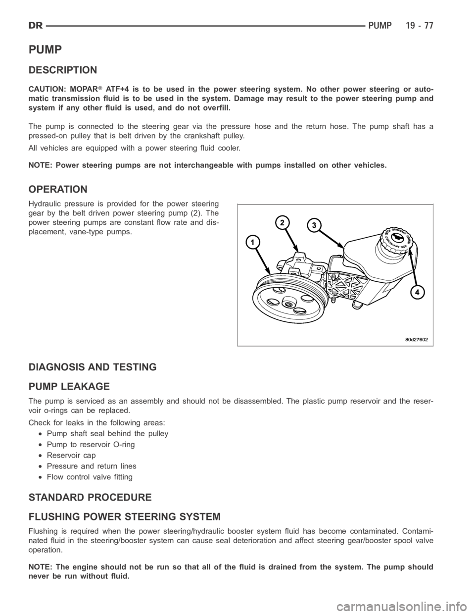
Hydraulic pressure is provided for the power steering
gear by the belt driven power steering pump (2). The
power steering pumps are constant flow rate and dis-
placement, vane-type pumps.
DIAGNOSIS AND TESTING
PUMP LEAKAGE
The pump is serviced as an assembly and should not be disassembled. The plastic pump reservoir and the reser-
voir o-rings can be replaced.
Check for leaks in the following areas:
Pump shaft seal behind the pulley
Pump to reservoir O-ring
Reservoir cap
Pressure and return lines
Flow control valve fitting
STANDARD PROCEDURE
FLUSHING POWER STEERING SYSTEM
Flushing is required when the power steering/hydraulic booster system fluid has become contaminated. Contami-
nated fluid in the steering/booster system can cause seal deterioration and affect steering gear/booster spool valve
operation.
NOTE: The engine should not be run so that all of the fluid is drained from thesystem. The pump should
never be run without fluid.