Page 2499 of 5267
FLOW AND PRESSURE TEST - AT POWER STEERING GEAR
NOTE: This test should only be done if necessary
after completing the Pump Flow And Pressure Test
1. Remove Analyzer from pump and pressure hose to
fan. Reattach pressure hose to pump.
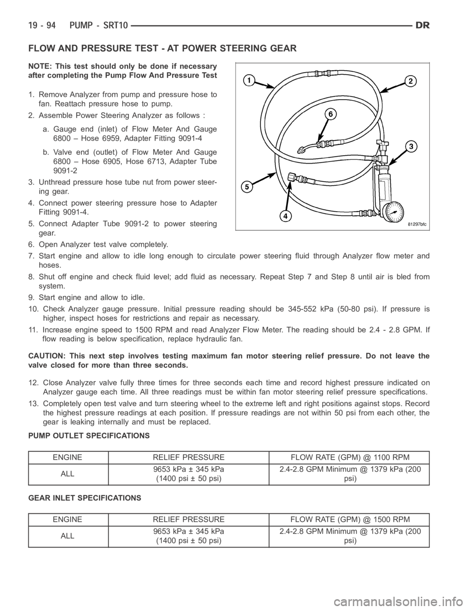
2. Assemble Power Steering Analyzer as follows :
a. Gauge end (inlet) of Flow Meter And Gauge
6800 – Hose 6959, Adapter Fitting 9091-4
b. Valve end (outlet) of Flow Meter And Gauge
6800 – Hose 6905, Hose 6713, Adapter Tube
9091-2
3. Unthread pressure hose tube nut from power steer-
ing gear.
4. Connect power steering pressure hose to Adapter
Fitting 9091-4.
5. Connect Adapter Tube 9091-2 to power steering
gear.
6. Open Analyzer test valve completely.
7. Start engine and allow to idle long enough to circulate power steering fluid through Analyzer flow meter and
hoses.
8. Shut off engine and check fluid level; add fluid as necessary. Repeat Step7andStep8untilairisbledfrom
system.
9. Start engine and allow to idle.
10. Check Analyzer gauge pressure. Initial pressure reading should be 345-552 kPa (50-80 psi). If pressure is
higher, inspect hoses for restrictions and repair as necessary.
11. Increase engine speed to 1500 RPM and read Analyzer Flow Meter. The reading should be 2.4 - 2.8 GPM. If
flow reading is below specification, replace hydraulic fan.
CAUTION: This next step involves testing maximum fan motor steering relief pressure. Do not leave the
valve closed for more than three seconds.
12. Close Analyzer valve fully three times for three seconds each time and record highest pressure indicated on
Analyzer gauge each time. All three readings must be within fan motor steering relief pressure specifications.
13. Completely open test valve and turn steering wheel to the extreme left and right positions against stops. Record
the highest pressure readings at each position. If pressure readings are not within 50 psi from each other, the
gear is leaking internally and must be replaced.
PUMP OUTLET SPECIFICATIONS
ENGINE RELIEF PRESSURE FLOW RATE (GPM) @ 1100 RPM
ALL9653 kPa ± 345 kPa
(1400 psi ± 50 psi)2.4-2.8 GPM Minimum @ 1379 kPa (200
psi)
GEAR INLET SPECIFICATIONS
ENGINE RELIEF PRESSURE FLOW RATE (GPM) @ 1500 RPM
ALL9653 kPa ± 345 kPa
(1400 psi ± 50 psi)2.4-2.8 GPM Minimum @ 1379 kPa (200
psi)
Page 2500 of 5267
STANDARD PROCEDURE
INITIAL OPERATION
WARNING: The fluid level should be checked with engine off to prevent injury from moving components.
NOTE: Remove as much of the old fluid out of the system as possible with a suction tool or by removing
a hose, when a component has failed. Then refill it with fresh fluid until itis clean. This may have to be
done more than once.
CAUTION: MOPAR
ATF+4 is to be used in the power steering system. No other power steering or auto-
matic transmission fluid is to be used in the system. Damage may result to the power steering pump and
system if any other fluid is used, and do not overfill.
Wipe filler cap clean, then check the fluid level. The dipstick should indicateCOLDwhen the fluid is at normal
ambient temperature.
1. Fill the pump fluid reservoir to the proper level and let the fluid settlefor at least two minutes.
2. Start the engine and let run for a few seconds then turn engine off.
3. Add fluid if necessary. Repeat the above procedure until the fluid levelremains constant after running the engine.
4. Raise the front wheels off the ground.
5. Slowly turn the steering wheel right and left, lightly contacting the wheel stops at least 20 times.
6. Check the fluid level add if necessary.
7. Lower the vehicle, start the engine, and use the DRB III to activate the hydraulic fan on full fan operation.
8. Turn the steering wheel slowly from lock to lock.
9. Stop the engine, check the fluid level and refill as required and repeat the process
CAUTION: Do not run a vehicle with foamy fluid for an extended period. This may cause pump damage.
10. If the fluid is extremely foamy or milky looking, allow the vehicle to stand a few minutes and repeat the pro-
cedure.
11. While the vehicle is in park, use the DRB III to activate the hydraulic fan to full fan operation and briefly rev the
engine up to 3000 rpm to fully engage the hydraulic fan.
12. Check the fluid level add if necessary.
Page 2502 of 5267
ASSEMBLY
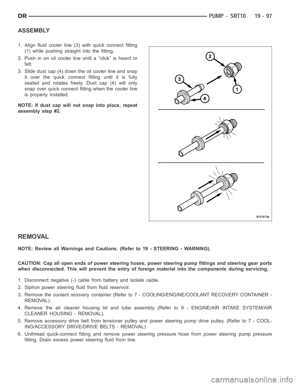
1. Align fluid cooler line (3) with quick connect fitting
(1) while pushing straight into the fitting.
2. Push in on oil cooler line until a “click” is heard or
felt.
3. Slide dust cap (4) down the oil cooler line and snap
it over the quick connect fitting until it is fully
seated and rotates freely. Dust cap (4) will only
snap over quick connect fitting when the cooler line
is properly installed.
NOTE: If dust cap will not snap into place, repeat
assembly step #2.
REMOVAL
NOTE: Review all Warnings and Cautions. (Refer to 19 - STEERING - WARNING).
CAUTION: Cap all open ends of power steering hoses, power steering pump fittings and steering gear ports
when disconnected. This will prevent the entry of foreign material into the components during servicing.
1. Disconnect negative (-) cable from battery and isolate cable.
2. Siphon power steering fluid from fluid reservoir.
3. Remove the coolant recovery container (Refer to 7 - COOLING/ENGINE/COOLANT RECOVERY CONTAINER -
REMOVAL).
4. Remove the air cleaner housing lid and tube assembly (Refer to 9 - ENGINE/AIR INTAKE SYSTEM/AIR
CLEANER HOUSING - REMOVAL).
5. Remove accessory drive belt from tensioner pulley and power steering pump drive pulley. (Refer to 7 - COOL-
ING/ACCESSORY DRIVE/DRIVE BELTS - REMOVAL)
6. Unthread quick-connect fitting and remove power steering pressure hose from power steering pump pressure
fitting. Drain excess power steering fluid from line.
Page 2503 of 5267
7. Disconnect A/C clutch coil wire connector (2).
8. Remove return hose from radiator fan at power steering pump reservoir.
9. Remove return hose from fluid cooler at power steering pump reservoir.
10. Remove three bolts mounting power steering
pump (5) to engine.
11. Remove power steering pump.
12. If required, transfer necessary parts from removed
power steering pump to replacement power steer-
ing pump. (Refer to 19 - STEERING/PUMP -
DISASSEMBLY).
Page 2504 of 5267
INSTALLATION
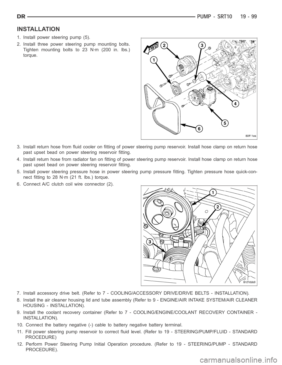
1. Install power steering pump (5).
2. Install three power steering pump mounting bolts.
Tighten mounting bolts to 23 Nꞏm (200 in. lbs.)
torque.
3. Install return hose from fluid cooler on fitting of power steering pump reservoir. Install hose clamp on return hose
past upset bead on power steering reservoir fitting.
4. Install return hose from radiator fan on fitting of power steering pump reservoir. Install hose clamp on return hose
past upset bead on power steering reservoir fitting.
5. Install power steering pressure hose in power steering pump pressure fitting. Tighten pressure hose quick-con-
nect fitting to 28 Nꞏm (21 ft. lbs.) torque.
6. Connect A/C clutch coil wire connector (2).
7. Install accessory drive belt. (Refer to 7 - COOLING/ACCESSORY DRIVE/DRIVE BELTS - INSTALLATION).
8. Install the air cleaner housing lid and tube assembly (Refer to 9 - ENGINE/AIR INTAKE SYSTEM/AIR CLEANER
HOUSING - INSTALLATION).
9. Install the coolant recovery container (Refer to 7 - COOLING/ENGINE/COOLANT RECOVERY CONTAINER -
INSTALLATION).
10. Connect the battery negative (-) cable to battery negative battery terminal.
11. Fill power steering pump reservoir to correct fluid level. (Refer to 19- STEERING/PUMP/FLUID - STANDARD
PROCEDURE)
12. Perform Power Steering Pump Initial Operation procedure. (Refer to 19- STEERING/PUMP - STANDARD
PROCEDURE).
Page 2505 of 5267
13. Check for leaks at all hose connections.
SPECIFICATIONS
TORQUE
DESCRIPTION Nꞏm Ft. Lbs. In. Lbs.
Power Steering Line nuts 28 21 —
Power Steering Pump
Mounting Bolts23 17 200
Page 2506 of 5267
SPECIAL TOOLS
POWER STEERING
ANALYZER SET, POWER STEERING FLOW/
PRESSURE 6815
ADAPTERS, POWER STEERING FLOW/PRESSURE
TESTER - 6893
HOSE, POWER STEERING-6959
Transmission Cooler Line Disconnect Tool - 8875
ADAPTERS, POWER STEERING 9091
Page 2507 of 5267
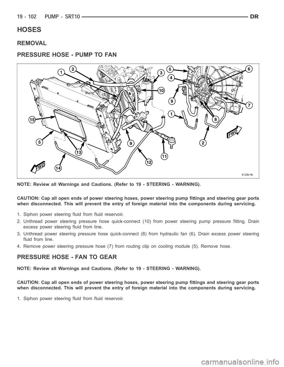
HOSES
REMOVAL
PRESSURE HOSE - PUMP TO FAN
NOTE: Review all Warnings and Cautions. (Refer to 19 - STEERING - WARNING).
CAUTION: Cap all open ends of power steering hoses, power steering pump fittings and steering gear ports
when disconnected. This will prevent the entry of foreign material into the components during servicing.
1. Siphon power steering fluid from fluid reservoir.
2. Unthread power steering pressure hose quick-connect (10) from power steering pump pressure fitting. Drain
excess power steering fluid from line.
3. Unthread power steering pressure hose quick-connect (8) from hydraulic fan (6). Drain excess power steering
fluid from line.
4. Remove power steering pressure hose (7) from routing clip on cooling module (5). Remove hose.
PRESSURE HOSE - FAN TO GEAR
NOTE: Review all Warnings and Cautions. (Refer to 19 - STEERING - WARNING).
CAUTION: Cap all open ends of power steering hoses, power steering pump fittings and steering gear ports
when disconnected. This will prevent the entry of foreign material into the components during servicing.
1. Siphon power steering fluid from fluid reservoir.