Page 2516 of 5267
FLUID COOLER TUBE
REMOVAL
1. Drain and siphon the power steering fluid.
2. Remove the underneath splash shield.
3. Disconnect the quick connect power steering fluid
cooler tubes (3) from the fluid cooler (1) using the
line disconnect tool 8875 (2).
4. Disconnect the quick connect (1) return and supply
tubes connected to the power steering fluid cooler
using the line disconnect tool 8875.
Page 2517 of 5267
5. Remove the tube retaining bracket (4) and then the
fluid cooler tubes (2).
INSTALLATION
1. Reconnect the quick connect fittings (2) to the
return and supply tubes (3) to the power steering
fluid cooler (1).
2. Reconnect the quick connect fittings (2) to the
return and supply tubes to the power steering fluid
hoses.
3. Install the tube retaining bracket (4).
4. Install the lower front air deflector.
5. Refill the power steering fluid (Refer to 19 -
STEERING/PUMP - STANDARD PROCEDURE).
Page 2518 of 5267
FLUID COOLER
REMOVAL
1. Drain and siphon the power steering fluid.
2. Remove the underneath splash shield.
3. Remove the two bolts (2) from the air deflector (4)
between the bumper (3) and A/C condensor (1).
4. Disconnect the return and supply hoses connected
to the power steering fluid cooler using the line dis-
connect tool 8875.
5. Disconnect the hose mounting bracket (3).
Page 2519 of 5267
6. Remove the mounting bracket bolts (1) securing
the fluid cooler (3) to the brace.
7. Remove the fluid cooler (1) from the vehicle.
NOTE: If needed disconnect the power steering
fluid cooler hoses (3) from the fluid cooler (1)
using special tool 8875 (2).
Page 2521 of 5267
3. Reconnect the quick connect fitting (1) to the return
and supply hoses to the power steering fluid cooler.
4. Install the hose retaining bracket (3).
5. Install the air deflector shield (4).
6. Install the lower front air deflector.
7. Refill the power steering fluid (Refer to 19 -
STEERING/PUMP - STANDARD PROCEDURE).
Page 3011 of 5267

ADJUSTMENT PROCEDURE
1. Remove the steering column trim as necessary for
access to the brake transmission shift interlock.
2. Shift the transmission into the PARK position.
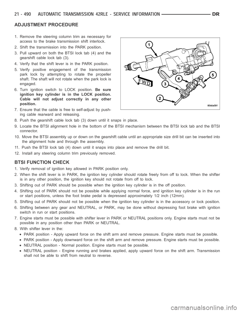
3. Pull upward on both the BTSI lock tab (4) and the
gearshift cable lock tab (3).
4. Verify that the shift lever is in the PARK position.
5. Verify positive engagement of the transmission
park lock by attempting to rotate the propeller
shaft. The shaft will not rotate when the park lock is
engaged.
6. Turn ignition switch to LOCK position.Be sure
ignition key cylinder is in the LOCK position.
Cable will not adjust correctly in any other
position.
7. Ensure that the cable is free to self-adjust by push-
ing cable rearward and releasing.
8. Push the gearshift cable lock tab (3) down until it snaps in place.
9. Locate the BTSI alignment hole in the bottom of the BTSI mechanism betweentheBTSIlocktabandtheBTSI
connector.
10. Move the BTSI assembly up or down on the gearshift cable until an appropriate size drill bit can be inserted into
the alignment hole and through the assembly.
11. Push the BTSI lock tab (4) down until it snaps into place and remove the drill bit.
12. Install any steering column trim previously removed.
BTSI FUNCTION CHECK
1. Verify removal of ignition key allowed in PARK position only.
2. When the shift lever is in PARK, the ignition key cylinder should rotate freely from off to lock. When the shifter
is in any other position, the ignition key should not rotate from off to lock.
3. Shifting out of PARK should be possible when the ignition key cylinder isin the off position.
4. Shifting out of PARK should not be possible while applying normal force,and ignition key cylinder is in the run
or start positions, unless the foot brake pedal is depressed approximately1/2inch(12mm).
5. Shifting out of PARK should not be possible when the ignition key cylinder is in the accessory or lock position.
6. Shifting between any gear and NEUTRAL, or PARK, may be done without depressing foot brake with ignition
switch in run or start positions.
7. Engine starts must be possible with shifter lever in PARK or NEUTRAL positions only. Engine starts must not be
possible in any position other than PARK or NEUTRAL.
8. With shifter lever in the:
PARK position - Apply upward force on the shift arm and remove pressure. Enginestartsmustbepossible.
PARK position - Apply downward force on the shift arm and remove pressure. Engine starts must be possible.
NEUTRAL position - Normal position. Engine starts must be possible.
NEUTRAL position - Engine running and brakes applied, apply upward force on the shift arm. Transmission
shall not be able to shift from neutral to reverse.
Page 3018 of 5267

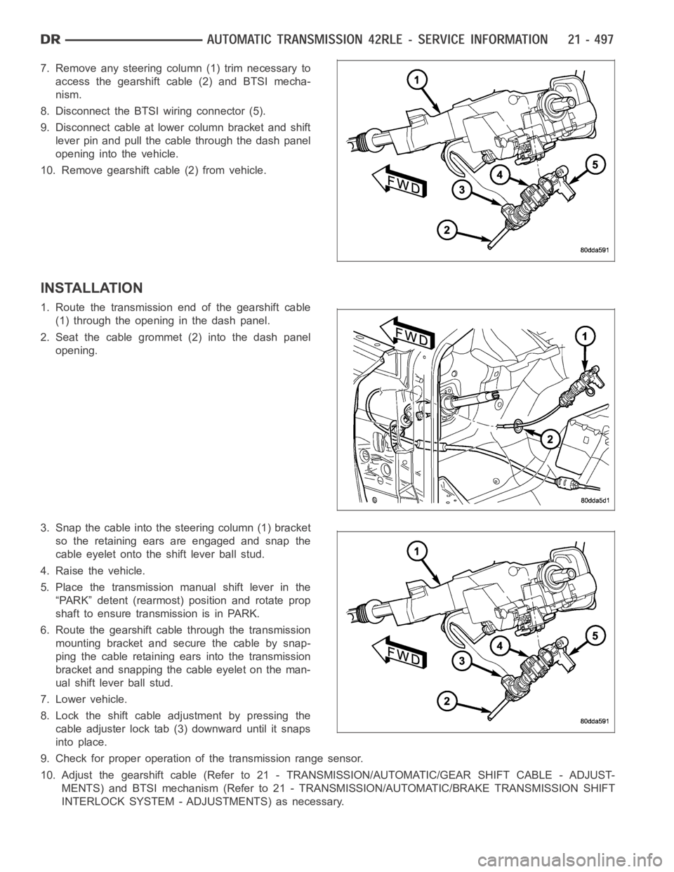
7. Remove any steering column (1) trim necessary to
access the gearshift cable (2) and BTSI mecha-
nism.
8. Disconnect the BTSI wiring connector (5).
9. Disconnect cable at lower column bracket and shift
lever pin and pull the cable through the dash panel
opening into the vehicle.
10. Remove gearshift cable (2) from vehicle.
INSTALLATION
1. Route the transmission end of the gearshift cable
(1) through the opening in the dash panel.
2. Seat the cable grommet (2) into the dash panel
opening.
3. Snap the cable into the steering column (1) bracket
so the retaining ears are engaged and snap the
cable eyelet onto the shift lever ball stud.
4. Raise the vehicle.
5. Place the transmission manual shift lever in the
“PARK” detent (rearmost) position and rotate prop
shaft to ensure transmission is in PARK.
6. Route the gearshift cable through the transmission
mounting bracket and secure the cable by snap-
ping the cable retaining ears into the transmission
bracket and snapping the cable eyelet on the man-
ual shift lever ball stud.
7. Lower vehicle.
8. Lock the shift cable adjustment by pressing the
cable adjuster lock tab (3) downward until it snaps
into place.
9. Check for proper operation of the transmission range sensor.
10. Adjust the gearshift cable (Refer to 21 - TRANSMISSION/AUTOMATIC/GEAR SHIFT CABLE - ADJUST-
MENTS) and BTSI mechanism (Refer to 21 - TRANSMISSION/AUTOMATIC/BRAKE TRANSMISSION SHIFT
INTERLOCK SYSTEM - ADJUSTMENTS) as necessary.
Page 3019 of 5267

ADJUSTMENTS - GEARSHIFT CABLE
Check adjustment by starting the engine in PARK and NEUTRAL. Adjustment isCORRECT if the engine starts only
in these positions. Adjustment is INCORRECT if the engine starts in one butnot both positions. If the engine starts
in any position other than PARK or NEUTRAL, or if the engine will not start atall, the transmission range sensor
may be faulty.
Gearshift Adjustment Procedure
1. Shift transmission into PARK.
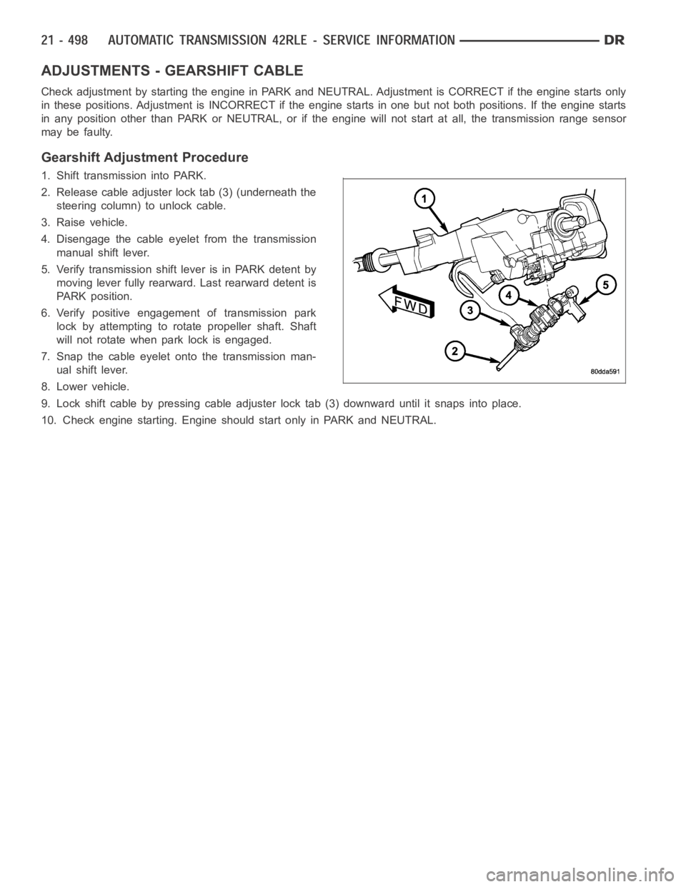
2. Release cable adjuster lock tab (3) (underneath the
steering column) to unlock cable.
3. Raise vehicle.
4. Disengage the cable eyelet from the transmission
manual shift lever.
5. Verify transmission shift lever is in PARK detent by
moving lever fully rearward. Last rearward detent is
PARK position.
6. Verify positive engagement of transmission park
lock by attempting to rotate propeller shaft. Shaft
will not rotate when park lock is engaged.
7. Snap the cable eyelet onto the transmission man-
ual shift lever.
8. Lower vehicle.
9. Lock shift cable by pressing cable adjuster lock tab (3) downward until it snaps into place.
10. Check engine starting. Engine should start only in PARK and NEUTRAL.