2006 DODGE RAM SRT-10 steering
[x] Cancel search: steeringPage 4511 of 5267
INSTALLATION
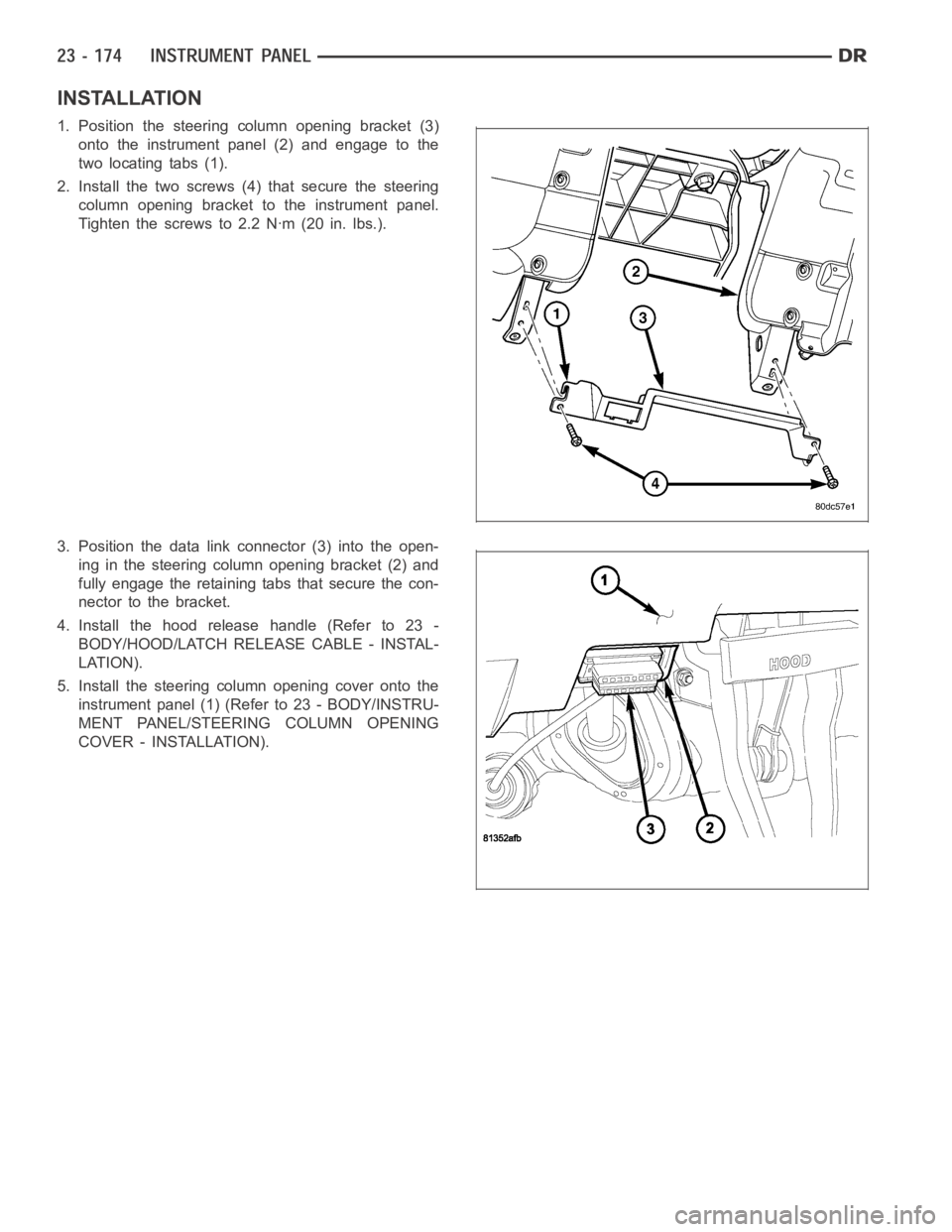
1. Position the steering column opening bracket (3)
onto the instrument panel (2) and engage to the
two locating tabs (1).
2. Install the two screws (4) that secure the steering
column opening bracket to the instrument panel.
Tighten the screws to 2.2 Nꞏm (20 in. lbs.).
3. Position the data link connector (3) into the open-
ing in the steering column opening bracket (2) and
fully engage the retaining tabs that secure the con-
nector to the bracket.
4. Install the hood release handle (Refer to 23 -
BODY/HOOD/LATCH RELEASE CABLE - INSTAL-
LATION).
5. Install the steering column opening cover onto the
instrument panel (1) (Refer to 23 - BODY/INSTRU-
MENT PANEL/STEERING COLUMN OPENING
COVER - INSTALLATION).
Page 4512 of 5267
STORAGE BIN
REMOVAL
WARNING: On vehicles equipped with airbags, disable the airbag system before attempting any steering
wheel, steering column, seat belt tensioner, or instrument panel component diagnosis or service. Discon-
nect and isolate the battery negative (ground) cable, then wait two minutes for the airbag system capacitor
to discharge before performing further diagnosis or service. This is the only sure way to disable the airbag
system. Failure to take the proper precautions could result in accidentalairbag deployment and possible
personal injury or death.
NOTE: A storage bin replaces the cup holder in
the instrument panel when the vehicle is equipped
with a floor console.
1. Remove the instrument panel center bezel (Refer
to 23 - BODY/INSTRUMENT PANEL/INSTRU-
MENT PANEL CENTER BEZEL - REMOVAL).
2. Removethefloorconsole(Referto23-BODY/IN-
TERIOR/FLOOR CONSOLE - REMOVAL).
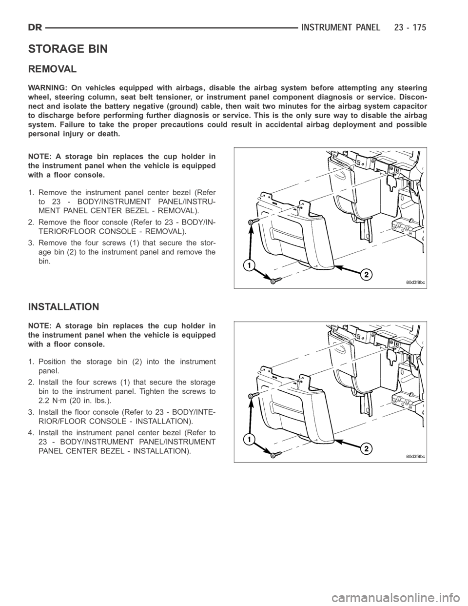
3. Remove the four screws (1) that secure the stor-
age bin (2) to the instrument panel and remove the
bin.
INSTALLATION
NOTE: A storage bin replaces the cup holder in
the instrument panel when the vehicle is equipped
with a floor console.
1. Position the storage bin (2) into the instrument
panel.
2. Install the four screws (1) that secure the storage
bin to the instrument panel. Tighten the screws to
2.2 Nꞏm (20 in. lbs.).
3. Install the floor console (Refer to 23 - BODY/INTE-
RIOR/FLOOR CONSOLE - INSTALLATION).
4. Install the instrument panel center bezel (Refer to
23 - BODY/INSTRUMENT PANEL/INSTRUMENT
PANEL CENTER BEZEL - INSTALLATION).
Page 4559 of 5267
SEATS
WARNING
WARNINGS - RESTRAINT SYSTEM
WARNING: To avoid personal injury or death, during and following any seat beltorchildrestraintanchor
service, carefully inspect all seat belts, buckles, mounting hardware, retractors, tether straps, and anchors
for proper installation, operation, or damage. Replace any belt that is cut, frayed, or torn. Straighten any
belt that is twisted. Tighten any loose fasteners. Replace any belt that has a damaged or ineffective buckle
or retractor. Replace any belt that has a bent or damaged latch plate or anchor plate. Replace any child
restraint anchor or the unit to which the anchor is integral that has been bent or damaged. Never attempt to
repair a seat belt or child restraint component. Always replace damaged orineffective seat belt and child
restraint components with the correct, new and unused replacement parts listed in the DaimlerChrysler
Mopar
Parts Catalog.
WARNING: To avoid personal injury or death, on vehicles equipped with airbags, disable the supplemental
restraint system before attempting any steering wheel, steering column,airbag, seat belt tensioner, impact
sensor, or instrument panel component diagnosis or service. Disconnect and isolate the battery negative
(ground) cable, then wait two minutes for the system capacitor to discharge before performing further diag-
nosis or service. This is the only sure way to disable the supplemental restraint system. Failure to take the
proper precautions could result in accidental airbag deployment.
WARNING: To avoid personal injury or death on vehicles equipped with airbags, before performing any
welding operations disconnect and isolate the battery negative (ground)cable and disconnect all wire har-
ness connectors from the Occupant Restraint Controller (ORC). Failure totake the proper precautions could
result in accidental airbag deployment and other possible damage to the supplemental restraint system cir-
cuits and components.
WARNING: To avoid personal injury or death, do not attempt to dismantle an airbag unit or tamper with its
inflator. Do not puncture, incinerate, or bring into contact with electricity. Do not store at temperatures
exceeding 93° C (200° F). An airbag inflator unit may contain sodium azide and potassium nitrate. These
materials are poisonous and extremely flammable. Contact with acid, water, or heavy metals may produce
harmful and irritating gases (sodium hydroxide is formed in the presence of moisture) or combustible com-
pounds. An airbag inflator unit may also contain a gas canister pressurizedtoover2500psi.
WARNING: To avoid personal injury or death, when handling a seat belt tensioner retractor, proper care
should be exercised to keep fingers out from under the retractor cover and away from the seat belt webbing
where it exits from the retractor cover.
WARNING: To avoid personal injury or death, replace all restraint system components only with parts spec-
ified in the DaimlerChrysler Mopar
Parts Catalog. Substitute parts may appear interchangeable, but internal
differences may result in inferior occupant protection.
WARNING: To avoid personal injury or death, the fasteners, screws, and bolts originally used for the
restraint system components must never be replaced with any substitutes.These fasteners have special
coatings and are specifically designed for the restraint system. Any timea new fastener is needed, replace
it with the correct fasteners provided in the service package or specifiedin the DaimlerChrysler Mopar
Parts Catalog.
WARNING: To avoid personal injury or death, when a steering column has an airbag unit attached, never
place the column on the floor or any other surface with the steering wheel orairbag unit face down.
Page 4732 of 5267
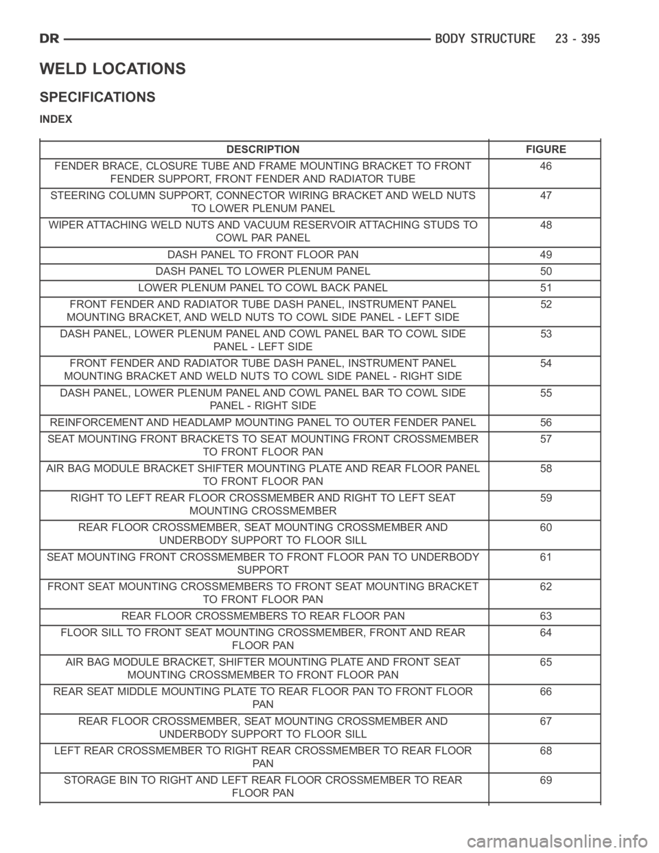
WELD LOCATIONS
SPECIFICATIONS
INDEX
DESCRIPTION FIGURE
FENDER BRACE, CLOSURE TUBE AND FRAME MOUNTING BRACKET TO FRONT
FENDER SUPPORT, FRONT FENDER AND RADIATOR TUBE46
STEERING COLUMN SUPPORT, CONNECTOR WIRING BRACKET AND WELD NUTS
TO LOWER PLENUM PANEL47
WIPER ATTACHING WELD NUTS AND VACUUM RESERVOIR ATTACHING STUDS TO
COWL PAR PANEL48
DASH PANEL TO FRONT FLOOR PAN 49
DASH PANEL TO LOWER PLENUM PANEL 50
LOWER PLENUM PANEL TO COWL BACK PANEL 51
FRONT FENDER AND RADIATOR TUBE DASH PANEL, INSTRUMENT PANEL
MOUNTING BRACKET, AND WELD NUTS TO COWL SIDE PANEL - LEFT SIDE52
DASH PANEL, LOWER PLENUM PANEL AND COWL PANEL BAR TO COWL SIDE
PA N E L - L E F T S I D E53
FRONT FENDER AND RADIATOR TUBE DASH PANEL, INSTRUMENT PANEL
MOUNTING BRACKET AND WELD NUTS TO COWL SIDE PANEL - RIGHT SIDE54
DASH PANEL, LOWER PLENUM PANEL AND COWL PANEL BAR TO COWL SIDE
PANEL - RIGHT SIDE55
REINFORCEMENT AND HEADLAMP MOUNTING PANEL TO OUTER FENDER PANEL 56
SEAT MOUNTING FRONT BRACKETS TO SEAT MOUNTING FRONT CROSSMEMBER
TO FRONT FLOOR PAN57
AIR BAG MODULE BRACKET SHIFTER MOUNTING PLATE AND REAR FLOOR PANEL
TO FRONT FLOOR PAN58
RIGHT TO LEFT REAR FLOOR CROSSMEMBER AND RIGHT TO LEFT SEAT
MOUNTING CROSSMEMBER59
REAR FLOOR CROSSMEMBER, SEAT MOUNTING CROSSMEMBER AND
UNDERBODY SUPPORT TO FLOOR SILL60
SEAT MOUNTING FRONT CROSSMEMBER TO FRONT FLOOR PAN TO UNDERBODY
SUPPORT61
FRONT SEAT MOUNTING CROSSMEMBERS TO FRONT SEAT MOUNTING BRACKET
TO FRONT FLOOR PAN62
REAR FLOOR CROSSMEMBERS TO REAR FLOOR PAN 63
FLOOR SILL TO FRONT SEAT MOUNTING CROSSMEMBER, FRONT AND REAR
FLOOR PAN64
AIR BAG MODULE BRACKET, SHIFTER MOUNTING PLATE AND FRONT SEAT
MOUNTING CROSSMEMBER TO FRONT FLOOR PAN65
REAR SEAT MIDDLE MOUNTING PLATE TO REAR FLOOR PAN TO FRONT FLOOR
PA N66
REAR FLOOR CROSSMEMBER, SEAT MOUNTING CROSSMEMBER AND
UNDERBODY SUPPORT TO FLOOR SILL67
LEFT REAR CROSSMEMBER TO RIGHT REAR CROSSMEMBER TO REAR FLOOR
PA N68
STORAGE BIN TO RIGHT AND LEFT REAR FLOOR CROSSMEMBER TO REAR
FLOOR PAN69
Page 4738 of 5267

Fig. 47 STEERING COLUMN SUPPORT
Page 5062 of 5267
The blend door actuators are diagnosed using a scan tool (Refer to 24 - HEATING & AIR CONDITIONING - DIAG-
NOSIS AND TESTING and to 24 - HVAC Electrical Diagnostics for more information).
The blend door actuators cannot be adjusted or repaired and, if faulty or damaged, they must be replaced.
REMOVAL
WARNING: On vehicles equipped with airbags, disable the airbag system before attempting any steering
wheel, steering column, or instrument panel component diagnosis or service. Disconnect and isolate the
battery negative (ground) cable, then wait two minutes for the airbag system capacitor to discharge before
performing further diagnosis or service. This is the only sure way to disable the airbag system. Failure to
take the proper precautions could result in accidental airbag deploymentand possible personal injury or
death.
NOTE: The single zone heating-A/C system is equipped with a single blend door actuator. The dual zone
system has two blend door actuators, one for the driver side blend-air doorand one for the passenger side
blend-air door.
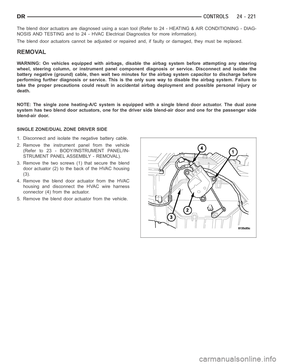
SINGLE ZONE/DUAL ZONE DRIVER SIDE
1. Disconnect and isolate the negative battery cable.
2. Remove the instrument panel from the vehicle
(Refer to 23 - BODY/INSTRUMENT PANEL/IN-
STRUMENT PANEL ASSEMBLY - REMOVAL).
3. Remove the two screws (1) that secure the blend
door actuator (2) to the back of the HVAC housing
(3).
4. Remove the blend door actuator from the HVAC
housing and disconnect the HVAC wire harness
connector (4) from the actuator.
5. Remove the blend door actuator from the vehicle.
Page 5067 of 5267
The mode door actuators cannot be adjusted or repaired and, if faulty or damaged, they must be replaced.
REMOVAL
WARNING: On vehicles equipped with airbags, disable the airbag system before attempting any steering
wheel, steering column, or instrument panel component diagnosis or service. Disconnect and isolate the
battery negative (ground) cable, then wait two minutes for the airbag system capacitor to discharge before
performing further diagnosis or service. This is the only sure way to disable the airbag system. Failure to
take the proper precautions could result in an accidental airbag deployment and possible personal injury or
death.
NOTE: The heating-A/C system is equipped with two mode door actuators, onefor the panel/floor-air door
and one for the defrost-air door.
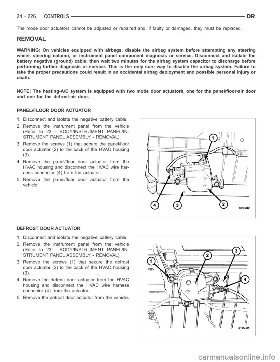
PANEL/FLOOR DOOR ACTUATOR
1. Disconnect and isolate the negative battery cable.
2. Remove the instrument panel from the vehicle
(Refer to 23 - BODY/INSTRUMENT PANEL/IN-
STRUMENT PANEL ASSEMBLY - REMOVAL).
3. Remove the screws (1) that secure the panel/floor
door actuator (2) to the back of the HVAC housing
(3).
4. Remove the panel/floor door actuator from the
HVAC housing and disconnect the HVAC wire har-
ness connector (4) from the actuator.
5. Remove the panel/floor door actuator from the
vehicle.
DEFROST DOOR ACTUATOR
1. Disconnect and isolate the negative battery cable.
2. Remove the instrument panel from the vehicle
(Refer to 23 - BODY/INSTRUMENT PANEL/IN-
STRUMENT PANEL ASSEMBLY - REMOVAL).
3. Remove the screws (1) that secure the defrost
door actuator (2) to the back of the HVAC housing
(3).
4. Remove the defrost door actuator from the HVAC
housing and disconnect the HVAC wire harness
connector (4) from the actuator.
5. Remove the defrost door actuator from the vehicle.
Page 5071 of 5267
REMOVAL
WARNING: On vehicles equipped with airbags, disable the airbag system before attempting any steering
wheel, steering column, or instrument panel component diagnosis or service. Disconnect and isolate the
battery negative (ground) cable, then wait two minutes for the airbag system capacitor to discharge before
performing further diagnosis or service. This is the only sure way to disable the airbag system. Failure to
take the proper precautions could result in accidental airbag deploymentand possible personal injury or
death.
1. Disconnect and isolate the negative battery cable.
2. Remove the glove box from the instrument panel
(Refer to 23 - BODY/INSTRUMENT PANEL/
GLOVE BOX - REMOVAL).
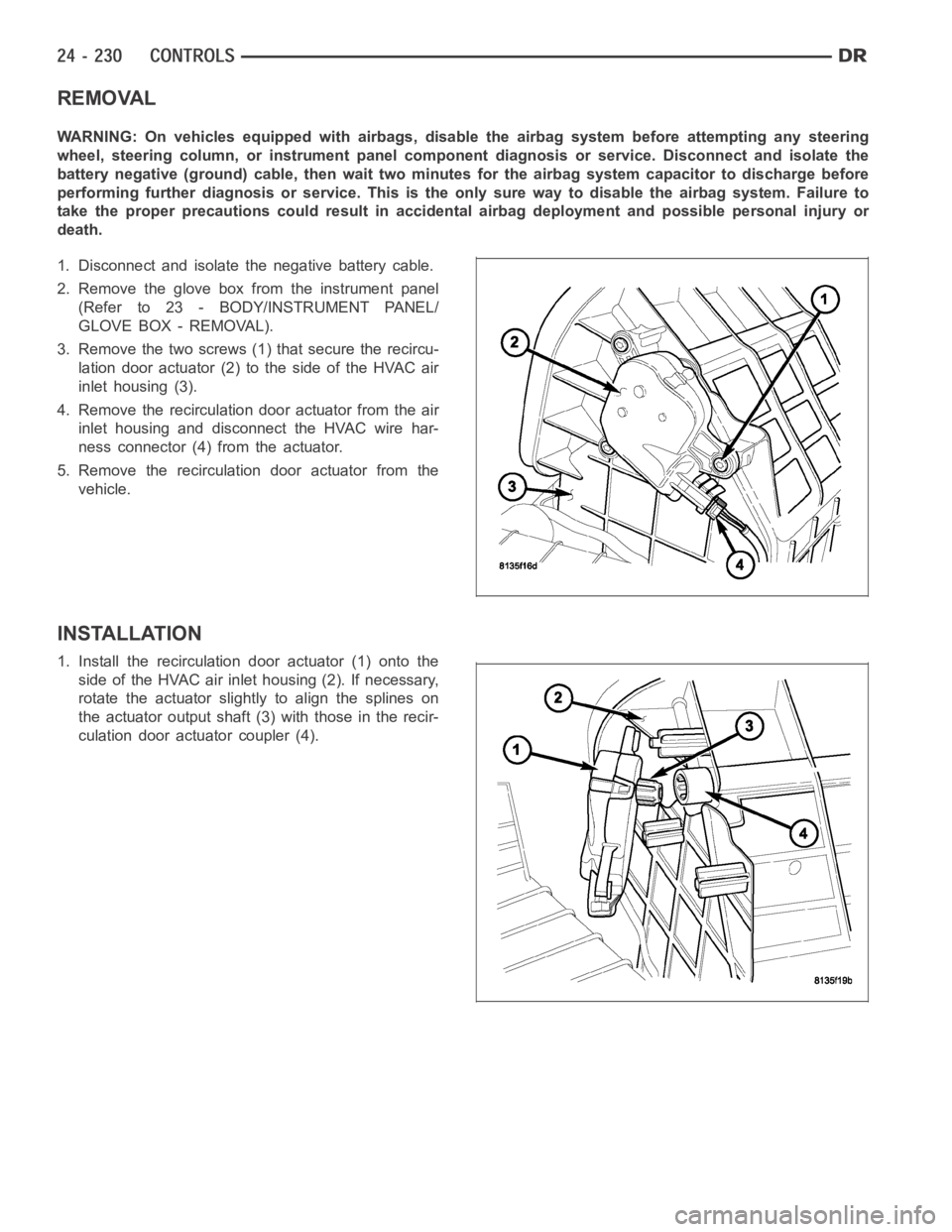
3. Remove the two screws (1) that secure the recircu-
lation door actuator (2) to the side of the HVAC air
inlet housing (3).
4. Remove the recirculation door actuator from the air
inlet housing and disconnect the HVAC wire har-
ness connector (4) from the actuator.
5. Remove the recirculation door actuator from the
vehicle.
INSTALLATION
1. Install the recirculation door actuator (1) onto the
side of the HVAC air inlet housing (2). If necessary,
rotate the actuator slightly to align the splines on
the actuator output shaft (3) with those in the recir-
culation door actuator coupler (4).