Page 4344 of 5267

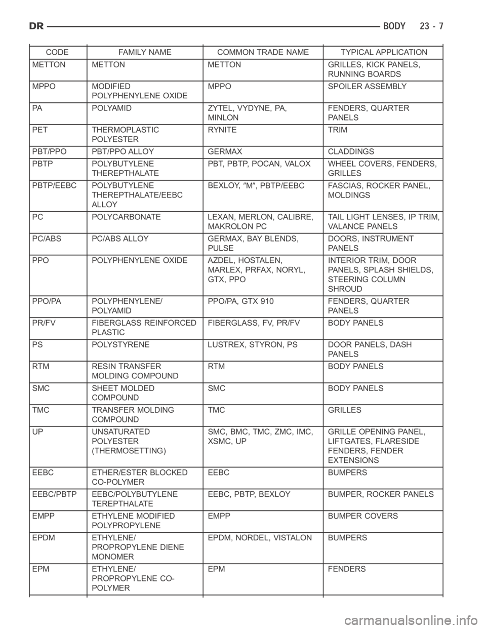
CODE FAMILY NAME COMMON TRADE NAME TYPICAL APPLICATION
METTON METTON METTON GRILLES, KICK PANELS,
RUNNING BOARDS
MPPO MODIFIED
POLYPHENYLENE OXIDEMPPO SPOILER ASSEMBLY
PA POLYAMID ZYTEL, VYDYNE, PA,
MINLONFENDERS, QUARTER
PA N E L S
PET THERMOPLASTIC
POLYESTERRYNITE TRIM
PBT/PPO PBT/PPO ALLOY GERMAX CLADDINGS
PBTP POLYBUTYLENE
THEREPTHALATEPBT, PBTP, POCAN, VALOX WHEEL COVERS, FENDERS,
GRILLES
PBTP/EEBC POLYBUTYLENE
THEREPTHALATE/EEBC
ALLOYBEXLOY,
M, PBTP/EEBC FASCIAS, ROCKER PANEL,
MOLDINGS
PC POLYCARBONATE LEXAN, MERLON, CALIBRE,
MAKROLON PCTAIL LIGHT LENSES, IP TRIM,
VA L A N C E PA N E L S
PC/ABS PC/ABS ALLOY GERMAX, BAY BLENDS,
PULSEDOORS, INSTRUMENT
PA N E L S
PPO POLYPHENYLENE OXIDE AZDEL, HOSTALEN,
MARLEX, PRFAX, NORYL,
GTX, PPOINTERIOR TRIM, DOOR
PANELS, SPLASH SHIELDS,
STEERING COLUMN
SHROUD
PPO/PA POLYPHENYLENE/
POLYAMIDPPO/PA, GTX 910 FENDERS, QUARTER
PA N E L S
PR/FV FIBERGLASS REINFORCED
PLASTICFIBERGLASS, FV, PR/FV BODY PANELS
PS POLYSTYRENE LUSTREX, STYRON, PS DOOR PANELS, DASH
PA N E L S
RTM RESIN TRANSFER
MOLDING COMPOUNDRTM BODY PANELS
SMC SHEET MOLDED
COMPOUNDSMC BODY PANELS
TMC TRANSFER MOLDING
COMPOUNDTMC GRILLES
UP UNSATURATED
POLYESTER
(THERMOSETTING)SMC, BMC, TMC, ZMC, IMC,
XSMC, UPGRILLE OPENING PANEL,
LIFTGATES, FLARESIDE
FENDERS, FENDER
EXTENSIONS
EEBC ETHER/ESTER BLOCKED
CO-POLYMEREEBC BUMPERS
EEBC/PBTP EEBC/POLYBUTYLENE
TEREPTHALATEEEBC, PBTP, BEXLOY BUMPER, ROCKER PANELS
EMPP ETHYLENE MODIFIED
POLYPROPYLENEEMPP BUMPER COVERS
EPDM ETHYLENE/
PROPROPYLENE DIENE
MONOMEREPDM, NORDEL, VISTALON BUMPERS
EPM ETHYLENE/
PROPROPYLENE CO-
POLYMEREPM FENDERS
Page 4345 of 5267

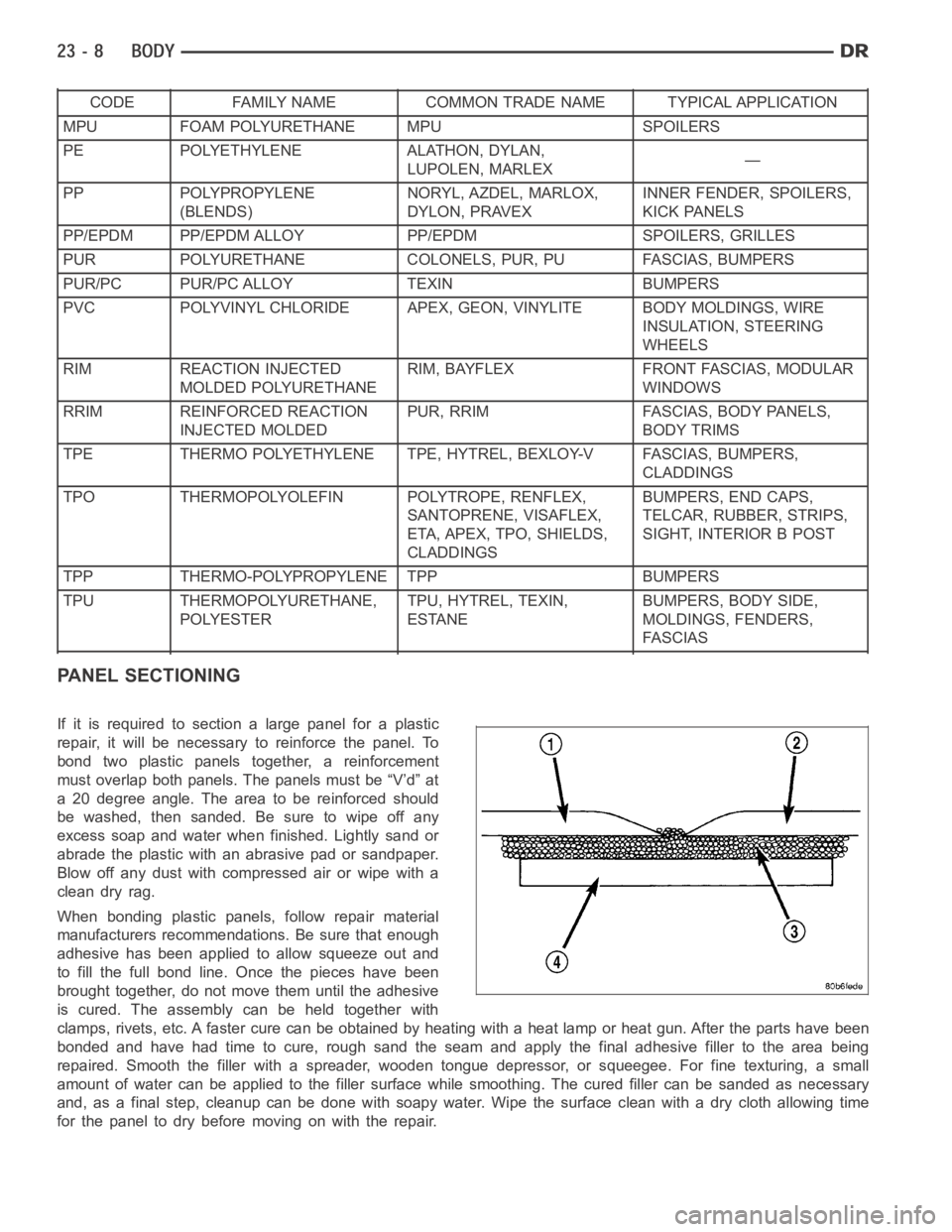
CODE FAMILY NAME COMMON TRADE NAME TYPICAL APPLICATION
MPU FOAM POLYURETHANE MPU SPOILERS
PE POLYETHYLENE ALATHON, DYLAN,
LUPOLEN, MARLEX—
PP POLYPROPYLENE
(BLENDS)NORYL, AZDEL, MARLOX,
DYLON, PRAVEXINNER FENDER, SPOILERS,
KICK PANELS
PP/EPDM PP/EPDM ALLOY PP/EPDM SPOILERS, GRILLES
PUR POLYURETHANE COLONELS, PUR, PU FASCIAS, BUMPERS
PUR/PC PUR/PC ALLOY TEXIN BUMPERS
PVC POLYVINYL CHLORIDE APEX, GEON, VINYLITE BODY MOLDINGS, WIRE
INSULATION, STEERING
WHEELS
RIM REACTION INJECTED
MOLDED POLYURETHANERIM, BAYFLEX FRONT FASCIAS, MODULAR
WINDOWS
RRIM REINFORCED REACTION
INJECTED MOLDEDPUR, RRIM FASCIAS, BODY PANELS,
BODY TRIMS
TPE THERMO POLYETHYLENE TPE, HYTREL, BEXLOY-V FASCIAS, BUMPERS,
CLADDINGS
TPO THERMOPOLYOLEFIN POLYTROPE, RENFLEX,
SANTOPRENE, VISAFLEX,
ETA, APEX, TPO, SHIELDS,
CLADDINGSBUMPERS, END CAPS,
TELCAR, RUBBER, STRIPS,
SIGHT, INTERIOR B POST
TPP THERMO-POLYPROPYLENE TPP BUMPERS
TPU THERMOPOLYURETHANE,
POLYESTERTPU, HYTREL, TEXIN,
ESTANEBUMPERS, BODY SIDE,
MOLDINGS, FENDERS,
FASCIAS
PANEL SECTIONING
If it is required to section a large panel for a plastic
repair, it will be necessary to reinforce the panel. To
bond two plastic panels together, a reinforcement
must overlap both panels. The panels must be “V’d” at
a 20 degree angle. The area to be reinforced should
be washed, then sanded. Be sure to wipe off any
excess soap and water when finished. Lightly sand or
abrade the plastic with an abrasive pad or sandpaper.
Blow off any dust with compressed air or wipe with a
clean dry rag.
When bonding plastic panels, follow repair material
manufacturers recommendations. Be sure that enough
adhesive has been applied to allow squeeze out and
to fill the full bond line. Once the pieces have been
brought together, do not move them until the adhesive
is cured. The assembly can be held together with
clamps, rivets, etc. A faster cure can be obtained by heating with a heat lamp or heat gun. After the parts have been
bonded and have had time to cure, rough sand the seam and apply the final adhesive filler to the area being
repaired. Smooth the filler with a spreader, wooden tongue depressor, or squeegee. For fine texturing, a small
amount of water can be applied to the filler surface while smoothing. The cured filler can be sanded as necessary
and, as a final step, cleanup can be done with soapy water. Wipe the surface clean with a dry cloth allowing time
for the panel to dry before moving on with the repair.
Page 4475 of 5267

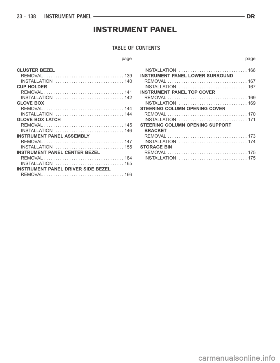
page page
CLUSTER BEZEL
REMOVAL ................................... 139
INSTALLATION .............................. 140
CUP HOLDER
REMOVAL ................................... 141
INSTALLATION .............................. 142
GLOVE BOX
REMOVAL ................................... 144
INSTALLATION .............................. 144
GLOVE BOX LATCH
REMOVAL ................................... 145
INSTALLATION .............................. 146
INSTRUMENT PANEL ASSEMBLY
REMOVAL ................................... 147
INSTALLATION .............................. 155
INSTRUMENT PANEL CENTER BEZEL
REMOVAL ................................... 164
INSTALLATION .............................. 165
INSTRUMENT PANEL DRIVER SIDE BEZEL
REMOVAL ................................... 166INSTALLATION .............................. 166
INSTRUMENT PANEL LOWER SURROUND
REMOVAL ................................... 167
INSTALLATION .............................. 167
INSTRUMENT PANEL TOP COVER
REMOVAL ................................... 169
INSTALLATION .............................. 169
STEERING COLUMN OPENING COVER
REMOVAL ................................... 170
INSTALLATION .............................. 171
STEERING COLUMN OPENING SUPPORT
BRACKET
REMOVAL ................................... 173
INSTALLATION .............................. 174
STORAGE BIN
REMOVAL ................................... 175
INSTALLATION .............................. 175
Page 4476 of 5267

CLUSTER BEZEL
REMOVAL
WARNING: On vehicles equipped with airbags, disable the airbag system before attempting any steering
wheel, steering column, seat belt tensioner, or instrument panel component diagnosis or service. Discon-
nect and isolate the battery negative (ground) cable, then wait two minutes for the airbag system capacitor
to discharge before performing further diagnosis or service. This is the only sure way to disable the airbag
system. Failure to take the proper precautions could result in accidentalairbag deployment and possible
personal injury or death.
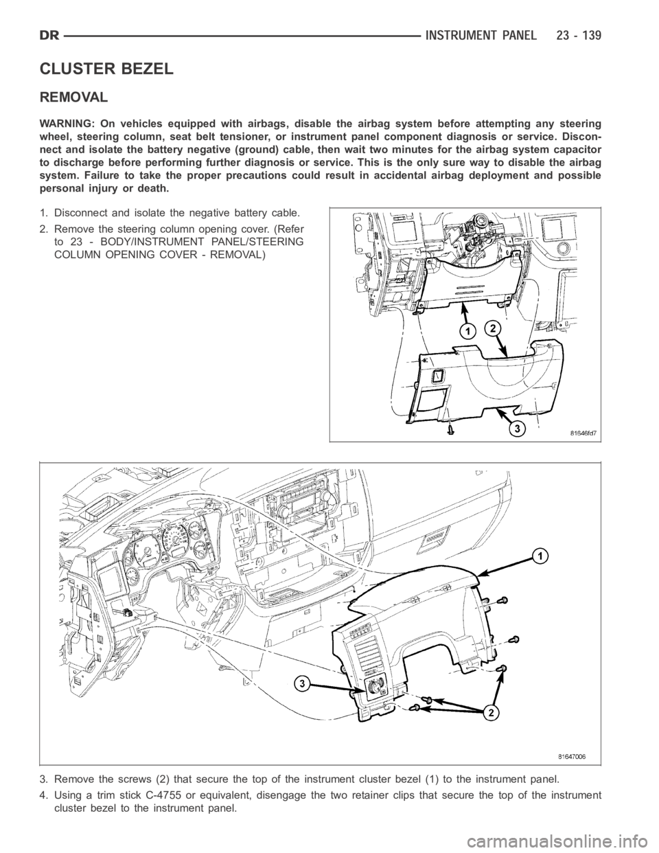
1. Disconnect and isolate the negative battery cable.
2. Remove the steering column opening cover. (Refer
to 23 - BODY/INSTRUMENT PANEL/STEERING
COLUMN OPENING COVER - REMOVAL)
3. Remove the screws (2) that secure the top of the instrument cluster bezel(1) to the instrument panel.
4. Using a trim stick C-4755 or equivalent, disengage the two retainer clips that secure the top of the instrument
cluster bezel to the instrument panel.
Page 4477 of 5267
5. Carefully disengage the instrument cluster bezel from the instrument panel opening and remove the bezel.
INSTALLATION
1. Install the instrument cluster bezel onto the instrument panel and fully engage the two retainer clips to the instru-
ment panel.
2. Install the screws (2) that secure the instrument cluster bezel to the instrument panel.
3. Install the steering column opening cover. (Refer to
23 - BODY/INSTRUMENT PANEL/STEERING
COLUMN OPENING COVER - INSTALLATION)
4. Connect the negative battery cable.
Page 4484 of 5267
INSTRUMENT PANEL ASSEMBLY
REMOVAL
WARNING: On vehicles equipped with airbags, disable the airbag system before attempting any steering
wheel, steering column, seat belt tensioner, or instrument panel component diagnosis or service. Discon-
nect and isolate the battery negative (ground) cable, then wait two minutes for the airbag system capacitor
to discharge before performing further diagnosis or service. This is the only sure way to disable the airbag
system. Failure to take the proper precautions could result in accidentalairbag deployment and possible
personal injury or death.
1. Disconnect and isolate the negative battery cable.
2. Remove the left a-pillar trim (Refer to 23 - BODY/
INTERIOR/A-PILLAR TRIM/GRAB HANDLE -
REMOVAL).
3. Disconnect the headliner wire harness connector
located at the a-pillar.
4. Remove the instrument panel top cover (Refer to
23 - BODY/INSTRUMENT PANEL/INSTRUMENT
PANEL TOP COVER - REMOVAL).
Page 4485 of 5267
5. Remove the left cowl trim panel (Refer to 23 -
BODY/INTERIOR/COWL TRIM - REMOVAL).
6.Removethesteeringcolumn(Referto19-
STEERING/COLUMN - REMOVAL).
Page 4486 of 5267
7. Remove the two bolts (1) that secure the steering
column support bracket to the instrument panel.
8. Remove the park brake release handle actuator
rod (Refer to 5 - BRAKES/PARKING BRAKE/RE-
LEASE - REMOVAL).