Page 2444 of 5267
GEAR - INDEPENDENT FRONT SUSPENSION
DESCRIPTION
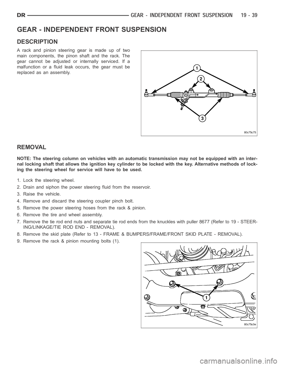
A rack and pinion steering gear is made up of two
main components, the pinon shaft and the rack. The
gear cannot be adjusted or internally serviced. If a
malfunction or a fluid leak occurs, the gear must be
replaced as an assembly.
REMOVAL
NOTE: The steering column on vehicles with an automatic transmission may not be equipped with an inter-
nal locking shaft that allows the ignition key cylinder to be locked with the key. Alternative methods of lock-
ing the steering wheel for service will have to be used.
1. Lock the steering wheel.
2. Drain and siphon the power steering fluid from the reservoir.
3. Raise the vehicle.
4. Remove and discard the steering coupler pinch bolt.
5. Remove the power steering hoses from the rack & pinion.
6. Remove the tire and wheel assembly.
7. Remove the tie rod end nuts and separate tie rod ends from the knuckles withpuller8677(Referto19-STEER-
ING/LINKAGE/TIE ROD END - REMOVAL).
8. Remove the skid plate (Refer to 13 - FRAME & BUMPERS/FRAME/FRONT SKID PLATE - REMOVAL).
9. Remove the rack & pinion mounting bolts (1).
Page 2445 of 5267
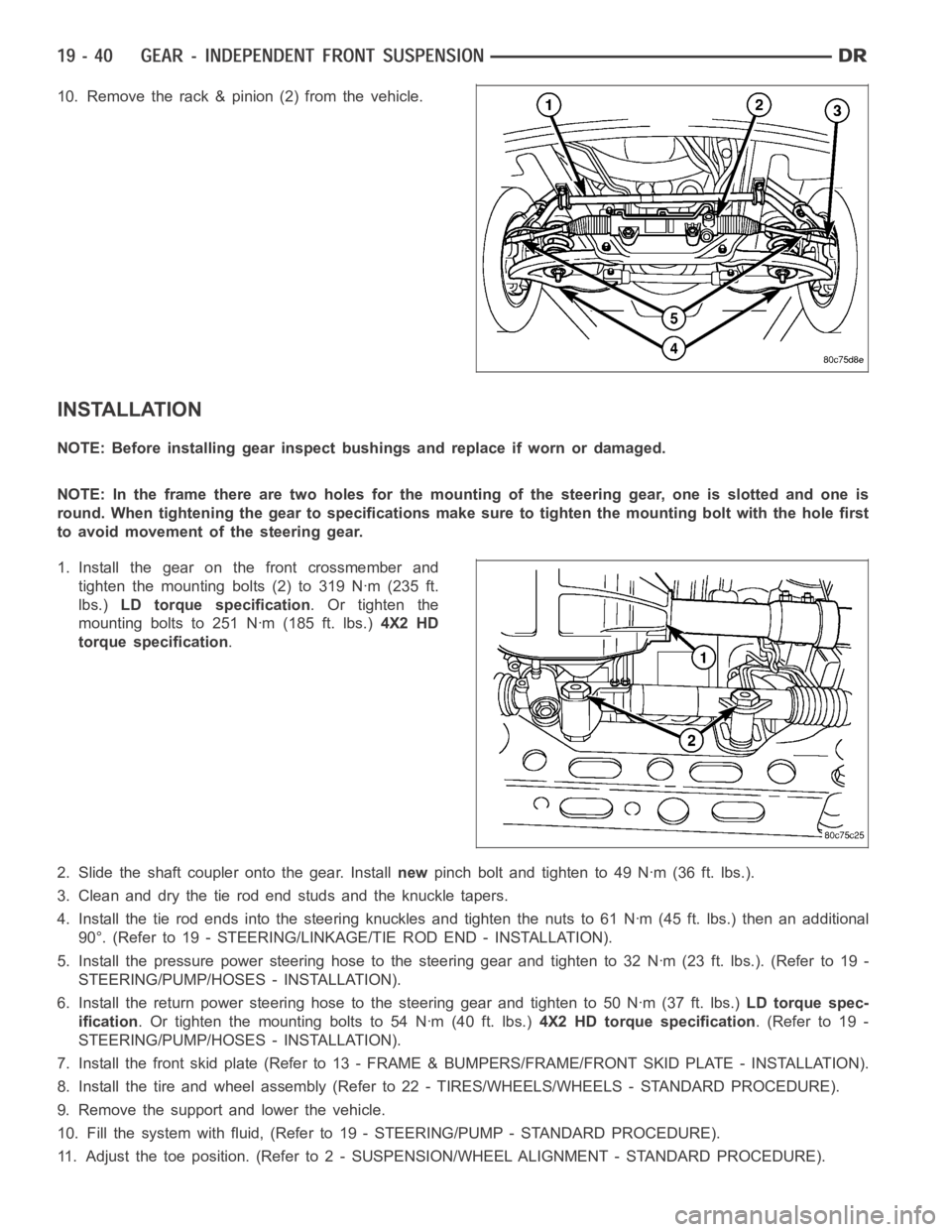
10. Remove the rack & pinion (2) from the vehicle.
INSTALLATION
NOTE: Before installing gear inspect bushings and replace if worn or damaged.
NOTE: In the frame there are two holes for the mounting of the steering gear,oneisslottedandoneis
round. When tightening the gear to specificationsmakesuretotightenthemounting bolt with the hole first
to avoid movement of the steering gear.
1. Install the gear on the front crossmember and
tighten the mounting bolts (2) to 319 Nꞏm (235 ft.
lbs.)LD torque specification.Ortightenthe
mounting bolts to 251 Nꞏm (185 ft. lbs.)4X2 HD
torque specification.
2. Slide the shaft coupler onto the gear. Installnewpinch bolt and tighten to 49 Nꞏm (36 ft. lbs.).
3. Clean and dry the tie rod end studs and the knuckle tapers.
4. Install the tie rod ends into the steering knuckles and tighten the nuts to61Nꞏm(45ft.lbs.)thenanadditional
90°. (Refer to 19 - STEERING/LINKAGE/TIE ROD END - INSTALLATION).
5. Install the pressure power steering hose to the steering gear and tightento32Nꞏm(23ft.lbs.).(Referto19-
STEERING/PUMP/HOSES - INSTALLATION).
6. Install the return power steering hose to the steering gear and tighten to50Nꞏm(37ft.lbs.)LD torque spec-
ification. Or tighten the mounting bolts to 54 Nꞏm (40 ft. lbs.)4X2 HD torque specification.(Referto19-
STEERING/PUMP/HOSES - INSTALLATION).
7. Install the front skid plate (Refer to 13 - FRAME & BUMPERS/FRAME/FRONT SKID PLATE - INSTALLATION).
8. Install the tire and wheel assembly (Refer to 22 - TIRES/WHEELS/WHEELS -STANDARD PROCEDURE).
9. Remove the support and lower the vehicle.
10. Fill the system with fluid, (Refer to 19 - STEERING/PUMP - STANDARD PROCEDURE).
11. Adjust the toe position. (Refer to 2 - SUSPENSION/WHEEL ALIGNMENT - STANDARD PROCEDURE).
Page 2446 of 5267
SPECIFICATIONS
TORQUE
DESCRIPTION Nꞏm Ft. Lbs. In. Lbs.
Rack and Pinion Steering
Gear
Gear to Frame Bolts
LD319 235 —
Rack and Pinion Steering
Gear
Gear to Frame Bolts
2WD HD251 185 —
Rack and Pinion Steering
Gear
Coupler Bolt49 36 —
Tie Rod End
Knuckle Nut61
Then tighten an additional
90°45
Then tighten an additional
90°—
Tie Rod End
Jam Nut127 94 —
Power Steering Line
Pressure Line32 23 —
Power Steering Line
Pressure Line To Pump37 27 —
Power Steering Line
Return Line
LD50 37 —
Power Steering Line
Return Line
HD54 40 —
Page 2447 of 5267
BUSHING
REMOVAL
1. Remove the steering gear (Refer to 19 - STEERING/GEAR - REMOVAL).
CAUTION: Do not overtighten the vise on the gear case.
2. Mount the steering gear in a soft jawed vise.
NOTE: If the bushings are seized a brass punch can be used to remove the bushings from the gear using
care not to strike the gear.
3. Remove the front mounting bushings.
4. Remove the rear mounting bushings.
5. Remove the steering gear from the vise and place it on the bench.
INSTALLATION
NOTE: Coat all bushings with a thin rubber lubricate oil prior to installation.
NOTE: A rubber mallet can be used to assist in the installation of the bushings once lubricated.
1. Coat the rear bushings with a thin rubber lubricate oil then install the rear bushings using a rubber mallet to seat
the bushings in the gear.
2. Coat the front bushings with a thin rubber lubricate oil then install thefront bushings using a rubber mallet to seat
the bushings in the gear.
3. Install the steering gear (Refer to 19 - STEERING/GEAR - INSTALLATION).
4. Adjust the toe position (if necessary) (Refer to 2 - SUSPENSION/WHEEL ALIGNMENT - STANDARD PROCE-
DURE).
Page 2448 of 5267
page page
GEAR - LINK/COIL
DESCRIPTION ................................ 44
OPERATION .................................. 44
REMOVAL .................................... 44
INSTALLATION ............................... 46
ADJUSTMENTS
ADJUSTMENT .............................. 47
SPECIFICATIONS
POWER STEERING GEAR ................... 47
TORQUE ................................... 48
SPECIAL TOOLS
POWER STEERING GEAR ................... 49
PITMAN SHAFT SEAL
REMOVAL
GAS ....................................... 51DIESEL .................................... 51
INSTALLATION
GAS ....................................... 52
DIESEL .................................... 53
STEERING GEAR INPUT SHAFT SEAL
REMOVAL .................................... 54
INSTALLATION ............................... 57
PITMAN SHAFT
REMOVAL
GAS ....................................... 59
DIESEL .................................... 59
INSTALLATION
GAS ....................................... 60
DIESEL .................................... 61
Page 2449 of 5267
GEAR - LINK/COIL
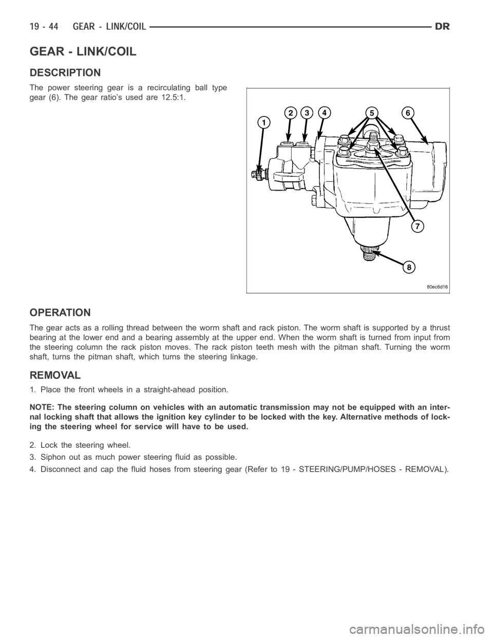
DESCRIPTION
The power steering gear is a recirculating ball type
gear (6). The gear ratio’s used are 12.5:1.
OPERATION
The gear acts as a rolling thread between the worm shaft and rack piston. Theworm shaft is supported by a thrust
bearing at the lower end and a bearing assembly at the upper end. When the worm shaft is turned from input from
the steering column the rack piston moves. The rack piston teeth mesh with the pitman shaft. Turning the worm
shaft, turns the pitman shaft, which turns the steering linkage.
REMOVAL
1. Place the front wheels in a straight-ahead position.
NOTE: The steering column on vehicles with an automatic transmission may not be equipped with an inter-
nal locking shaft that allows the ignition key cylinder to be locked with the key. Alternative methods of lock-
ing the steering wheel for service will have to be used.
2. Lock the steering wheel.
3. Siphon out as much power steering fluid as possible.
4. Disconnect and cap the fluid hoses from steering gear (Refer to 19 - STEERING/PUMP/HOSES - REMOVAL).
Page 2450 of 5267
5. Remove coupler pinch bolt (1) at the steering gear
and slide shaft off gear (2).
6.Markthepitmanshaftandpitmanarm(4)for
installation reference. Remove the pitman arm from
the shaft with pitman arm remover 9615 (2) (Refer
to 19 - STEERING/LINKAGE/PITMAN ARM -
REMOVAL).
7. Remove steering gear (1) three mounting bolts (2).
Remove the steering gear (1) from the vehicle.
Page 2451 of 5267
INSTALLATION
1. Position the steering gear (1) the frame rail and
install the three mounting bolts (2). Tighten the
mounting bolts to 196 Nꞏm (145 ft. lbs.).
2. Align steering coupler (1) on gear shaft (2). Install
pinch bolt and tighten to 49 Nꞏm (36 ft. lbs.) torque.
3. Align and install the pitman arm (5) (Refer to 19 -
STEERING/LINKAGE/PITMAN ARM - INSTALLA-
TION).
4. Install the washer and retaining nut (4) on the pit-
man shaft. Tighten the nut to 305 Nꞏm (225 ft. lbs.).
5. Connect fluid hoses to steering gear (Refer to 19 - STEERING/PUMP/HOSES- INSTALLATION), tighten to 32
Nꞏm (23 ft. lbs.).
6. Add fluid, (Refer to 19 - STEERING/PUMP - STANDARD PROCEDURE).
7. Reset the toe and center the steering wheel (Refer to 2 - SUSPENSION/WHEELALIGNMENT - STANDARD
PROCEDURE).