Page 2434 of 5267
7. Remove the blocker pin (1) from the inhibit link slot
(2) and remove the lever (3) by pulling forward
toward the steering wheel and to the left then
down.
INSTALLATION
1. Install the lever assembly (3) reversing the way it
came out using care to install the pin (2) in the
blocker to slider slot (1).
Page 2436 of 5267
10. Install the column back into place and tighten.
11. Install the kneeblocker (2) and steering column
reinforcement cover (1). (Refer to 23 - BODY/IN-
STRUMENT PANEL/KNEE BLOCKER -
INSTALLATION).
Page 2437 of 5267
UPPER STEERING COUPLING
REMOVAL
1. Disconnect the negative battery cable.
NOTE: The steering column on vehicles with an automatic transmission may not be equipped with an inter-
nal locking shaft that allows the ignition key cylinder to be locked with the key. Alternative methods of lock-
ing the steering wheel for service will have to be used.
2. Lock the steering wheel with the tire in the straight position.
3. Remove and discard the lower pinch bolt.
4. Lower the steering coupler shaft from the column.
5. Remove the upper steering coupling shaft (2) seal
by pushing in the four tags (1) securing it to the
panel.
6. Remove and discard the lower coupler pinch bolt
(1) from the lower steering coupling shaft (1).
7. Remove the upper steering coupling shaft (3) from
the vehicle.
Page 2438 of 5267
INSTALLATION
1. Install the upper steering coupling shaft (3) to the
vehicle.
2. Install the upper steering coupling shaft seal (2) by
pushing it in securing the four tangs (1) to the
panel.
NOTE: A new steering coupling shaft pinch bolt
for the upper and lower shafts must be used.
3. Install the steering coupler shaft (1) to the column.
4. Install the upper pinch bolt (3) use new bolt and
tighten to 57 N.m (42 ft.lbs).
5. Install the shaft to the lower coupler (1).
6. Install the lower pinch bolt (1) use new bolt and
tighten to 57 N.m (42 ft.lbs).
7. Unlock the steering wheel.
8. Reconnect the negative battery cable.
Page 2439 of 5267

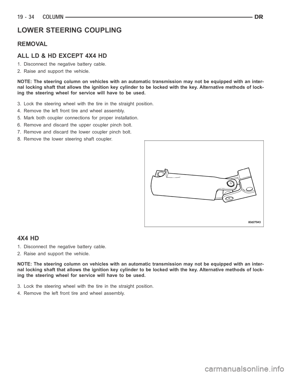
LOWER STEERING COUPLING
REMOVAL
ALLLD&HDEXCEPT4X4HD
1. Disconnect the negative battery cable.
2. Raise and support the vehicle.
NOTE: The steering column on vehicles with an automatic transmission may not be equipped with an inter-
nal locking shaft that allows the ignition key cylinder to be locked with the key. Alternative methods of lock-
ing the steering wheel for service will have to be used.
3. Lock the steering wheel with the tire in the straight position.
4. Remove the left front tire and wheel assembly.
5. Mark both coupler connections for proper installation.
6. Remove and discard the upper coupler pinch bolt.
7. Remove and discard the lower coupler pinch bolt.
8. Remove the lower steering shaft coupler.
4X4 HD
1. Disconnect the negative battery cable.
2. Raise and support the vehicle.
NOTE: The steering column on vehicles with an automatic transmission may not be equipped with an inter-
nal locking shaft that allows the ignition key cylinder to be locked with the key. Alternative methods of lock-
ing the steering wheel for service will have to be used.
3. Lock the steering wheel with the tire in the straight position.
4. Remove the left front tire and wheel assembly.
Page 2440 of 5267
5. Remove and discard the upper coupler pinch bolt
(1).
6. Remove and discard the lower coupler pinch bolt
(2).
7. Remove the lower steering shaft coupler (3).
Page 2441 of 5267
INSTALLATION
ALLLD&HDEXCEPT4X4HD
1. Install the coupler to the steering rack & pinion
using the marks made in the removal process.
2. Install the coupler to the intermediate shaft using
the marks made in the removal process.
NOTE: New pinch bolts must be used for reinstal-
lation.
3. Install the lower pinch bolt and tighten to 57 Nꞏm
(42 ft. lbs.).SRT10. Tighten to 38 Nꞏm (28 ft.
lbs.).
4. Install the upper pinch bolt and tighten to 57 Nꞏm
(42 ft. lbs.).
5. Install the left front tire and wheel assembly (Refer to 22 - TIRES/WHEELS/WHEELS - STANDARD PROCE-
DURE).
6. Lower the vehicle.
7. Reconnect the negative battery cable.
8. Unlock the steering wheel.
4X4 HD
1. Install the coupler (2) to the steering gear (3).
Page 2442 of 5267
2. Install the coupler (3) to the intermediate shaft (2).
NOTE: New pinch bolts must be used for reinstal-
lation.
3. Install the lower pinch bolt (3) and tighten to 28
Nꞏm (250 in. lbs.).
4. Install the upper pinch bolt (1) and tighten to 57
Nꞏm (42 ft. lbs.).
5. Install the left front tire and wheel assembly (Refer to 22 - TIRES/WHEELS/WHEELS - STANDARD PROCE-
DURE).
6. Lower the vehicle.
7. Reconnect the negative battery cable.
8. Unlock the steering wheel.