Page 2082 of 5267
33. Raise and support the vehicle.
34. Connect the hydraulic lines to the fan assembly and steering rack then connect the A/C hose to the fan shroud.
35. Install aNewoil filter.
36. Lower the vehicle.
37. Install upper radiator hose and connect the ground wire at the thermostat housing.
38. Install air cleaner housing cover assembly, connect throttle body airinlet duct, IAT sensor and CCV hose. (Refer
to 9 - ENGINE/AIR INTAKE SYSTEM - INSTALLATION).
39. Fill and purge air from the power steering system.
40. Fill engine crankcase with proper oil to correct level.
41. Fill and purge air from the cooling system (Refer to 7 - COOLING/ENGINE -STANDARD PROCEDURE - FILL-
ING COOLING SYSTEM).
42. Connect negative battery cable.
43. Start the vehicle and inspect for leaks.
44. Install the lower engine shield.
Page 2108 of 5267
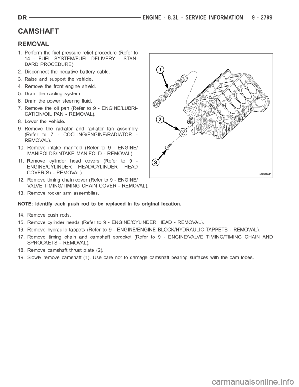
CAMSHAFT
REMOVAL
1. Perform the fuel pressure relief procedure (Refer to
14 - FUEL SYSTEM/FUEL DELIVERY - STAN-
DARD PROCEDURE).
2. Disconnect the negative battery cable.
3. Raise and support the vehicle.
4. Remove the front engine shield.
5. Drain the cooling system
6. Drain the power steering fluid.
7. Remove the oil pan (Refer to 9 - ENGINE/LUBRI-
CATION/OIL PAN - REMOVAL).
8. Lower the vehicle.
9. Remove the radiator and radiator fan assembly
(Refer to 7 - COOLING/ENGINE/RADIATOR -
REMOVAL).
10. Remove intake manifold (Refer to 9 - ENGINE/
MANIFOLDS/INTAKE MANIFOLD - REMOVAL).
11. Remove cylinder head covers (Refer to 9 -
ENGINE/CYLINDER HEAD/CYLINDER HEAD
COVER(S) - REMOVAL).
12. Remove timing chain cover (Refer to 9 - ENGINE/
VALVE TIMING/TIMING CHAIN COVER - REMOVAL).
13. Remove rocker arm assemblies.
NOTE: Identify each push rod to be replaced in its original location.
14. Remove push rods.
15. Remove cylinder heads (Refer to 9 - ENGINE/CYLINDER HEAD - REMOVAL).
16. Remove hydraulic tappets (Refer to 9 - ENGINE/ENGINE BLOCK/HYDRAULICTAPPETS - REMOVAL).
17. Remove timing chain and camshaft sprocket (Refer to 9 - ENGINE/VALVE TIMING/TIMING CHAIN AND
SPROCKETS - REMOVAL).
18. Remove camshaft thrust plate (2).
19. Slowly remove camshaft (1). Use care not to damage camshaft bearing surfaces with the cam lobes.
Page 2109 of 5267
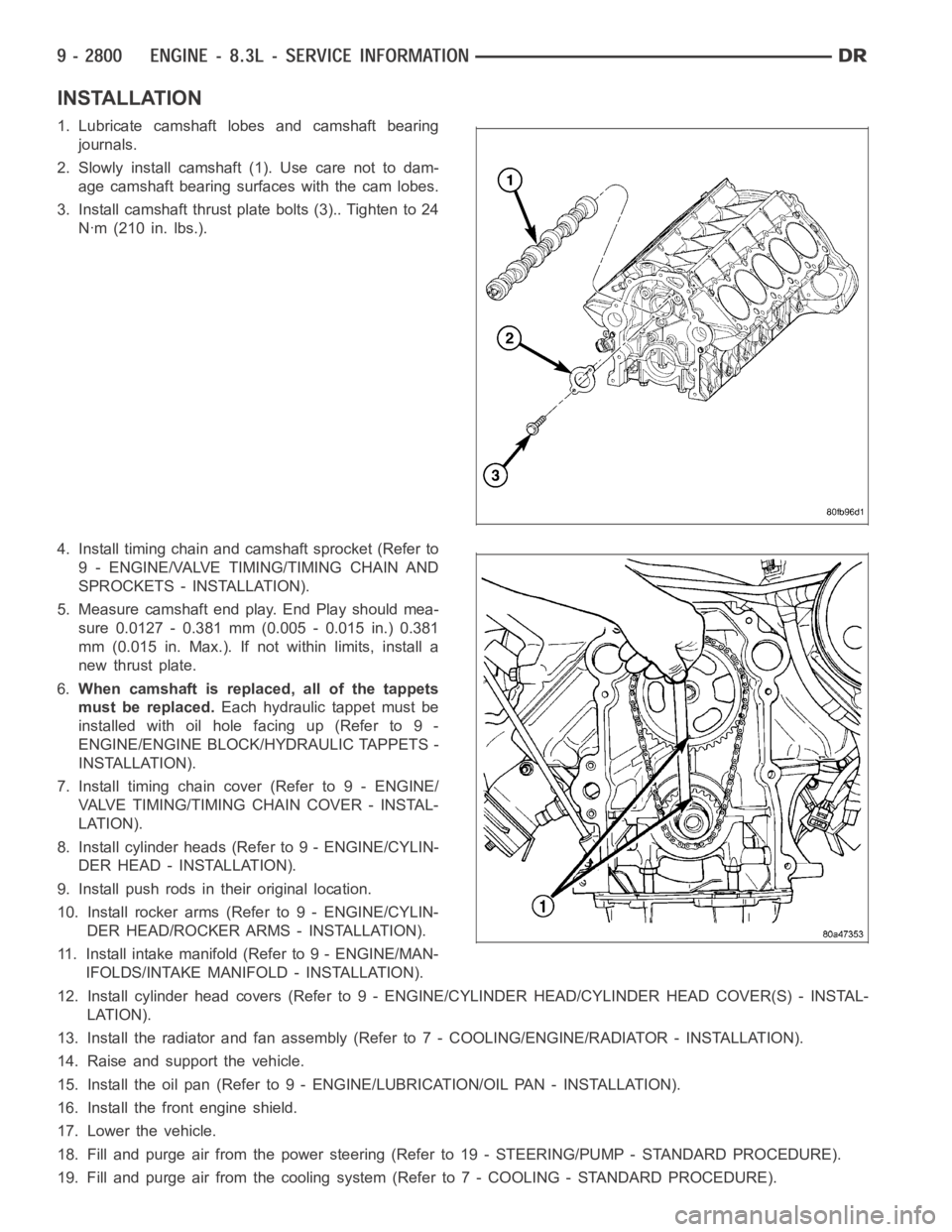
INSTALLATION
1. Lubricate camshaft lobes and camshaft bearing
journals.
2. Slowly install camshaft (1). Use care not to dam-
age camshaft bearing surfaces with the cam lobes.
3. Install camshaft thrust plate bolts (3).. Tighten to 24
Nꞏm (210 in. lbs.).
4. Install timing chain and camshaft sprocket (Refer to
9 - ENGINE/VALVE TIMING/TIMING CHAIN AND
SPROCKETS - INSTALLATION).
5. Measure camshaft end play. End Play should mea-
sure 0.0127 - 0.381 mm (0.005 - 0.015 in.) 0.381
mm (0.015 in. Max.). If not within limits, install a
new thrust plate.
6.When camshaft is replaced, all of the tappets
must be replaced.Each hydraulic tappet must be
installed with oil hole facing up (Refer to 9 -
ENGINE/ENGINE BLOCK/HYDRAULIC TAPPETS -
INSTALLATION).
7. Install timing chain cover (Refer to 9 - ENGINE/
VALVE TIMING/TIMINGCHAIN COVER - INSTAL-
LATION).
8. Install cylinder heads (Refer to 9 - ENGINE/CYLIN-
DER HEAD - INSTALLATION).
9. Install push rods in their original location.
10. Install rocker arms (Refer to 9 - ENGINE/CYLIN-
DER HEAD/ROCKER ARMS - INSTALLATION).
11. Install intake manifold (Refer to 9 - ENGINE/MAN-
IFOLDS/INTAKE MANIFOLD - INSTALLATION).
12. Install cylinder head covers (Refer to 9 - ENGINE/CYLINDER HEAD/CYLINDER HEAD COVER(S) - INSTAL-
LATION).
13. Install the radiator and fan assembly (Refer to 7 - COOLING/ENGINE/RADIATOR - INSTALLATION).
14. Raise and support the vehicle.
15. Install the oil pan (Refer to 9 - ENGINE/LUBRICATION/OIL PAN - INSTALLATION).
16. Install the front engine shield.
17. Lower the vehicle.
18. Fill and purge air from the power steering (Refer to 19 - STEERING/PUMP -STANDARD PROCEDURE).
19. Fill and purge air from the coolingsystem (Refer to 7 - COOLING - STANDARD PROCEDURE).
Page 2243 of 5267
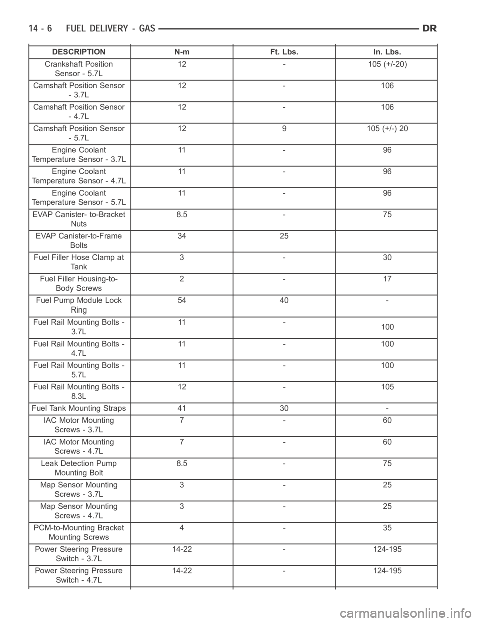
DESCRIPTION N-m Ft. Lbs. In. Lbs.
Crankshaft Position
Sensor - 5.7L12 - 105 (+/-20)
Camshaft Position Sensor
-3.7L12 - 106
Camshaft Position Sensor
-4.7L12 - 106
Camshaft Position Sensor
-5.7L12 9 105 (+/-) 20
Engine Coolant
Temperature Sensor - 3.7L11 - 9 6
Engine Coolant
Temperature Sensor - 4.7L11 - 9 6
Engine Coolant
Temperature Sensor - 5.7L11 - 9 6
EVAP Canister- to-Bracket
Nuts8.5 - 75
EVAP Canister-to-Frame
Bolts34 25
Fuel Filler Hose Clamp at
Tank3-30
Fuel Filler Housing-to-
Body Screws2-17
Fuel Pump Module Lock
Ring54 40 -
Fuel Rail Mounting Bolts -
3.7L11 -
100
Fuel Rail Mounting Bolts -
4.7L11 - 1 0 0
Fuel Rail Mounting Bolts -
5.7L11 - 1 0 0
Fuel Rail Mounting Bolts -
8.3L12 - 105
Fuel Tank Mounting Straps 41 30 -
IAC Motor Mounting
Screws - 3.7L7-60
IAC Motor Mounting
Screws - 4.7L7-60
Leak Detection Pump
Mounting Bolt8.5 - 75
Map Sensor Mounting
Screws - 3.7L3-25
Map Sensor Mounting
Screws - 4.7L3-25
PCM-to-Mounting Bracket
Mounting Screws4-35
Power Steering Pressure
Switch - 3.7L14-22 - 124-195
Power Steering Pressure
Switch - 4.7L14-22 - 124-195
Page 2300 of 5267
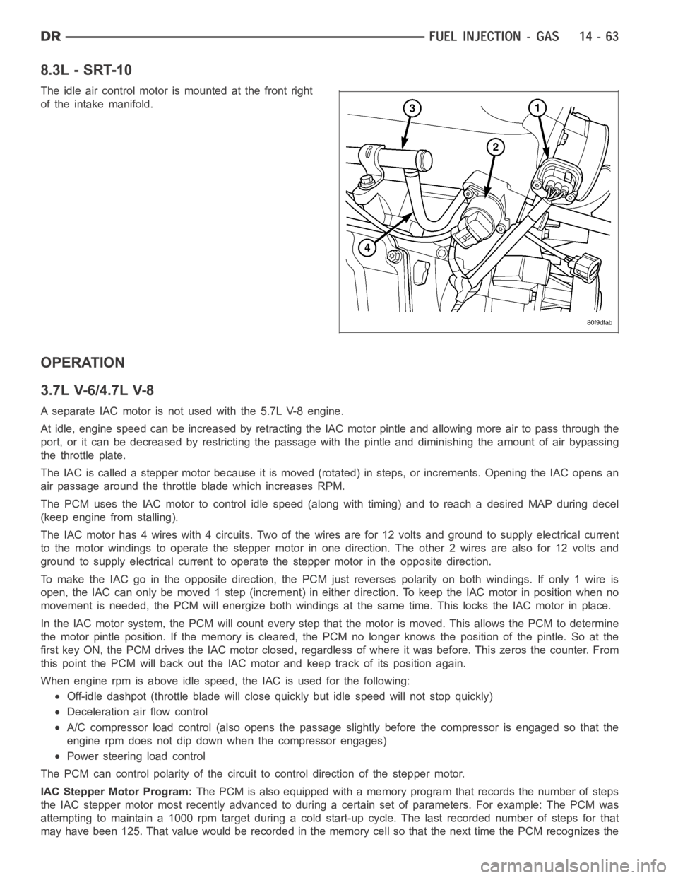
8.3L - SRT-10
The idle air control motor is mounted at the front right
of the intake manifold.
OPERATION
3.7L V-6/4.7L V-8
A separate IAC motor is not used with the 5.7L V-8 engine.
At idle, engine speed can be increased by retracting the IAC motor pintle and allowing more air to pass through the
port, or it can be decreased by restricting the passage with the pintle and diminishing the amount of air bypassing
the throttle plate.
The IAC is called a stepper motor because it is moved (rotated) in steps, or increments. Opening the IAC opens an
air passage around the throttle blade which increases RPM.
The PCM uses the IAC motor to control idle speed (along with timing) and to reach a desired MAP during decel
(keep engine from stalling).
The IAC motor has 4 wires with 4 circuits. Two of the wires are for 12 volts andground to supply electrical current
to the motor windings to operate the stepper motor in one direction. The other2wiresarealsofor12voltsand
ground to supply electrical current to operate the stepper motor in the opposite direction.
To make the IAC go in the opposite direction, the PCM just reverses polarityon both windings. If only 1 wire is
open, the IAC can only be moved 1 step (increment) in either direction. To keeptheIACmotorinpositionwhenno
movement is needed, the PCM will energize both windings at the same time. This locks the IAC motor in place.
In the IAC motor system, the PCM will count every step that the motor is moved. This allows the PCM to determine
the motor pintle position. If the memory is cleared, the PCM no longer knowsthe position of the pintle. So at the
first key ON, the PCM drives the IAC motor closed, regardless of where it wasbefore. This zeros the counter. From
this point the PCM will back out the IAC motor and keep track of its position again.
When engine rpm is above idle speed, the IAC is used for the following:
Off-idle dashpot (throttle blade will close quickly but idle speed will notstopquickly)
Deceleration air flow control
A/C compressor load control (also opens the passage slightly before the compressor is engaged so that the
engine rpm does not dip down when the compressor engages)
Power steering load control
The PCM can control polarity of the circuit to control direction of the stepper motor.
IAC Stepper Motor Program:The PCM is also equipped with a memory program that records the number of steps
the IAC stepper motor most recently advanced to during a certain set of parameters. For example: The PCM was
attempting to maintain a 1000 rpm target during a cold start-up cycle. The last recorded number of steps for that
may have been 125. That value would be recorded in the memory cell so that thenext time the PCM recognizes the
Page 2301 of 5267
identical conditions, the PCM recalls that 125 steps were required to maintain the target. This program allows for
greater customer satisfaction due to greater control of engine idle.
Another function of the memory program, which occurs when the power steering switch (if equipped), or the A/C
request circuit, requires that the IAC stepper motor control engine rpm, is the recording of the last targeted steps
into the memory cell. The PCM can anticipate A/C compressor loads. This is accomplished by delaying compressor
operation for approximately 0.5 seconds until the PCM moves the IAC stepper motor to the recorded steps that
were loaded into the memory cell. Using this program helps eliminate idle-quality changes as loads change. Finally,
the PCM incorporates a
No-Loadengine speed limiter of approximately 1800 - 2000 rpm, when it recognizes that
the TPS is indicating an idle signal and IAC motor cannot maintain engine idle.
A (factory adjusted) set screw is usedto mechanically limit the position of the throttle body throttle plate.Never
attempt to adjust the engine idle speed using this screw.All idle speed functions are controlled by the IAC
motor through the PCM.
REMOVAL
3.7L V-6
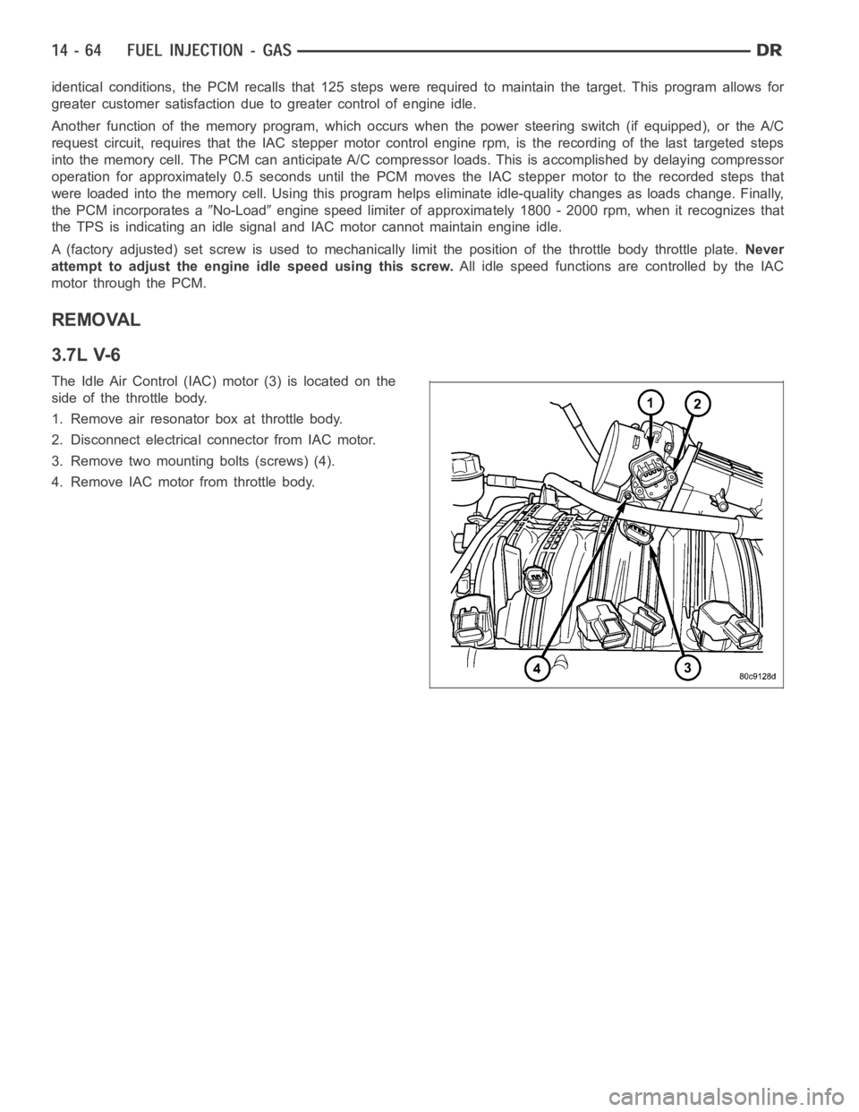
The Idle Air Control (IAC) motor (3) is located on the
side of the throttle body.
1. Remove air resonator box at throttle body.
2. Disconnect electrical connector from IAC motor.
3. Remove two mounting bolts (screws) (4).
4. Remove IAC motor from throttle body.
Page 2406 of 5267
STEERING
TABLE OF CONTENTS
page page
STEERING
DESCRIPTION ................................. 2
OPERATION ................................... 2
DIAGNOSIS AND TESTING
POWER STEERING SYSTEM ................. 2
POWER STEERING FLOW AND PRESSURE . . . 4
SPECIAL TOOLS
STEERING .................................. 6COLUMN...............................7
GEAR - INDEPENDENT FRONT SUSPENSION..38
GEAR - LINK/COIL.......................43
LINKAGE - INDEPENDENT FRONT
SUSPENSION...........................62
LINKAGE - LINK/COIL....................66
PUMP.................................76
PUMP - SRT10..........................92
Page 2407 of 5267
STEERING
DESCRIPTION
CAUTION: MOPARATF+4 is to be used in the power steering system. No other power steering or auto-
matic transmission fluid is to be used in the system. Damage may result to the power steering pump and
system if any other fluid is used, and do not overfill.
Power steering systems consist of:
Steering column
Rack and pinion steering gear
Belt driven hydraulic steering pump
Pump pressure and return hoses
Oil Cooler
OPERATION
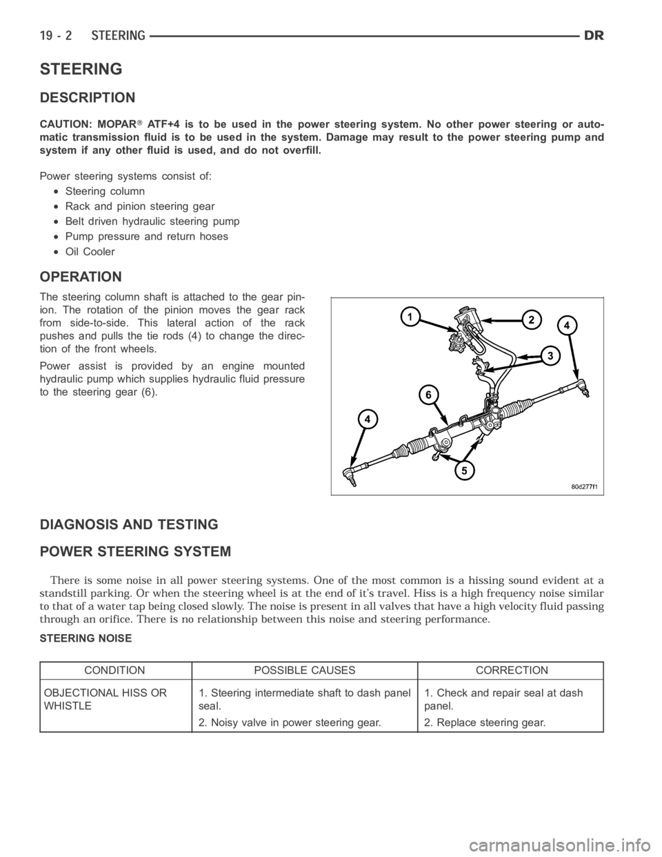
The steering column shaft isattached to the gear pin-
ion. The rotation of the pinion moves the gear rack
from side-to-side. This lateral action of the rack
pushes and pulls the tie rods (4) to change the direc-
tion of the front wheels.
Power assist is provided by an engine mounted
hydraulic pump which supplies hydraulic fluid pressure
to the steering gear (6).
DIAGNOSIS AND TESTING
POWER STEERING SYSTEM
STEERING NOISE
CONDITION POSSIBLE CAUSES CORRECTION
OBJECTIONAL HISS OR
WHISTLE1. Steering intermediate shaft to dash panel
seal.1. Check and repair seal at dash
panel.
2. Noisy valve in power steering gear. 2. Replace steering gear.