2006 DODGE RAM SRT-10 check engine
[x] Cancel search: check enginePage 3392 of 5267
INSTALLATION
1. Check torque converter hub and hub drive flats for
sharp edges burrs, scratches, or nicks. Polish the
hub and flats with 320/400 grit paper and crocus
cloth if necessary. Verify that the converter hub
o-ring is properly installed and is free of any debris.
The hub must be smooth to avoid damaging pump
seal at installation.
2. If a replacement transmission is being installed,
transfer any components necessary, such as the
manual shift lever and shift cable bracket, from the
original transmission onto the replacement trans-
mission.
3. Lubricate oil pump seal lip with transmission fluid.
4. Align converter and oil pump.
5. Carefully insert converter in oil pump. Then rotate
converter back and forth until fully seated in pump
gears.
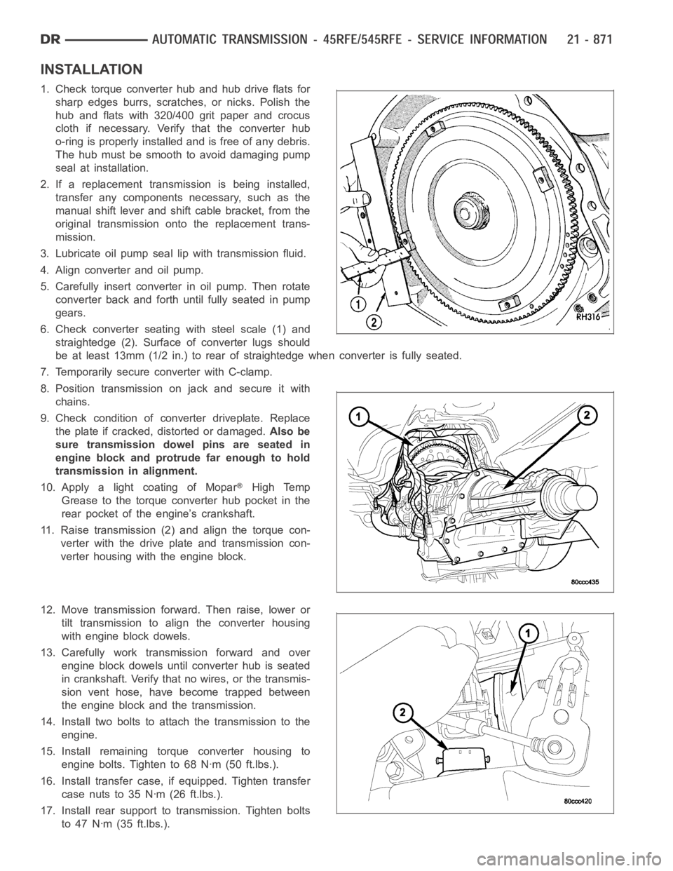
6. Check converter seating with steel scale (1) and
straightedge (2). Surface of converter lugs should
be at least 13mm (1/2 in.) to rear of straightedge when converter is fully seated.
7. Temporarily secure converter with C-clamp.
8. Position transmission on jack and secure it with
chains.
9. Check condition of converter driveplate. Replace
the plate if cracked, distorted or damaged.Also be
sure transmission dowel pins are seated in
engine block and protrude far enough to hold
transmission in alignment.
10. Apply a light coating of Mopar
High Temp
Grease to the torque converter hub pocket in the
rear pocket of the engine’s crankshaft.
11. Raise transmission (2) and align the torque con-
verter with the drive plate and transmission con-
verter housing with the engine block.
12. Move transmission forward. Then raise, lower or
tilt transmission to align the converter housing
with engine block dowels.
13. Carefully work transmission forward and over
engine block dowels until converter hub is seated
in crankshaft. Verify that no wires, or the transmis-
sion vent hose, have become trapped between
theengineblockandthetransmission.
14. Install two bolts to attach the transmission to the
engine.
15. Install remaining torque converter housing to
engine bolts. Tighten to 68 Nꞏm (50 ft.lbs.).
16. Install transfer case, if equipped. Tighten transfer
case nuts to 35 Nꞏm (26 ft.lbs.).
17. Install rear support to transmission. Tighten bolts
to 47 Nꞏm (35 ft.lbs.).
Page 3429 of 5267
ADJUSTMENT PROCEDURE
1. Remove the steering column trim as necessary for
access to the brake transmission shift interlock.
2. Shift the transmission into the PARK position.
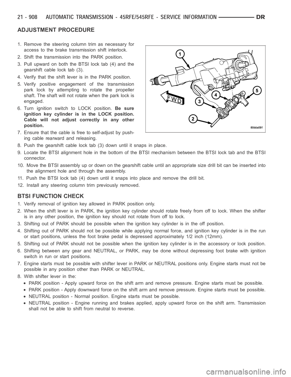
3. Pull upward on both the BTSI lock tab (4) and the
gearshift cable lock tab (3).
4. Verify that the shift lever is in the PARK position.
5. Verify positive engagement of the transmission
park lock by attempting to rotate the propeller
shaft. The shaft will not rotate when the park lock is
engaged.
6. Turn ignition switch to LOCK position.Be sure
ignition key cylinder is in the LOCK position.
Cable will not adjust correctly in any other
position.
7. Ensure that the cable is free to self-adjust by push-
ing cable rearward and releasing.
8. Push the gearshift cable lock tab (3) down until it snaps in place.
9. Locate the BTSI alignment hole in the bottom of the BTSI mechanism betweentheBTSIlocktabandtheBTSI
connector.
10. Move the BTSI assembly up or down on the gearshift cable until an appropriate size drill bit can be inserted into
the alignment hole and through the assembly.
11. Push the BTSI lock tab (4) down until it snaps into place and remove the drill bit.
12. Install any steering column trim previously removed.
BTSI FUNCTION CHECK
1. Verify removal of ignition key allowed in PARK position only.
2. When the shift lever is in PARK, the ignition key cylinder should rotate freely from off to lock. When the shifter
is in any other position, the ignition key should not rotate from off to lock.
3. Shifting out of PARK should be possible when the ignition key cylinder isin the off position.
4. Shifting out of PARK should not be possible while applying normal force,and ignition key cylinder is in the run
or start positions, unless the foot brake pedal is depressed approximately1/2inch(12mm).
5. Shifting out of PARK should not be possible when the ignition key cylinder is in the accessory or lock position.
6. Shifting between any gear and NEUTRAL, or PARK, may be done without depressing foot brake with ignition
switch in run or start positions.
7. Engine starts must be possible with shifter lever in PARK or NEUTRAL positions only. Engine starts must not be
possible in any position other than PARK or NEUTRAL.
8. With shifter lever in the:
PARK position - Apply upward force on the shift arm and remove pressure. Enginestartsmustbepossible.
PARK position - Apply downward force on the shift arm and remove pressure. Engine starts must be possible.
NEUTRAL position - Normal position. Engine starts must be possible.
NEUTRAL position - Engine running and brakes applied, apply upward force on the shift arm. Transmission
shall not be able to shift from neutral to reverse.
Page 3430 of 5267
FLUID AND FILTER
DIAGNOSIS AND TESTING
EFFECTS OF INCORRECT FLUID LEVEL
Alowfluidlevelallowsthepumptotakeinairalongwiththefluid.Airinthe fluid will cause fluid pressures to be
low and develop slower than normal. If the transmission is overfilled, thegears churn the fluid into foam. This aer-
ates the fluid and causing the same conditions occurring with a low level. In either case, air bubbles cause fluid
overheating, oxidation, and varnish buildup which interferes with valveand clutch operation. Foaming also causes
fluid expansion which can result in fluid overflow from the transmission vent or fill tube. Fluid overflow can easily be
mistaken for a leak if inspection is not careful.
CAUSES OF BURNT FLUID
Burnt, discolored fluid is a result of overheating which has three primarycauses.
1. Internal clutch slippage, usually caused by low line pressure, inadequate clutch apply pressure, or clutch seal
failure.
2. A result of restricted fluid flow through the main and/or auxiliary cooler. This condition is usually the result of a
faulty or improperly installed drainback valve, a damaged oil cooler, or severe restrictions in the coolers and lines
caused by debris or kinked lines.
3. Heavy duty operation with a vehicle not properly equipped for this type of operation. Trailer towing or similar high
load operation will overheat the transmission fluid if the vehicle is improperly equipped. Such vehicles should
have an auxiliary transmission fluid cooler, a heavy duty cooling system,and the engine/axle ratio combination
needed to handle heavy loads.
FLUID CONTAMINATION
Transmission fluid contamination is generally a result of:
adding incorrect fluid
failure to clean dipstick and fill tube when checking level
engine coolant entering the fluid
internal failure that generates debris
overheat that generates sludge (fluid breakdown)
failure to replace contaminated converter after repair
The use of non-recommended fluids can result in transmission failure. Theusual results are erratic shifts, slippage,
abnormal wear and eventual failure due to fluid breakdown and sludge formation. Avoid this condition by using rec-
ommended fluids only.
The dipstick cap and fill tube should be wiped clean before checking fluid level. Dirt, grease and other foreign mate-
rial on the cap and tube could fall into the tube if not removed beforehand. Take the time to wipe the cap and tube
clean before withdrawing the dipstick.
Engine coolant in the transmission fluid is generally caused by a cooler malfunction. The only remedy is to replace
the radiator as the cooler in the radiator is not a serviceable part. If coolant has circulated through the transmission,
an overhaul is necessary.
The torque converter should also be replaced whenever a failure generatessludge and debris. This is necessary
because normal converter flushing procedures will not remove all contaminants.
STANDARD PROCEDURE
FLUID LEVEL CHECK
Low fluid level can cause a variety of conditions because it allows the pumpto take in air along with the fluid. As
in any hydraulic system, air bubbles make the fluid spongy, therefore, pressures will be low and build up slowly.
Improper filling can also raise the fluid level too high. When the transmssion has too much fluid, the geartrain
churns up foam and cause the same conditions which occur with a low fluid level.
Page 3431 of 5267

In either case, air bubbles can cause overheating and/or fluid oxidation,and varnishing. This can interfere with nor-
mal valve, clutch, and accumulator operation. Foaming can also result in fluid escaping from the transmission vent
where it may be mistaken for a leak.
After the fluid has been checked, seat the dipstick fully to seal out water and dirt.
The transmission has a dipstick to check oil level. It is located on the right side of the engine. Be sure to wipe all
dirt from dipstick handle before removing.
The torque converter fills in both the P(PARK) and N (NEUTRAL) positions. Place the selector lever in P (PARK)
to be sure that the fluid level check is accurate.The engine should be running at idle speed for at least one
minute, with the vehicle on level ground.At normal operating temperature (approximately 82° C. or 180° F), the
fluid level is correct if it is in the HOT region (cross-hatched area) on theoil level indicator. The fluid level will be
approximately at the upper COLD hole of the dipstick at 21° C (70° F) fluid temperature.
NOTE: Engine and Transmission should be at normal operating temperature before performing this proce-
dure.
1. Start engine and apply parking brake.
2. Shift the transmission into DRIVE for approximately 2 seconds.
3. Shift the transmission into REVERSE for approximately 2 seconds.
4. Shift the transmission into PARK.
5. Hook up scan tool andselect transmission.
6. Select sensors.
7. Read the transmission temperature value.
8. Compare the fluid temperature value with the chart.
9. Adjust transmission fluid level shown on the dipstick according to the Transmission Fluid Temperature Chart.
NOTE: After adding any fluid to the transmission, wait a minimum of 2 minutes for the oil to fully drain from
the fill tube into the transmission before rechecking the fluid level.
10. Check transmission for leaks.
Page 3436 of 5267
ADJUSTMENTS - GEARSHIFT CABLE
Check adjustment by starting the engine in PARK and NEUTRAL. Adjustment isCORRECT if the engine starts only
in these positions. Adjustment is INCORRECT if the engine starts in one butnot both positions. If the engine starts
in any position other than PARK or NEUTRAL, or if the engine will not start atall, the transmission range sensor
may be faulty.
Gearshift Adjustment Procedure
1. Shift transmission into PARK.
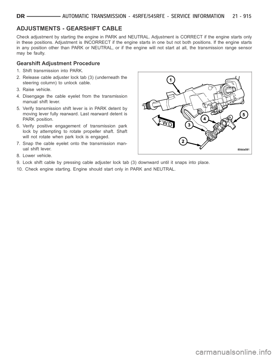
2. Release cable adjuster lock tab (3) (underneath the
steering column) to unlock cable.
3. Raise vehicle.
4. Disengage the cable eyelet from the transmission
manual shift lever.
5. Verify transmission shift lever is in PARK detent by
moving lever fully rearward. Last rearward detent is
PARK position.
6. Verify positive engagement of transmission park
lock by attempting to rotate propeller shaft. Shaft
will not rotate when park lock is engaged.
7. Snap the cable eyelet onto the transmission man-
ual shift lever.
8. Lower vehicle.
9. Lock shift cable by pressing cable adjuster lock tab (3) downward until it snaps into place.
10. Check engine starting. Engine should start only in PARK and NEUTRAL.
Page 3463 of 5267
OPERATION
As the torque converter rotates, the converter hub rotates the oil pump drive gear. As the drive gear rotates both
driven gears, a vacuum is created when the gear teeth come out of mesh. This suction draws fluid through the
pump inlet from the oil pan. As the gear teeth come back into mesh, pressurized fluid is forced into the pump outlet
and to the oil pump valves.
At low speeds, both sides of the pump supply fluid to the transmission. As the speed of the torque converter
increases, the flow from both sides increases until the flow from the primary side alone is sufficient to meet system
demands. At this point, the check valve located between the two pumps closes. The secondary side is shut down
and the primary side supplies all the fluid to the transmission.
CONVERTER CLUTCH SWITCH VALVE
The converter clutch switch valve is used to control the hydraulic pressure supplied to the front (OFF) side of the
torque converter clutch.
CONVERTER CLUTCH REGULATOR VALVE
The converter clutch regulator valve is used to control the hydraulic pressure supplied to the back (ON) side of the
torque converter clutch.
TORQUE CONVERTER LIMIT VALVE
The torque converter limit valve serves to limit the available line pressure to the torque converter clutch.
STANDARD PROCEDURE - OIL PUMP VOLUME CHECK
Measuring the oil pump output volume will determine if sufficient oil flowto the transmission oil cooler exists, and
whether or not an internal transmission failure is present.
Verify that the transmission fluid is at the proper level. Refer to the Fluid Level Check procedure in this section. If
necessary, fill the transmission to the proper level with Mopar
ATF +4, Automatic Transmission Fluid.
1. Disconnect theTo coolerline at the cooler inlet and place a collecting container under the disconnected line.
CAUTION: With the fluid set at the proper level, fluid collection should not exceed (1) quart or internal dam-
age to the transmission may occur.
2. Run the engineat 1800 rpm, with the shift selector in neutral. Verify that the transmission fluid temperature is
below 104.5° C (220° F) for this test.
3. If one quart of transmission fluid is collected in the container in 30 seconds or less, oil pump flow volume is
within acceptable limits. If fluid flow is intermittent, or it takes more than 30 seconds to collect one quart of fluid,
refer to the Hydraulic Pressure tests in this section for further diagnosis.
4. Re-connect theTo c o o l e rline to the transmission cooler inlet.
5. Refill the transmission to proper level.
Page 3511 of 5267
Theory of Operation
The Transmission Temperature Sensor is used to sense when the transmissiontemperatureistoohotortoocoldto
operate overdrive and/or the torque convertor clutch. When the transmission sensor detects a temperature below 0°
C (32° F), overdrive and the torque convertor clutch are disabled. When thedetected temperature is above 127° C
(260° F), overdrive is disabled and 3rd gear with TCC is engaged, this strategy is used to increase transmission
fluid flow to help cool the transmission.
When Monitored:
Continuously with the ignition on and the engine running.
Set Condition:
The DTC will set after two consecutive trips in which the transmission oil temperature is greater than 5° C (40°
F) and the transmission oil temperature does not rise more than 8° C (16° F) after 20 minutes of run time with
a vehicle speed greater than 48 Kmh (30 mph). The DTC will also set if the engine temperature is greater than
38° C (100° F) with the transmission oil temperature greater than 127° C (260° F).
Possible Causes
OTHER TRANSMISSION DTC’S SET
INTERMITTENT TRANSMISSION TEMPERATURE SENSOR
TRANSMISSION TEMPERATURE SENSOR
Always perform the Pre-Diagnostic Troubleshooting procedure before proceeding. (Refer to 21 - TRANSMIS-
SION/TRANSAXLE/AUTOMATIC - 48RE - STANDARD PROCEDURE)
Diagnostic Test
1.CHECK IF THE DTC IS CURRENT
Ignition on, engine not running.
With the scan tool, read Engine DTCs.
Record the Freeze Frame data for the reported DTC.
With the scan tool, erase DTCs.
Turn the ignition off to the lock position.
Using the Freeze Frame data recorded earlier, try to duplicate the conditions in which the DTC originally set.
NOTE: It may be necessary to road test the vehicle to duplicate the originalset conditions.
With the scan tool, read Engine DTCs.
Did the DTC reset?
Ye s>>
Go To 2
No>>
Go To 6
2.CHECK FOR OTHER TRANSMISSION DTCS
Does the scan tool show any Park/Neutral DTCs?
Ye s>>
Refer to the Transmission category and perform the appropriate symptom(s).
No>>
Go To 3
Page 3512 of 5267

3.COMPARE THE TRANSMISSION TEMPERATURE TO ENGINE COOLANT TEMPERATURE
NOTE: To test the transmission temperature sensor, the engine and transmission temperature must be at or
below 29.4° C (85° F).
With the scan tool, read the Transmission and Engine temperatures.
Is the transmission temperature within 5° C (9° F) of the engine coolant temperature?
Ye s>>
Go To 4
No>>
Go To 5
4.CHECK IF THE TRANSMISSION TEMPERATURE INCREASES 15 DEGREES OVER 10 MINUTEPERIOD
NOTE: To test the transmission temperature sensor, the engine and transmission temperature must be at or
below 29.4° C (85° F).
CAUTION: Apply the parking brake.
Start the engine, firmly apply the brakes and allow the engine to idle in Drive.
With the scan tool, monitor the Transmission Temperature.
NOTE: If the transmission temperature sensor is working properly, the transmission temperature should rise
at least 8° C (15° F) within a ten minute period.
Did the transmission temperature increase at a steady rate and rise at least 8° C (15° F) over a 10
minute period?
Ye s>>
Go To 6
No>>
Go To 5
5.CHECK THE TRANSMISSION TEMPERATURE SENSOR
TYPICAL VALUES FOR TRANSMISSION TEMPERATURE SENSOR
TEMPERATURE MIN TO MAX OHM RANGE
-40° C (-40° F) 1094 to 1176 ohms
0.0° C (32° F) 1587 to 1672 ohms
25° C (77° F) 1960 to 2040 ohms
70° C (158° F) 2709 to 2860 ohms
0° C (212° F) 3284 to 3500 ohms
120° C (120° F) 3684 to 3950 ohms
150° C (302° F) 4110 to 4450 ohms