2006 DODGE RAM SRT-10 check engine
[x] Cancel search: check enginePage 3548 of 5267
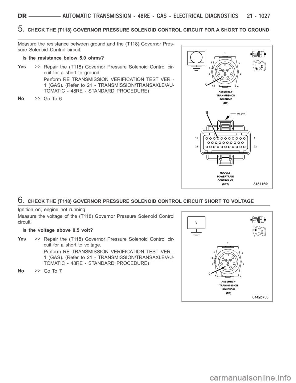
5.CHECK THE (T118) GOVERNOR PRESSURE SOLENOID CONTROL CIRCUIT FOR A SHORT TOGROUND
Measure the resistance between ground and the (T118) Governor Pres-
sure Solenoid Control circuit.
Is the resistance below 5.0 ohms?
Ye s>>
Repair the (T118) Governor Pressure Solenoid Control cir-
cuit for a short to ground.
Perform RE TRANSMISSION VERIFICATION TEST VER -
1 (GAS). (Refer to 21 - TRANSMISSION/TRANSAXLE/AU-
TOMATIC - 48RE - STANDARD PROCEDURE)
No>>
Go To 6
6.CHECK THE (T118) GOVERNOR PRESSURE SOLENOID CONTROL CIRCUIT SHORT TO VOLTAGE
Ignition on, engine not running.
Measure the voltage of the (T118) Governor Pressure Solenoid Control
circuit.
Is the voltage above 0.5 volt?
Ye s>>
Repair the (T118) Governor Pressure Solenoid Control cir-
cuit for a short to voltage.
Perform RE TRANSMISSION VERIFICATION TEST VER -
1 (GAS). (Refer to 21 - TRANSMISSION/TRANSAXLE/AU-
TOMATIC - 48RE - STANDARD PROCEDURE)
No>>
Go To 7
Page 3550 of 5267
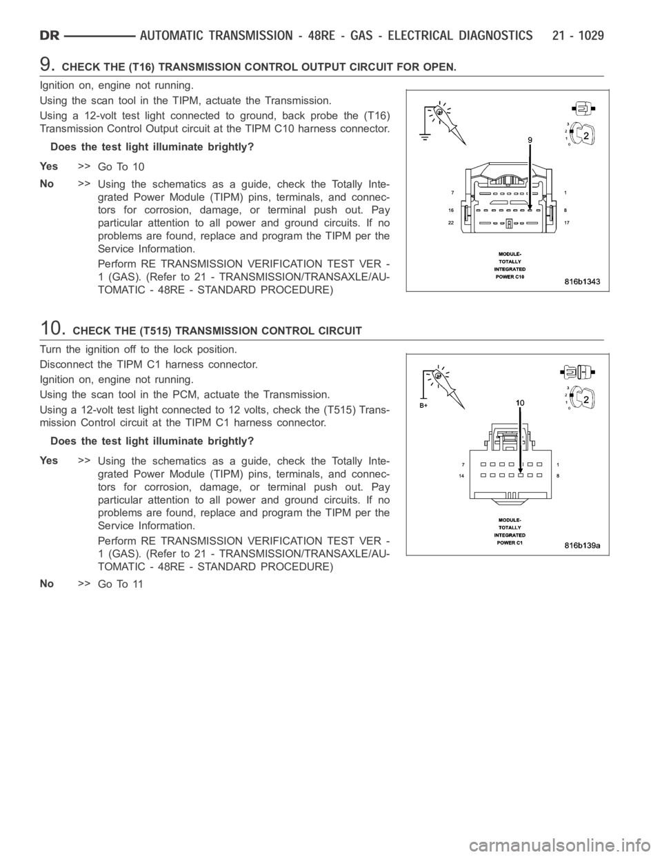
9.CHECK THE (T16) TRANSMISSION CONTROL OUTPUT CIRCUIT FOR OPEN.
Ignition on, engine not running.
Using the scan tool in the TIPM, actuate the Transmission.
Using a 12-volt test light connected to ground, back probe the (T16)
Transmission Control Output circuit at the TIPM C10 harness connector.
Does the test light illuminate brightly?
Ye s>>
Go To 10
No>>
Using the schematics as a guide, check the Totally Inte-
grated Power Module (TIPM) pins, terminals, and connec-
tors for corrosion, damage, or terminal push out. Pay
particular attention to all power and ground circuits. If no
problems are found, replace and program the TIPM per the
Service Information.
Perform RE TRANSMISSION VERIFICATION TEST VER -
1 (GAS). (Refer to 21 - TRANSMISSION/TRANSAXLE/AU-
TOMATIC - 48RE - STANDARD PROCEDURE)
10.CHECK THE (T515) TRANSMISSION CONTROL CIRCUIT
Turn the ignition off to the lock position.
Disconnect the TIPM C1 harness connector.
Ignition on, engine not running.
Using the scan tool in the PCM, actuate the Transmission.
Using a 12-volt test light connected to 12 volts, check the (T515) Trans-
mission Control circuit at the TIPM C1 harness connector.
Does the test light illuminate brightly?
Ye s>>
Using the schematics as a guide, check the Totally Inte-
grated Power Module (TIPM) pins, terminals, and connec-
tors for corrosion, damage, or terminal push out. Pay
particular attention to all power and ground circuits. If no
problems are found, replace and program the TIPM per the
Service Information.
Perform RE TRANSMISSION VERIFICATION TEST VER -
1 (GAS). (Refer to 21 - TRANSMISSION/TRANSAXLE/AU-
TOMATIC - 48RE - STANDARD PROCEDURE)
No>>
Go To 11
Page 3551 of 5267
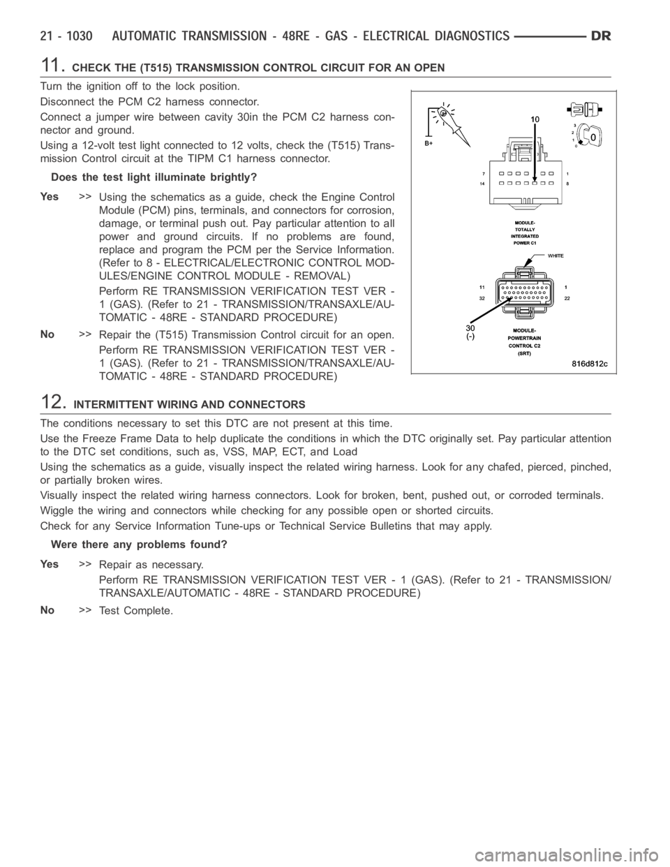
11 .CHECK THE (T515) TRANSMISSION CONTROL CIRCUIT FOR AN OPEN
Turn the ignition off to the lock position.
Disconnect the PCM C2 harness connector.
Connect a jumper wire between cavity 30in the PCM C2 harness con-
nector and ground.
Using a 12-volt test light connected to 12 volts, check the (T515) Trans-
mission Control circuit at the TIPM C1 harness connector.
Does the test light illuminate brightly?
Ye s>>
Using the schematics as a guide, check the Engine Control
Module (PCM) pins, terminals, and connectors for corrosion,
damage, or terminal push out. Pay particular attention to all
power and ground circuits. If no problems are found,
replace and program the PCM per the Service Information.
(Refer to 8 - ELECTRICAL/ELECTRONIC CONTROL MOD-
ULES/ENGINE CONTROL MODULE - REMOVAL)
Perform RE TRANSMISSION VERIFICATION TEST VER -
1 (GAS). (Refer to 21 - TRANSMISSION/TRANSAXLE/AU-
TOMATIC - 48RE - STANDARD PROCEDURE)
No>>
Repair the (T515) Transmission Control circuit for an open.
Perform RE TRANSMISSION VERIFICATION TEST VER -
1 (GAS). (Refer to 21 - TRANSMISSION/TRANSAXLE/AU-
TOMATIC - 48RE - STANDARD PROCEDURE)
12.INTERMITTENT WIRING AND CONNECTORS
The conditions necessary to set this DTC are not present at this time.
Use the Freeze Frame Data to help duplicate the conditions in which the DTC originally set. Pay particular attention
to the DTC set conditions, such as, VSS, MAP, ECT, and Load
Using the schematics as a guide, visually inspect the related wiring harness. Look for any chafed, pierced, pinched,
or partially broken wires.
Visually inspect the related wiring harness connectors. Look for broken,bent, pushed out, or corroded terminals.
Wiggle the wiring and connectors while checking for any possible open or shorted circuits.
Check for any Service Information Tune-ups or Technical Service Bulletins that may apply.
Were there any problems found?
Ye s>>
Repair as necessary.
Perform RE TRANSMISSION VERIFICATION TEST VER - 1 (GAS). (Refer to 21 - TRANSMISSION/
TRANSAXLE/AUTOMATIC - 48RE - STANDARD PROCEDURE)
No>>
Te s t C o m p l e t e .
Page 3556 of 5267
Theory of Operation
The 3-4 Solenoid is used the engage the gear change form 3rd gear to 4th gear.
The solenoids used in transmission applications are attached to valves which can be classified as normally open or
normally closed. The normally open solenoid valve is defined as a valve which allows hydraulic flow when no cur-
rent or voltage is applied to the solenoid. The normally closed solenoid valve is defined as a valve which does not
allow hydraulic flow when no current or voltage is applied to the solenoid.These valves perform hydraulic control
functions for the transmission and must therefore be durable and tolerantof dirt particles. For these reasons, the
valves have hardened steel poppets and ball valves. The solenoids operatethe valves directly, which means that
the solenoids must have very high outputs to close the valves against the sizable flow areas and line pressures
found in current transmissions. Fastresponse time is also necessary to ensure accurate control.
When Monitored:
Continuously with ignition on.
Set Condition:
This DTC will set if the voltage detected on the 3-4 Shift Solenoid Control circuit at the PCM is different then
the expected voltage. Note: To clear this DTC it is necessary to drive the vehicle at a sustained speed which
would allow the TCC and/or Overdrive Clutch to operate
Possible Causes
TRANSMISSION CONTROL OUTPUT DTC PRESENT
(T9) 3-4 SOLENOID CONTROL CIRCUIT OPEN
(T16) TRANSMISSION CONTROL OUTPUT CIRCUIT OPEN
(T9) 3-4 SOLENOID CONTROL CIRCUIT SHORT TO VOLTAGE
(T9) 3-4 SOLENOID CONTROL CIRCUIT SHORT TO GROUND
(T16) TRANSMISSION RELAY OUTPUT CIRCUIT SHORT TO GROUND
(T9) 3-4 SOLENOID CIRCUIT SHORT TO OTHER CIRCUITS
TOTALLY INTEGRATED POWER MODULE
3-4 SHIFT SOLENOID
POWERTRAIN CONTROL MODULE
Always perform the Pre-Diagnostic Troubleshooting procedure before proceeding. (Refer to 21 - TRANSMIS-
SION/TRANSAXLE/AUTOMATIC - 48RE - STANDARD PROCEDURE)
Diagnostic Test
1.CHECK IF THERE ANY TRANSMISSION CONTROL DTCS PRESENT
Ignition on, engine not running.
With the scan tool, read Engine DTCs.
Are there any TIPM TCM Power Control Circuit DTCs also present?
Ye s>>
Refer to the Transmission category, and perform the appropriate symptom(s).
No>>
Go To 2
Page 3557 of 5267
2.CHECK IF THE DTC IS CURRENT
Ignition on, engine not running.
With the scan tool, read Engine DTCs.
Record the Freeze Frame data for the reported DTC.
With the scan tool, erase DTCs.
Turn the ignition off to the lock position.
Using the Freeze Frame data recorded earlier, try to duplicate the conditions in which the DTC originally set.
NOTE: It may be necessary to road test the vehicle to duplicate the originalset conditions.
With the scan tool, read Engine DTCs.
Did the DTC reset?
Ye s>>
Go To 3
No>>
Go To 12
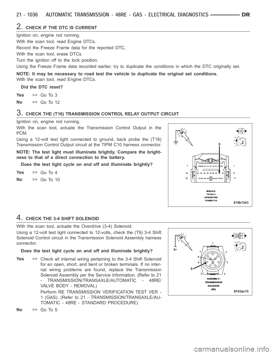
3.CHECK THE (T16) TRANSMISSION CONTROL RELAY OUTPUT CIRCUIT
Ignition on, engine not running.
With the scan tool, actuate the Transmission Control Output in the
PCM.
Using a 12-volt test light connected to ground, back probe the (T16)
Transmission Control Output circuit at the TIPM C10 harness connector.
NOTE: The test light must illuminate brightly. Compare the bright-
ness to that of a direct connection to the battery.
Does the test light cycle on and off and illuminate brightly?
Ye s>>
Go To 4
No>>
Go To 10
4.CHECK THE 3-4 SHIFT SOLENOID
With the scan tool, actuate the Overdrive (3-4) Solenoid.
Using a 12-volt test light connected to 12-volts, check the (T9) 3-4 Shift
Solenoid Control circuit in the Transmission Solenoid Assembly harness
connector.
Does the test light cycle on and off and illuminate brightly?
Ye s>>
Check all internal wiring pertaining to the 3-4 Shift Solenoid
for an open, short, and bent or broken terminals. If no inter-
nal wiring problems are found, replace the Transmission
Solenoid Assembly per the Service Information. (Refer to 21
- TRANSMISSION/TRANSAXLE/AUTOMATIC - 48RE/
VA LV E B O D Y - R E M O VA L )
Perform RE TRANSMISSION VERIFICATION TEST VER -
1 (GAS). (Refer to 21 - TRANSMISSION/TRANSAXLE/AU-
TOMATIC - 48RE - STANDARD PROCEDURE)
No>>
Go To 5
Page 3558 of 5267
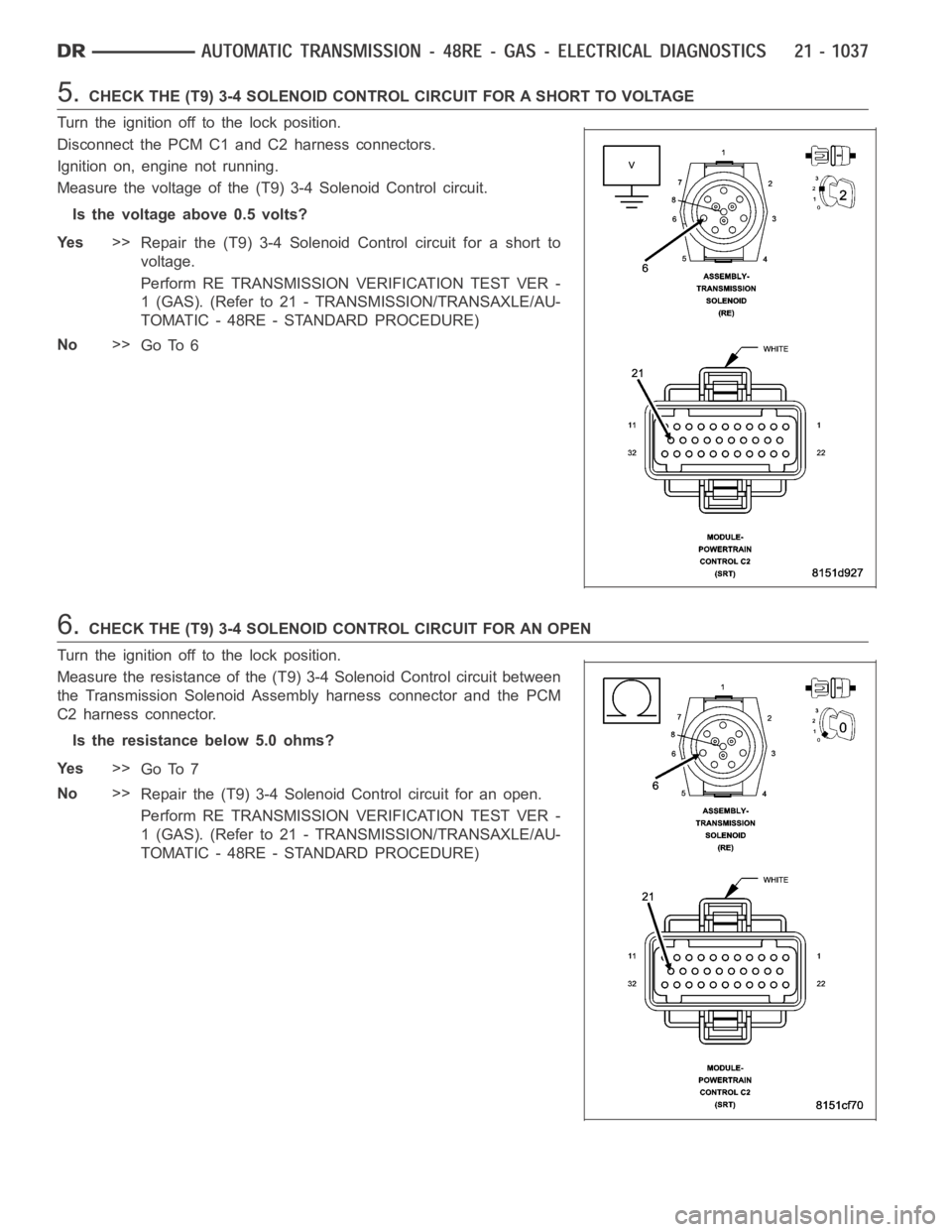
5.CHECK THE (T9) 3-4 SOLENOID CONTROL CIRCUIT FOR A SHORT TO VOLTAGE
Turn the ignition off to the lock position.
Disconnect the PCM C1 and C2 harness connectors.
Ignition on, engine not running.
Measure the voltage of the (T9) 3-4 Solenoid Control circuit.
Is the voltage above 0.5 volts?
Ye s>>
Repair the (T9) 3-4 Solenoid Control circuit for a short to
voltage.
Perform RE TRANSMISSION VERIFICATION TEST VER -
1 (GAS). (Refer to 21 - TRANSMISSION/TRANSAXLE/AU-
TOMATIC - 48RE - STANDARD PROCEDURE)
No>>
Go To 6
6.CHECK THE (T9) 3-4 SOLENOID CONTROL CIRCUIT FOR AN OPEN
Turn the ignition off to the lock position.
Measure the resistance of the (T9) 3-4 Solenoid Control circuit between
the Transmission Solenoid Assembly harness connector and the PCM
C2 harness connector.
Is the resistance below 5.0 ohms?
Ye s>>
Go To 7
No>>
Repair the (T9) 3-4 Solenoid Control circuit for an open.
Perform RE TRANSMISSION VERIFICATION TEST VER -
1 (GAS). (Refer to 21 - TRANSMISSION/TRANSAXLE/AU-
TOMATIC - 48RE - STANDARD PROCEDURE)
Page 3560 of 5267
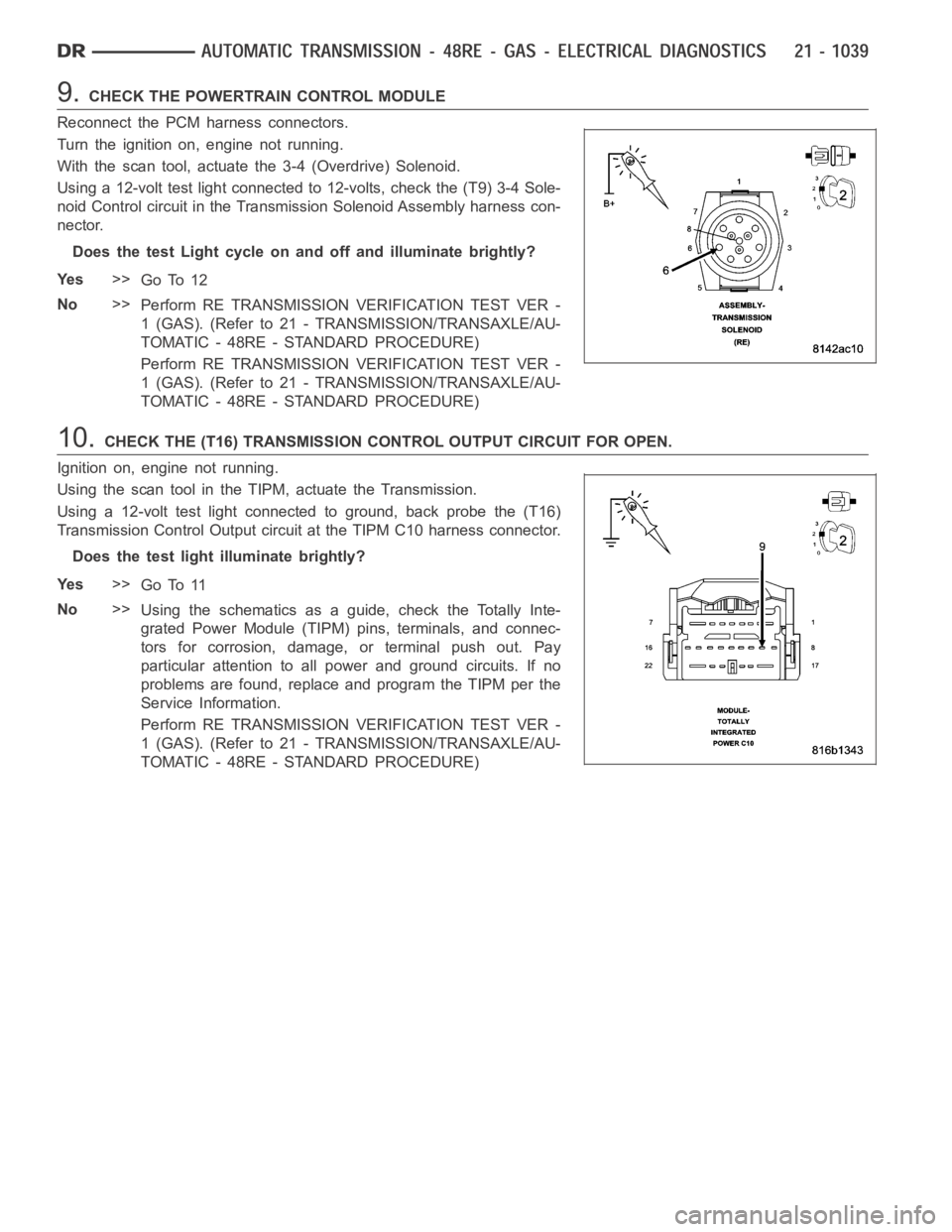
9.CHECK THE POWERTRAIN CONTROL MODULE
Reconnect the PCM harness connectors.
Turn the ignition on, engine not running.
With the scan tool, actuate the 3-4 (Overdrive) Solenoid.
Using a 12-volt test light connected to 12-volts, check the (T9) 3-4 Sole-
noid Control circuit in the Transmission Solenoid Assembly harness con-
nector.
Does the test Light cycle on and off and illuminate brightly?
Ye s>>
Go To 12
No>>
Perform RE TRANSMISSION VERIFICATION TEST VER -
1 (GAS). (Refer to 21 - TRANSMISSION/TRANSAXLE/AU-
TOMATIC - 48RE - STANDARD PROCEDURE)
Perform RE TRANSMISSION VERIFICATION TEST VER -
1 (GAS). (Refer to 21 - TRANSMISSION/TRANSAXLE/AU-
TOMATIC - 48RE - STANDARD PROCEDURE)
10.CHECK THE (T16) TRANSMISSION CONTROL OUTPUT CIRCUIT FOR OPEN.
Ignition on, engine not running.
Using the scan tool in the TIPM, actuate the Transmission.
Using a 12-volt test light connected to ground, back probe the (T16)
Transmission Control Output circuit at the TIPM C10 harness connector.
Does the test light illuminate brightly?
Ye s>>
Go To 11
No>>
Using the schematics as a guide, check the Totally Inte-
grated Power Module (TIPM) pins, terminals, and connec-
tors for corrosion, damage, or terminal push out. Pay
particular attention to all power and ground circuits. If no
problems are found, replace and program the TIPM per the
Service Information.
Perform RE TRANSMISSION VERIFICATION TEST VER -
1 (GAS). (Refer to 21 - TRANSMISSION/TRANSAXLE/AU-
TOMATIC - 48RE - STANDARD PROCEDURE)
Page 3561 of 5267
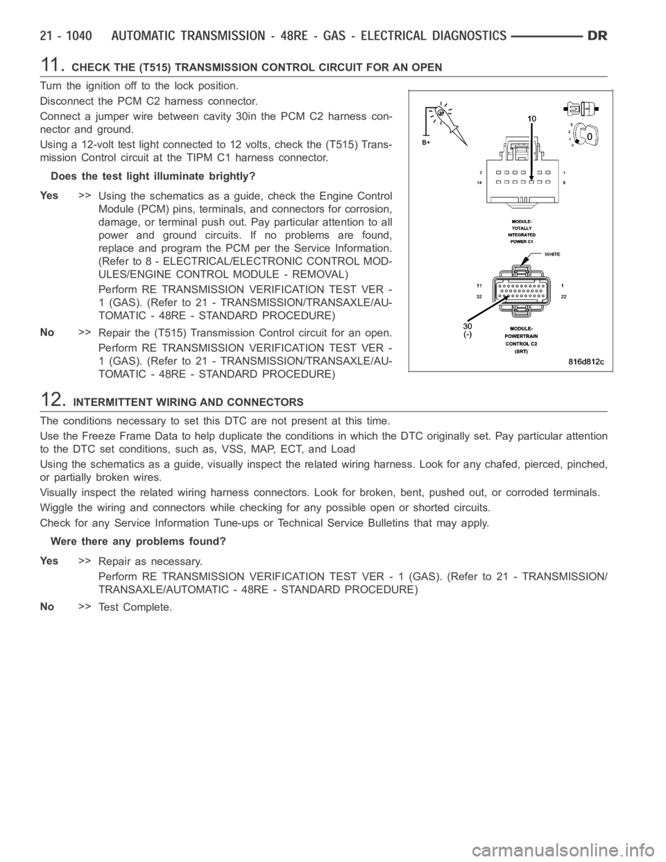
11 .CHECK THE (T515) TRANSMISSION CONTROL CIRCUIT FOR AN OPEN
Turn the ignition off to the lock position.
Disconnect the PCM C2 harness connector.
Connect a jumper wire between cavity 30in the PCM C2 harness con-
nector and ground.
Using a 12-volt test light connected to 12 volts, check the (T515) Trans-
mission Control circuit at the TIPM C1 harness connector.
Does the test light illuminate brightly?
Ye s>>
Using the schematics as a guide, check the Engine Control
Module (PCM) pins, terminals, and connectors for corrosion,
damage, or terminal push out. Pay particular attention to all
power and ground circuits. If no problems are found,
replace and program the PCM per the Service Information.
(Refer to 8 - ELECTRICAL/ELECTRONIC CONTROL MOD-
ULES/ENGINE CONTROL MODULE - REMOVAL)
Perform RE TRANSMISSION VERIFICATION TEST VER -
1 (GAS). (Refer to 21 - TRANSMISSION/TRANSAXLE/AU-
TOMATIC - 48RE - STANDARD PROCEDURE)
No>>
Repair the (T515) Transmission Control circuit for an open.
Perform RE TRANSMISSION VERIFICATION TEST VER -
1 (GAS). (Refer to 21 - TRANSMISSION/TRANSAXLE/AU-
TOMATIC - 48RE - STANDARD PROCEDURE)
12.INTERMITTENT WIRING AND CONNECTORS
The conditions necessary to set this DTC are not present at this time.
Use the Freeze Frame Data to help duplicate the conditions in which the DTC originally set. Pay particular attention
to the DTC set conditions, such as, VSS, MAP, ECT, and Load
Using the schematics as a guide, visually inspect the related wiring harness. Look for any chafed, pierced, pinched,
or partially broken wires.
Visually inspect the related wiring harness connectors. Look for broken,bent, pushed out, or corroded terminals.
Wiggle the wiring and connectors while checking for any possible open or shorted circuits.
Check for any Service Information Tune-ups or Technical Service Bulletins that may apply.
Were there any problems found?
Ye s>>
Repair as necessary.
Perform RE TRANSMISSION VERIFICATION TEST VER - 1 (GAS). (Refer to 21 - TRANSMISSION/
TRANSAXLE/AUTOMATIC - 48RE - STANDARD PROCEDURE)
No>>
Te s t C o m p l e t e .