2006 DODGE RAM SRT-10 light
[x] Cancel search: lightPage 352 of 5267

3.EXCESSIVE RESISTANCE IN THE CASE GROUND
WARNING: When the engine is operating, do not stand in direct line with the fan. Do not put your hands
near the pulleys, belts, or fan. Do notwear loose clothing. Failure to follow these instructions can result in
personal injury or death.
Start the engine.
Warm the engine to operating temperature.
NOTE: Make sure all wires are clear of the engine’s moving parts.
Measure the voltage between the Generator Case and Battery ground post.
Is the voltage above 0.1 of a volt?
Ye s>>
Repair the excessive resistance in the Generator Case Ground.
Perform the POWERTRAIN VERIFICATION TEST. (Refer to 9 - ENGINE - STANDARD PROCEDURE)
No>>
Go To 4
4.GENERATOR OPERATION
Turn the ignition off.
Disconnect the Generator Field harness connector.
Using a 12-volt test light, jump across the Generator Field harness con-
nector.
Ignition on, engine not running.
With a scan tool, actuate theGenerator Field Driver.
Does the test light illuminate brightly and flash on and off?
Ye s>>
Replace the Generator.
Perform the POWERTRAIN VERIFICATION TEST. (Refer to
9 - ENGINE - STANDARD PROCEDURE)
No>>
Go To 5
5.(K20) GEN FIELD CONTROL CIRCUIT SHORTED TO BATTERY VOLTAGE
Turn the ignition off.
Disconnect the C2 PCM harness connector.
Ignition on, engine not running.
Measure the voltage on the (K20) Gen Field Control circuit in the Gen-
erator Field harness connector.
Is the voltage above 1.0 volt?
Ye s>>
Repair the short to battery voltage in the (K20) Gen Field
Control circuit.
Perform the POWERTRAIN VERIFICATION TEST. (Refer to
9 - ENGINE - STANDARD PROCEDURE)
No>>
Go To 6
Page 353 of 5267
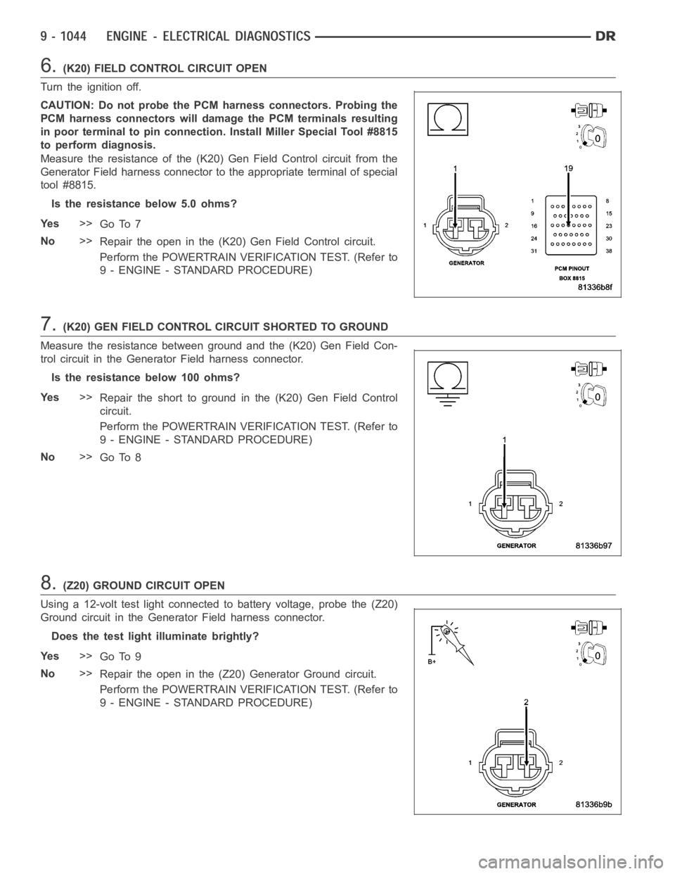
6.(K20) FIELD CONTROL CIRCUIT OPEN
Turn the ignition off.
CAUTION: Do not probe the PCM harness connectors. Probing the
PCM harness connectors will damage the PCM terminals resulting
in poor terminal to pin connection. Install Miller Special Tool #8815
to perform diagnosis.
Measure the resistance of the (K20) Gen Field Control circuit from the
Generator Field harness connector to the appropriate terminal of special
tool #8815.
Is the resistance below 5.0 ohms?
Ye s>>
Go To 7
No>>
Repair the open in the (K20) Gen Field Control circuit.
Perform the POWERTRAIN VERIFICATION TEST. (Refer to
9 - ENGINE - STANDARD PROCEDURE)
7.(K20) GEN FIELD CONTROL CIRCUIT SHORTED TO GROUND
Measure the resistance between ground and the (K20) Gen Field Con-
trol circuit in the Generator Field harness connector.
Istheresistancebelow100ohms?
Ye s>>
Repair the short to ground in the (K20) Gen Field Control
circuit.
Perform the POWERTRAIN VERIFICATION TEST. (Refer to
9 - ENGINE - STANDARD PROCEDURE)
No>>
Go To 8
8.(Z20) GROUND CIRCUIT OPEN
Using a 12-volt test light connected to battery voltage, probe the (Z20)
Ground circuit in the Generator Field harness connector.
Does the test light illuminate brightly?
Ye s>>
Go To 9
No>>
Repair the open in the (Z20) Generator Ground circuit.
Perform the POWERTRAIN VERIFICATION TEST. (Refer to
9 - ENGINE - STANDARD PROCEDURE)
Page 355 of 5267

P2610-PCM INTERNAL SHUTDOWN TIMER FAST RATIONALITY
For a complete wiring diagramRefer to Section 8W.
When Monitored:
Ignition on and battery voltage greater than 10 volts.
Set Condition:
Internal PCM failure detected. One Trip Fault. Three good trips to turn offthe MIL.
Possible Causes
PCM FUSED IGNITION SWITCH CIRCUIT
PCM INTERNAL
Always perform the Pre-Diagnostic Troubleshooting procedure before proceeding. (Refer to 9 - ENGINE -
DIAGNOSIS AND TESTING).
Diagnostic Test
1.PCM IGNITION CIRCUITS
Turn the ignition off.
Disconnect the C1 PCM harness connector.
CAUTION: Do not probe the PCM harness connectors. Probing the
PCM harness connectors will damage the PCM terminals resulting
in poor terminal to pin connection. Install Miller Special Tool #8815
to perform diagnosis.
With a 12-volt test light connected to ground and with special tool
#8815 installed, probe the (F202), (F1), and (T751) Fused Ignition
Switch circuits.
Perform the above check with the Ignition key in the off lock position,
Ignition on, engine not running position, and during cranking.
Wiggle the related wire harness while probing the special tool with the
test light to try to interrupt the circuit.
Does the test light illuminate brightly?
Ye s>>
Go To 2
No>>
Repair the open or excessive resistance in the (F202), (F1), and (T751) Fused Ignition Switch (Off, Run,
Start) circuits. Inspect the related fuse, if the fuse is open check the circuits for a short to ground.
Perform the POWERTRAIN VERIFICATION TEST. (Refer to 9 - ENGINE - STANDARD PROCEDURE)
2.PCM
The Powertrain Control Module is reporting internal errors.
NOTE: Before continuing, check the PCM harness connector terminals for corrosion, damage, or terminal
push out. Repair as necessary.
Using the schematics as a guide, inspect the wire harness and connectors. Pay particular attention to all Power and
Ground circuits.
Were there any problems found?
Ye s>>
Repair as necessary.
Perform the POWERTRAIN VERIFICATION TEST. (Refer to 9 - ENGINE - STANDARD PROCEDURE)
No>>
Replace and program the Powertrain Control Module per Service Information.
Perform the POWERTRAIN VERIFICATION TEST. (Refer to 9 - ENGINE - STANDARD PROCEDURE)
Page 359 of 5267
For a complete wiring diagramRefer to Section 8W.
Theory of Operation
When all criteria has been met, power is supplied to each MDS Solenoid when the engine is making a transition
from 8 cylinder mode to 4 cylinder mode. By actuating the solenoid, oil pressure is raised to the pair of lifters that
coincide with each particular solenoid. The oil pressure pushes in the locking pins that allows the lifter to collapse,
decoupling the valves and camshaft.
When Monitored:
Transition from 8 to 4 cylinder mode.
Set Condition:
When the PCM recognizes a problem with the Solenoid Control circuit. One trip fault.
Possible Causes
(K451) MDS SOLENOID NO.1 CONTROL SHORT TO BATTERY VOLTAGE
(K451) MDS SOLENOID NO.1 CONTROL SHORT TO GROUND
(K451) MDS SOLENOID NO.1 CONTROL OPEN
(Z903) GROUND CIRCUIT OPEN
MDS SOLENOID NO.1
PCM
Always perform the Pre-Diagnostic Troubleshooting procedure before proceeding. (Refer to 9 - ENGINE -
DIAGNOSIS AND TESTING).
Diagnostic Test
1.ACTIVE DTC
Ignition on, engine not running.
With a scan tool, read DTCs.
Is the DTC active at this time?
Ye s>>
Go To 2
No>>
Refer to the INTERMITTENT CONDITION Diagnostic Procedure.
Perform the POWERTRAIN VERIFICATION TEST. (Refer to 9 - ENGINE - STANDARD PROCEDURE)
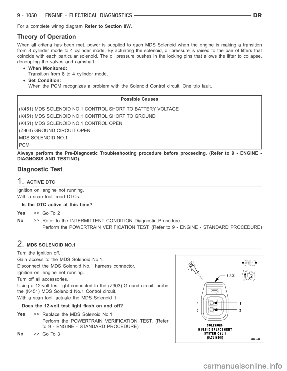
2.MDS SOLENOID NO.1
Turn the ignition off.
Gain access to the MDS Solenoid No.1.
Disconnect the MDS Solenoid No.1 harness connector.
Ignition on, engine not running.
Turn off all accessories.
Using a 12-volt test light connected to the (Z903) Ground circuit, probe
the (K451) MDS Solenoid No.1 Control circuit.
With a scan tool, actuate the MDS Solenoid 1.
Does the 12-volt test light flash on and off?
Ye s>>
Replace the MDS Solenoid No.1.
Perform the POWERTRAIN VERIFICATION TEST. (Refer
to 9 - ENGINE - STANDARD PROCEDURE)
No>>
Go To 3
Page 360 of 5267
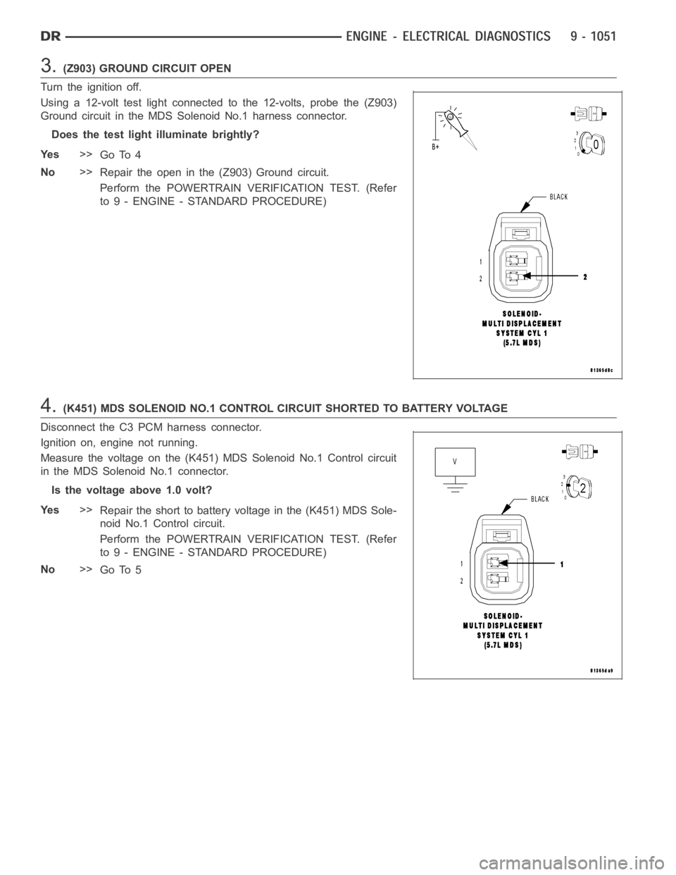
3.(Z903) GROUND CIRCUIT OPEN
Turn the ignition off.
Using a 12-volt test light connected to the 12-volts, probe the (Z903)
Ground circuit in the MDS Solenoid No.1 harness connector.
Does the test light illuminate brightly?
Ye s>>
Go To 4
No>>
Repair the open in the (Z903) Ground circuit.
Perform the POWERTRAIN VERIFICATION TEST. (Refer
to 9 - ENGINE - STANDARD PROCEDURE)
4.(K451) MDS SOLENOID NO.1 CONTROL CIRCUIT SHORTED TO BATTERY VOLTAGE
Disconnect the C3 PCM harness connector.
Ignition on, engine not running.
Measure the voltage on the (K451) MDS Solenoid No.1 Control circuit
in the MDS Solenoid No.1 connector.
Is the voltage above 1.0 volt?
Ye s>>
Repair the short to battery voltage in the (K451) MDS Sole-
noid No.1 Control circuit.
Perform the POWERTRAIN VERIFICATION TEST. (Refer
to 9 - ENGINE - STANDARD PROCEDURE)
No>>
Go To 5
Page 364 of 5267
For a complete wiring diagramRefer to Section 8W.
Theory of Operation
When all criteria has been met, power is supplied to each MDS Solenoid when the engine is making a transition
from 8 cylinder mode to 4 cylinder mode. By actuating the solenoid, oil pressure is raised to the pair of lifters that
coincide with each particular solenoid. The oil pressure pushes in the locking pins that allows the lifter to collapse,
decoupling the valves and camshaft.
When Monitored:
Transition from 8 to 4 cylinder mode.
Set Condition:
The MDS fails to disengage for cylinder 1. One trip fault.
Possible Causes
(K451) MDS SOLENOID NO.1 CONTROL SHORT TO VOLTAGE
OIL PASSAGES RESTRICTED
LIFTER
MDS SOLENOID NO.1
PCM
Always perform the Pre-Diagnostic Troubleshooting procedure before proceeding. (Refer to 9 - ENGINE -
DIAGNOSIS AND TESTING).
Diagnostic Test
1.ACTIVE DTC
Ignition on, engine not running.
With a scan tool, read DTCs.
Is the DTC active at this time?
Ye s>>
Go To 2
No>>
Refer to the INTERMITTENT CONDITION Diagnostic Procedure.
Perform the POWERTRAIN VERIFICATION TEST. (Refer to 9 - ENGINE - STANDARD PROCEDURE)
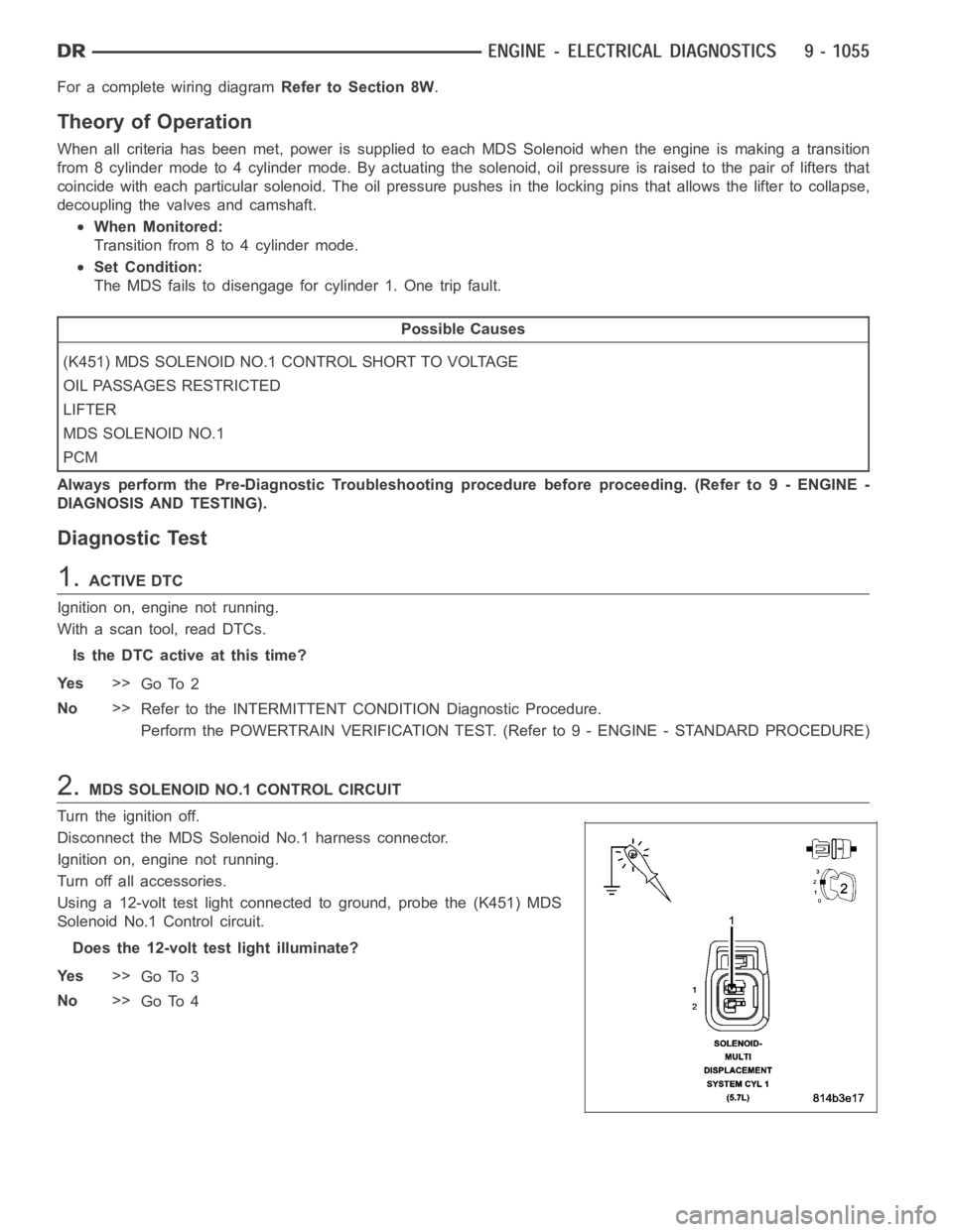
2.MDS SOLENOID NO.1 CONTROL CIRCUIT
Turn the ignition off.
Disconnect the MDS Solenoid No.1 harness connector.
Ignition on, engine not running.
Turn off all accessories.
Using a 12-volt test light connected to ground, probe the (K451) MDS
Solenoid No.1 Control circuit.
Does the 12-volt test light illuminate?
Ye s>>
Go To 3
No>>
Go To 4
Page 368 of 5267
For a complete wiring diagramRefer to Section 8W.
Theory of Operation
When all criteria has been met, power is supplied to each MDS Solenoid when the engine is making a transition
from 8 cylinder mode to 4 cylinder mode. By actuating the solenoid, oil pressure is raised to the pair of lifters that
coincide with each particular solenoid. The oil pressure pushes in the locking pins that allows the lifter to collapse,
decoupling the valves and camshaft.
When Monitored:
Transition from 8 to 4 cylinder mode.
Set Condition:
When the PCM recognizes a problem with the Solenoid Control circuit. One trip fault.
Possible Causes
(K452) MDS SOLENOID NO.4 CONTROL SHORT TO BATTERY VOLTAGE
(K452) MDS SOLENOID NO.4 CONTROL SHORT TO GROUND
(K452) MDS SOLENOID NO.4 CONTROL OPEN
(Z903) GROUND CIRCUIT OPEN
MDS SOLENOID NO.4
PCM
Always perform the Pre-Diagnostic Troubleshooting procedure before proceeding. (Refer to 9 - ENGINE -
DIAGNOSIS AND TESTING).
Diagnostic Test
1.ACTIVE DTC
Ignition on, engine not running.
With a scan tool, read DTCs.
Is the DTC active at this time?
Ye s>>
Go To 2
No>>
Refer to the INTERMITTENT CONDITION Diagnostic Procedure.
Perform the POWERTRAIN VERIFICATION TEST. (Refer to 9 - ENGINE - STANDARD PROCEDURE)
2.MDS SOLENOID NO.4
Turn the ignition off.
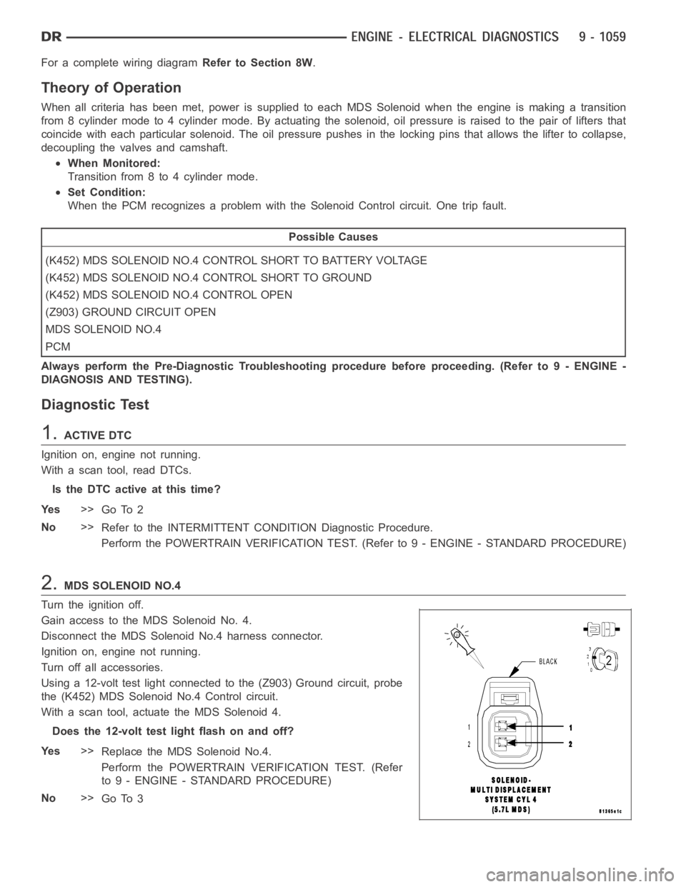
Gain access to the MDS Solenoid No. 4.
Disconnect the MDS Solenoid No.4 harness connector.
Ignition on, engine not running.
Turn off all accessories.
Using a 12-volt test light connected to the (Z903) Ground circuit, probe
the (K452) MDS Solenoid No.4 Control circuit.
With a scan tool, actuate the MDS Solenoid 4.
Does the 12-volt test light flash on and off?
Ye s>>
Replace the MDS Solenoid No.4.
Perform the POWERTRAIN VERIFICATION TEST. (Refer
to 9 - ENGINE - STANDARD PROCEDURE)
No>>
Go To 3
Page 369 of 5267
3.(Z903) GROUND CIRCUIT OPEN
Turn the ignition off.
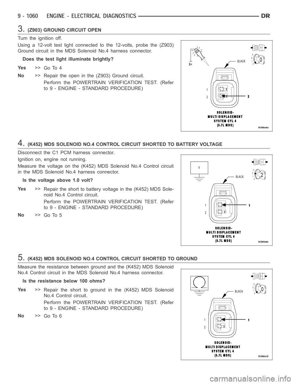
Using a 12-volt test light connected to the 12-volts, probe the (Z903)
Ground circuit in the MDS Solenoid No.4 harness connector.
Does the test light illuminate brightly?
Ye s>>
Go To 4
No>>
Repair the open in the (Z903) Ground circuit.
Perform the POWERTRAIN VERIFICATION TEST. (Refer
to 9 - ENGINE - STANDARD PROCEDURE)
4.(K452) MDS SOLENOID NO.4 CONTROL CIRCUIT SHORTED TO BATTERY VOLTAGE
Disconnect the C1 PCM harness connector.
Ignition on, engine not running.
Measure the voltage on the (K452) MDS Solenoid No.4 Control circuit
in the MDS Solenoid No.4 harness connector.
Is the voltage above 1.0 volt?
Ye s>>
Repair the short to battery voltage in the (K452) MDS Sole-
noid No.4 Control circuit.
Perform the POWERTRAIN VERIFICATION TEST. (Refer
to 9 - ENGINE - STANDARD PROCEDURE)
No>>
Go To 5
5.(K452) MDS SOLENOID NO.4 CONTROL CIRCUIT SHORTED TO GROUND
Measure the resistance between ground and the (K452) MDS Solenoid
No.4 Control circuit in the MDS Solenoid No.4 harness connector.
Istheresistancebelow100ohms?
Ye s>>
Repair the short to ground in the (K452) MDS Solenoid
No.4 Control circuit.
Perform the POWERTRAIN VERIFICATION TEST. (Refer
to 9 - ENGINE - STANDARD PROCEDURE)
No>>
Go To 6