Page 645 of 5267

P0381-WAIT TO START LAMP INOPERATIVE
For a complete wiring diagramRefer to Section 8W.
When Monitored:
Ignition on.
Set Condition:
The cluster sends a signal to the ECM that it has detected a failed wait to start lamp.
Possible Causes
FUSED IGNITION SWITCH OUTPUT CIRCUIT OPEN
WAIT-TO-START LIGHT BULB
WIRING/CONNECTOR PROBLEM
ECM
Always perform the Pre-Diagnostic Troubleshooting procedure before proceeding. (Refer to 9 - ENGINE -
DIAGNOSIS AND TESTING)
Diagnostic Test
1.WAIT-TO-START LAMP DOES NOT COME ON
Turn the ignition off.
While watching the wait-to-start lamp, turn the ignition key on.
Did the wait-to-start lamp light?
Ye s>>
Go To 2
No>>
Go To 3
2.WAIT-TO-START LAMP STAYS ON ALL THE TIME
Turn the ignition off.
While watching the wait-to-start lamp, turn the ignition key on.
Does the wait-to-start lamp stay on all the time?
Ye s>>
Go To 3
No>>
Wait-to-start Lamp operating normally. Test passed.
Perform POWERTRAIN VERIFICATION TEST VER - 1 (DIESEL). (Refer to 8 - ELECTRICAL/ELEC-
TRONIC CONTROL MODULES/ENGINE CONTROL MODULE - DIAGNOSIS AND TESTING)
Page 646 of 5267
3.FUSED IGNITION SWITCH OUTPUT CIRCUIT OPEN
Turn the ignition off.
Remove the cluster.
NOTE: Check connectors - Clean/repair as necessary.
Turn the ignition on.
Using a 12-Volt test Light, check the Fused Ignition Switch Run/Start
circuit.
Is the light illuminated and bright?
Ye s>>
Go To 4
No>>
Repair the open fused Ignition Switch Output circuit.
Perform POWERTRAIN VERIFICATION TEST VER - 1
(DIESEL). (Refer to 8 - ELECTRICAL/ELECTRONIC CON-
TROL MODULES/ENGINE CONTROL MODULE - DIAG-
NOSIS AND TESTING)
4.WAIT-TO-START LIGHT BULB
Remove and inspect the Wait-to-Start Bulb.
Is the Bulb Ok?
Ye s>>
Te s t c o m p l e t e .
No>>
Replace the Wait-to-Start Bulb.
Perform POWERTRAIN VERIFICATION TEST VER - 1 (DIESEL). (Refer to 8 - ELECTRICAL/ELEC-
TRONIC CONTROL MODULES/ENGINE CONTROL MODULE - DIAGNOSIS AND TESTING)
Page 744 of 5267

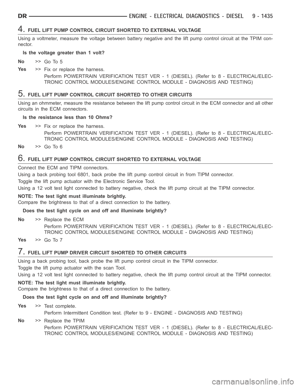
4.FUEL LIFT PUMP CONTROL CIRCUIT SHORTED TO EXTERNAL VOLTAGE
Using a voltmeter, measure the voltage between battery negative and the lift pump control circuit at the TPIM con-
nector.
Is the voltage greater than 1 volt?
No>>
Go To 5
Ye s>>
Fix or replace the harness.
Perform POWERTRAIN VERIFICATION TEST VER - 1 (DIESEL). (Refer to 8 - ELECTRICAL/ELEC-
TRONIC CONTROL MODULES/ENGINE CONTROL MODULE - DIAGNOSIS AND TESTING)
5.FUEL LIFT PUMP CONTROL CIRCUIT SHORTED TO OTHER CIRCUITS
Using an ohmmeter, measure the resistance between the lift pump control circuit in the ECM connector and all other
circuits in the ECM connectors.
Is the resistance less than 10 Ohms?
Ye s>>
Fix or replace the harness.
Perform POWERTRAIN VERIFICATION TEST VER - 1 (DIESEL). (Refer to 8 - ELECTRICAL/ELEC-
TRONIC CONTROL MODULES/ENGINE CONTROL MODULE - DIAGNOSIS AND TESTING)
No>>
Go To 6
6.FUEL LIFT PUMP CONTROL CIRCUIT SHORTED TO EXTERNAL VOLTAGE
Connect the ECM and TIPM connectors.
Using a back probing tool 6801, back probe the lift pump control circuit in from TIPM connector.
Toggle the lift pump actuator with the Electronic Service Tool.
Using a 12 volt test light connected to battery negative, check the lift pump circuit at the TIPM connector.
NOTE: The test light must illuminate brightly.
Compare the brightness to that of a direct connection to the battery.
Does the test light cycle on and off and illuminate brightly?
No>>
Replace the ECM
Perform POWERTRAIN VERIFICATION TEST VER - 1 (DIESEL). (Refer to 8 - ELECTRICAL/ELEC-
TRONIC CONTROL MODULES/ENGINE CONTROL MODULE - DIAGNOSIS AND TESTING)
Ye s>>
Go To 7
7.FUEL LIFT PUMP DRIVER CIRCUIT SHORTED TO OTHER CIRCUITS
Using a back probing tool, back probe the lift pump control circuit in the TIPM connector.
Toggle the lift pump actuator with the scan Tool.
Using a 12 volt test light connected to battery negative, check the lift pump control circuit at the TIPM connector.
NOTE: The test light must illuminate brightly.
Compare the brightness to that of a direct connection to the battery.
Does the test light cycle on and off and illuminate brightly?
Ye s>>
Te s t c o m p l e t e .
Perform Intermittent Condition test. (Refer to 9 - ENGINE - DIAGNOSIS AND TESTING)
No>>
Replace the TPIM
Perform POWERTRAIN VERIFICATION TEST VER - 1 (DIESEL). (Refer to 8 - ELECTRICAL/ELEC-
TRONIC CONTROL MODULES/ENGINE CONTROL MODULE - DIAGNOSIS AND TESTING)
Page 746 of 5267

When Monitored:
Whilethekeyison.
Set Condition:
The commanded signal to the fuel lift pump relay does not match the feedbacksignal from the fuel lift pump
relay.
Possible Causes
DAMAGED WIRING HARNESS
LIFT PUMP DRIVER CIRCUIT SHORTED TO GROUND
ECM
TIPM
Always perform the Pre-Diagnostic Troubleshooting procedure before proceeding. (Refer to 9 - ENGINE -
DIAGNOSIS AND TESTING)
Diagnostic Test
1.LIFT PUMP DRIVER CIRCUIT SHORTED TO GROUND
Turn the ignition on, engine off.
Disconnect the ECM and TIPM connectors.
NOTE: Check connectors - Clean/repair as necessary.
Using an ohmmeter, measure the resistance of the lift pump driver wire between the ECM connector and ground.
Is the resistance less than 10 Ohms?
Ye s>>
Fix or repair the wire harness.
Perform POWERTRAIN VERIFICATION TEST VER - 1 (DIESEL). (Refer to 8 - ELECTRICAL/ELEC-
TRONIC CONTROL MODULES/ENGINE CONTROL MODULE - DIAGNOSIS AND TESTING)
No>>
Go To 2
2.ECM
Turn Ignition off.
Connect the ECM and TIPM connectors.
Turn the ignition on, engine off.
Using a back probing tool 6801, back probe the lift pump logic pin in from TIPM connector.
Toggle the lift pump actuator with the Electronic Service Tool.
Using a 12 volt test light connected to battery negative, check the lift pump circuit at the TIPM connector.
NOTE: The test light must illuminate brightly.
Compare the brightness to that of a direct connection to the battery.
Does the test light cycle on and off and illuminate brightly?
Ye s>>
Go To 3
No>>
Replace the ECM.
Perform POWERTRAIN VERIFICATION TEST VER - 1 (DIESEL). (Refer to 8 - ELECTRICAL/ELEC-
TRONIC CONTROL MODULES/ENGINE CONTROL MODULE - DIAGNOSIS AND TESTING)
Page 747 of 5267
3.TIPM
Using a back probing tool 6801, back probe the lift pump power pin in from TIPM connector.
Toggle the lift pump actuator with the Electronic Service Tool.
Using a 12 volt test light connected to battery negative, check the lift pump circuit at the TIPM connector.
NOTE: The test light must illuminate brightly.
Compare the brightness to that of a direct connection to the battery.
Does the test light cycle on and off and illuminate brightly?
Ye s>>
Te s t c o m p l e t e .
Perform Intermittent Condition test. (Refer to 9 - ENGINE - DIAGNOSIS AND TESTING)
No>>
Replace the TPIM
Perform POWERTRAIN VERIFICATION TEST VER - 1 (DIESEL). (Refer to 8 - ELECTRICAL/ELEC-
TRONIC CONTROL MODULES/ENGINE CONTROL MODULE - DIAGNOSIS AND TESTING)
Page 759 of 5267

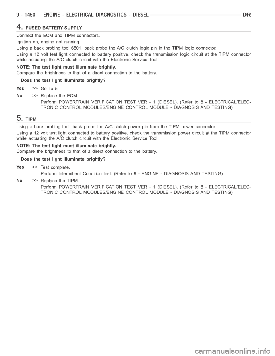
4.FUSED BATTERY SUPPLY
Connect the ECM and TIPM connectors.
Ignition on, engine not running.
Using a back probing tool 6801, back probe the A/C clutch logic pin in the TIPM logic connector.
Usinga12volttestlightconnectedtobatterypositive,checkthetransmission logic circuit at the TIPM connector
while actuating the A/C clutch circuit with the Electronic Service Tool.
NOTE: The test light must illuminate brightly.
Compare the brightness to that of a direct connection to the battery.
Does the test light illuminate brightly?
Ye s>>
Go To 5
No>>
Replace the ECM.
Perform POWERTRAIN VERIFICATION TEST VER - 1 (DIESEL). (Refer to 8 - ELECTRICAL/ELEC-
TRONIC CONTROL MODULES/ENGINE CONTROL MODULE - DIAGNOSIS AND TESTING)
5.TIPM
Using a back probing tool, back probe the A/C clutch power pin from the TIPM power connector.
Using a 12 volt test light connected to battery positive, check the transmission power circuit at the TIPM connector
while actuating the A/C clutch circuit with the Electronic Service Tool.
NOTE: The test light must illuminate brightly.
Compare the brightness to that of a direct connection to the battery.
Does the test light illuminate brightly?
Ye s>>
Te s t c o m p l e t e .
Perform Intermittent Condition test. (Refer to 9 - ENGINE - DIAGNOSIS AND TESTING)
No>>
Replace the TIPM.
Perform POWERTRAIN VERIFICATION TEST VER - 1 (DIESEL). (Refer to 8 - ELECTRICAL/ELEC-
TRONIC CONTROL MODULES/ENGINE CONTROL MODULE - DIAGNOSIS AND TESTING)
Page 761 of 5267

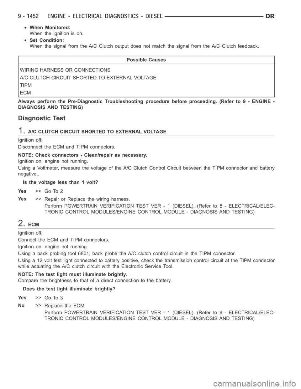
When Monitored:
When the ignition is on.
Set Condition:
When the signal from the A/C Clutch output does not match the signal from theA/C Clutch feedback.
Possible Causes
WIRING HARNESS OR CONNECTIONS
A/C CLUTCH CIRCUIT SHORTED TO EXTERNAL VOLTAGE
TIPM
ECM
Always perform the Pre-Diagnostic Troubleshooting procedure before proceeding. (Refer to 9 - ENGINE -
DIAGNOSIS AND TESTING)
Diagnostic Test
1.A/C CLUTCH CIRCUIT SHORTED TO EXTERNAL VOLTAGE
Ignition off.
Disconnect the ECM and TIPM connectors.
NOTE: Check connectors - Clean/repair as necessary.
Ignition on, engine not running.
Using a Voltmeter, measure the voltage of the A/C Clutch Control Circuit between the TIPM connector and battery
negative..
Is the voltage less than 1 volt?
Ye s>>
Go To 2
Ye s>>
Repair or Replace the wiring harness.
Perform POWERTRAIN VERIFICATION TEST VER - 1 (DIESEL). (Refer to 8 - ELECTRICAL/ELEC-
TRONIC CONTROL MODULES/ENGINE CONTROL MODULE - DIAGNOSIS AND TESTING)
2.ECM
Ignition off.
Connect the ECM and TIPM connectors.
Ignition on, engine not running.
Using a back probing tool 6801, back probe the A/C clutch control circuit inthe TIPM connector.
Using a 12 volt test light connected to battery positive, check the transmission control circuit at the TIPM connector
while actuating the A/C clutch circuit with the Electronic Service Tool.
NOTE: The test light must illuminate brightly.
Compare the brightness to that of a direct connection to the battery.
Does the test light illuminate brightly?
Ye s>>
Go To 3
No>>
Replace the ECM.
Perform POWERTRAIN VERIFICATION TEST VER - 1 (DIESEL). (Refer to 8 - ELECTRICAL/ELEC-
TRONIC CONTROL MODULES/ENGINE CONTROL MODULE - DIAGNOSIS AND TESTING)
Page 762 of 5267
3.TIPM
Using a back probing tool 6801, back probe the A/C clutch power circuit in the TIPM connector.
Using a 12 volt test light connected to battery positive, check the transmission power circuit at the TIPM connector
while actuating the A/C clutch circuit with the Electronic Service Tool.
NOTE: The test light must illuminate brightly.
Compare the brightness to that of a direct connection to the battery.
Does the test light illuminate brightly?
Ye s>>
Te s t c o m p l e t e .
Perform Intermittent Condition test. (Refer to 9 - ENGINE - DIAGNOSIS AND TESTING)
No>>
Replace the TIPM.
Perform POWERTRAIN VERIFICATION TEST VER - 1 (DIESEL). (Refer to 8 - ELECTRICAL/ELEC-
TRONIC CONTROL MODULES/ENGINE CONTROL MODULE - DIAGNOSIS AND TESTING)