2006 DODGE RAM SRT-10 Compression
[x] Cancel search: CompressionPage 2111 of 5267
ROD-PISTON & CONNECTING
DESCRIPTION
The pistons are made of cast aluminum with an added anodized coating on bothsides of the skirt and the top
piston ring groove for reduced wear and it’s low friction properties. Three piston rings are used; two compression
and one three-piece oil control ring. The piston pin (press-fit into the rods) joins the piston to a forged steel, frac-
tured cap, designed connecting rod, with a custom twelve point nine millimeter threaded bolt. The piston and con-
necting rod is serviced as an assembly and is not interchangeable with previous model years.
STANDARD PROCEDURE
PISTON FITTING
All pistons are machined to the same weight in grams,
to maintain piston balance.
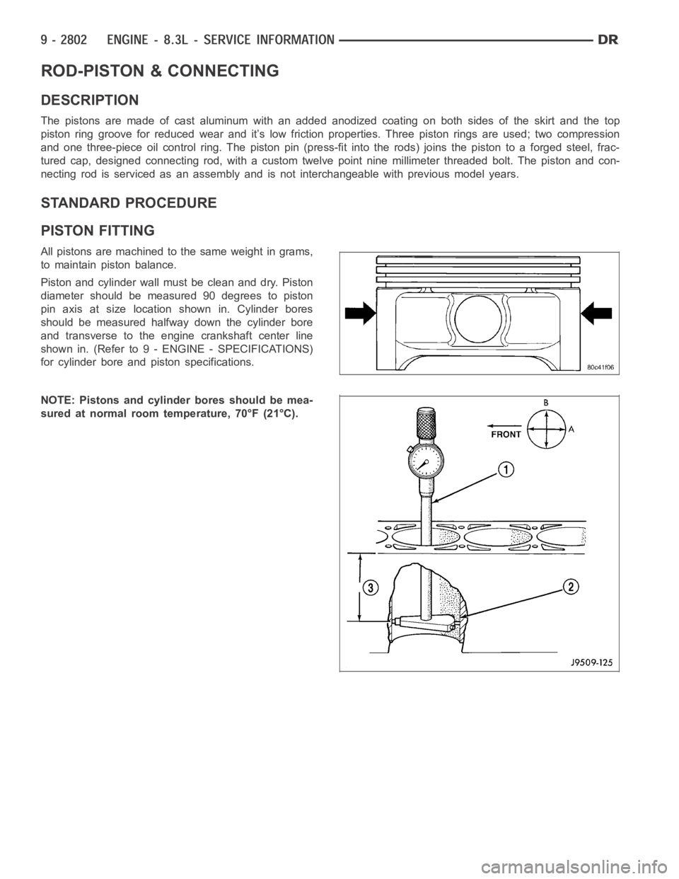
Piston and cylinder wall must be clean and dry. Piston
diameter should be measured 90 degrees to piston
pin axis at size location shown in. Cylinder bores
should be measured halfway down the cylinder bore
and transverse to the engine crankshaft center line
shown in. (Refer to 9 - ENGINE - SPECIFICATIONS)
for cylinder bore and piston specifications.
NOTE: Pistons and cylinder bores should be mea-
sured at normal room temperature, 70°F (21°C).
Page 2162 of 5267
OPERATION
Exhaust gas pressure and energy drive the turbine,
which in turn drives a centrifugal compressor that
compresses the inlet air, and forces the air into the
engine through the charge air cooler and plumbing.
Since heat is a by-product of this compression, the air
must pass through a charge air cooler to cool the
incoming air and maintain power and efficiency.
Increasing air flow to the engine provides:
Improved engine performance
Lower exhaust smoke density
Improved operating economy
Altitude compensation
Noise reduction.
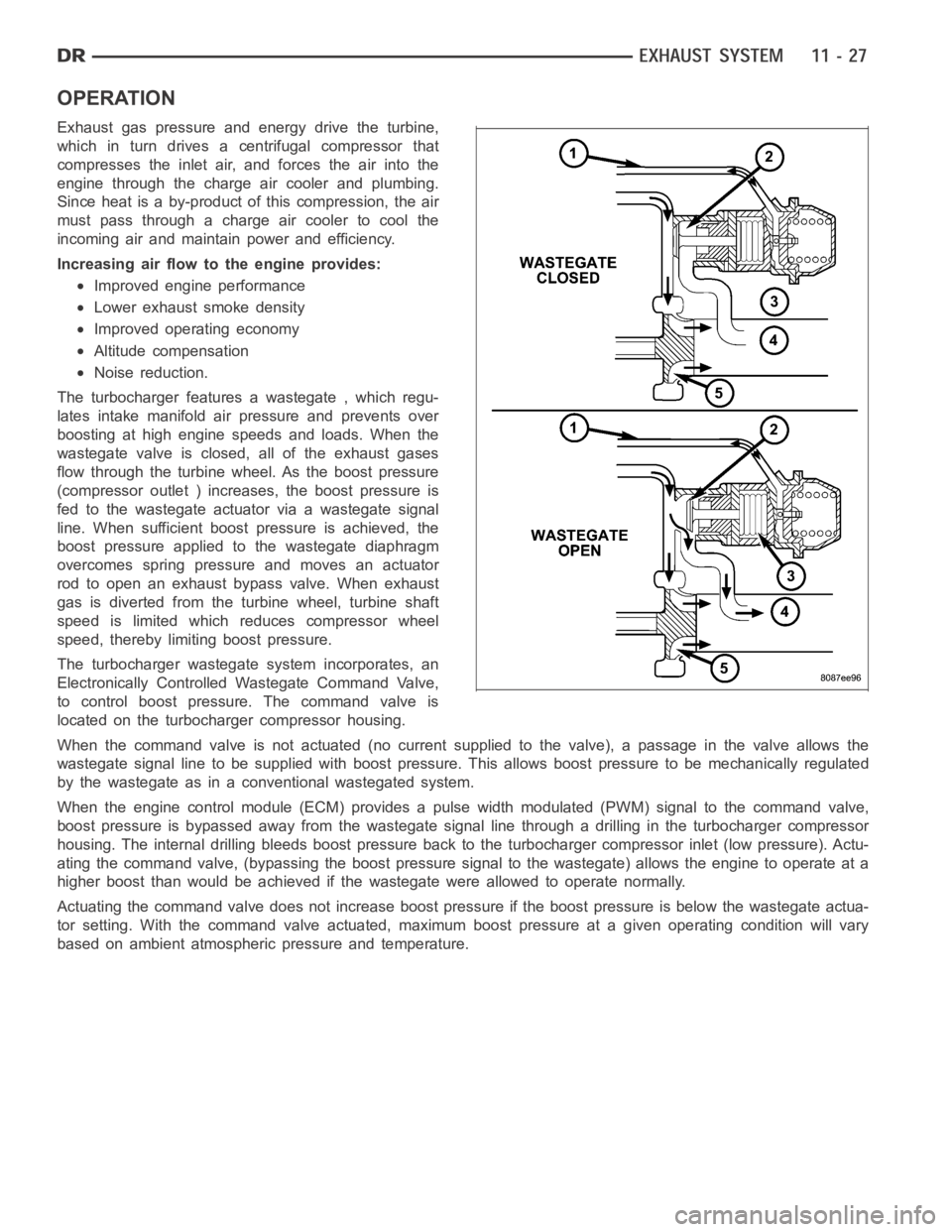
The turbocharger features a wastegate , which regu-
lates intake manifold air pressure and prevents over
boosting at high engine speeds and loads. When the
wastegate valve is closed, all of the exhaust gases
flow through the turbine wheel. As the boost pressure
(compressor outlet ) increases, the boost pressure is
fed to the wastegate actuator via a wastegate signal
line. When sufficient boost pressure is achieved, the
boost pressure applied to the wastegate diaphragm
overcomes spring pressure and moves an actuator
rod to open an exhaust bypass valve. When exhaust
gas is diverted from the turbine wheel, turbine shaft
speed is limited which reduces compressor wheel
speed, thereby limiting boost pressure.
The turbocharger wastegate system incorporates, an
Electronically Controlled Wastegate Command Valve,
to control boost pressure. The command valve is
located on the turbocharger compressor housing.
When the command valve is not actuated (no current supplied to the valve), apassage in the valve allows the
wastegate signal line to be supplied with boost pressure. This allows boost pressure to be mechanically regulated
by the wastegate as in a conventional wastegated system.
When the engine control module (ECM) provides a pulse width modulated (PWM) signal to the command valve,
boost pressure is bypassed away from the wastegate signal line through a drilling in the turbocharger compressor
housing. The internal drilling bleeds boost pressure back to the turbocharger compressor inlet (low pressure). Actu-
ating the command valve, (bypassing the boost pressure signal to the wastegate) allows the engine to operate at a
higher boost than would be achieved if the wastegate were allowed to operate normally.
Actuating the command valve does not increase boost pressure if the boost pressure is below the wastegate actua-
tor setting. With the command valve actuated, maximum boost pressure at a given operating condition will vary
based on ambient atmospheric pressure and temperature.
Page 3923 of 5267
RETAINER-OVERRUNNING CLUTCH CAM/OVERDRIVE PISTON
DESCRIPTION
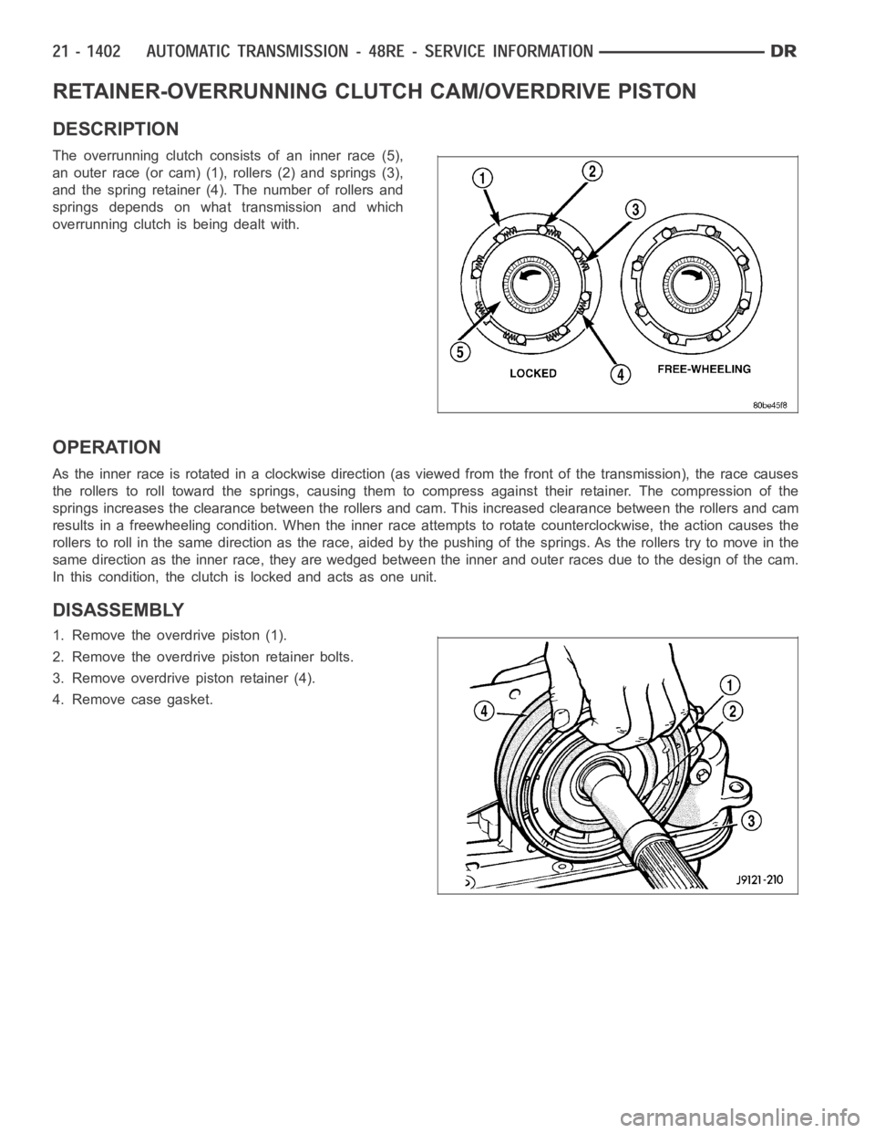
The overrunning clutch consists of an inner race (5),
an outer race (or cam) (1), rollers (2) and springs (3),
and the spring retainer (4). The number of rollers and
springs depends on what transmission and which
overrunning clutch is being dealt with.
OPERATION
Astheinnerraceisrotatedinaclockwisedirection(asviewedfromthefront of the transmission), the race causes
the rollers to roll toward the springs, causing them to compress against their retainer. The compression of the
springs increases the clearance between the rollers and cam. This increased clearance between the rollers and cam
results in a freewheeling condition. When the inner race attempts to rotate counterclockwise, the action causes the
rollers to roll in the same direction as the race, aided by the pushing of thesprings. As the rollers try to move in the
same direction as the inner race, they are wedged between the inner and outer races due to the design of the cam.
In this condition, the clutch is locked and acts as one unit.
DISASSEMBLY
1. Remove the overdrive piston (1).
2. Remove the overdrive piston retainer bolts.
3. Remove overdrive piston retainer (4).
4. Remove case gasket.
Page 4342 of 5267
Many BSR complaints such as loose trim, can be serviced using the MoparParts BSR Noise Reduction Kit. This
kit contains various tapes including foam, flock and anti-squeak used to eliminate noises caused by metal, plastic
and vinyl components. Long life lubricants and greases can also be used on avariety of components. Refer to the
Buzz, Squeak & Rattle Kit table for material contents and usage.
Buzz, Squeak & Rattle Kit
ITEM FEATURES APPLICATIONS SERVICE TEMP
Itch And Squeak
TapeAn abrasion resistant material
thin enough to conform to most
irregular surfaces. Stops most
itches and squeaks.Between metal and metal,
metal and plastic, metal and
vinyl, vinyl and plastic. Interior.
Examples: Trim panels and
bezels.-40° to 225° F
(-40° to 107° C)
Black Nylon Flock Nylon Flock with an aggressive
acrylic adhesive. Provides for
cushioning and compression fit,
also isolates components.
Water-resistant.Between metal and metal,
metal and plastic, vinyl and
plastic.
Examples: Pull cups, bezels,
clips, ducts, top cover to glass,
cowl panel.-40° to 180° F
(-40° to 82° C)
High Density
Urethane FoamTear resistant, highly resilient
and durable.Between metal and metal,
metal and plastic. Water-
resistant.
Examples: I/P, heavy metal
rattles, isolating brackets.-40° to 180° F
(-40° to 82° C)
Open Cell Foam
TapeSoft foam conforms to irregular
surfaces.Wire harness and connector
wrap.
Examples: Seals, gasket,
wiring, heat ducts.-40° to 180° F
(-40° to 82° C)
Closed Cell Low
Density Foam TapeSoft, conformable. Water-
resistant.Wherever bulk is needed.
Prevents closing flutters and
rattles when applied to door
watershield.
Examples: Door, I/P.-40° to 180° F
(-40° to 82° C)
NYE
Grease 880 Long life. Suspensions.
Examples: Strut bushings, sway
bars.-40° to 390° F
(-40° to 200° C)
Krytox
Oil Long life. Will not dry out or
harm plastics or rubber.When access is not possible, oil
will migrate to condition. Vinyl,
rubber, plastic, metal.
Examples: Convertible top
bushings, pull cups trim panel
inserts.-30° to 400° F
(-34° to 205° C)
Krytox
Grease Long life. Will not dry out or
harm plastics or rubber.Vinyl, rubber, plastic, metal,
glass.
Examples: Weather-strips,
backlite and windshield
moldings.-30° to 400° F
(-34° to 205° C)
PLASTIC BODY PANEL REPAIR
There are many different types of plastics used in today’s automotive environment. We group plastics in three dif-
ferent categories: Rigid, Semi-Rigid, and Flexible. Any of these plastics may require the use of an adhesion pro-
moter for repair. These types of plastic are used extensively on DaimlerChrysler Motors vehicles. Always follow
repair material manufacturer’s plastic identification and repair procedures.
Page 4611 of 5267
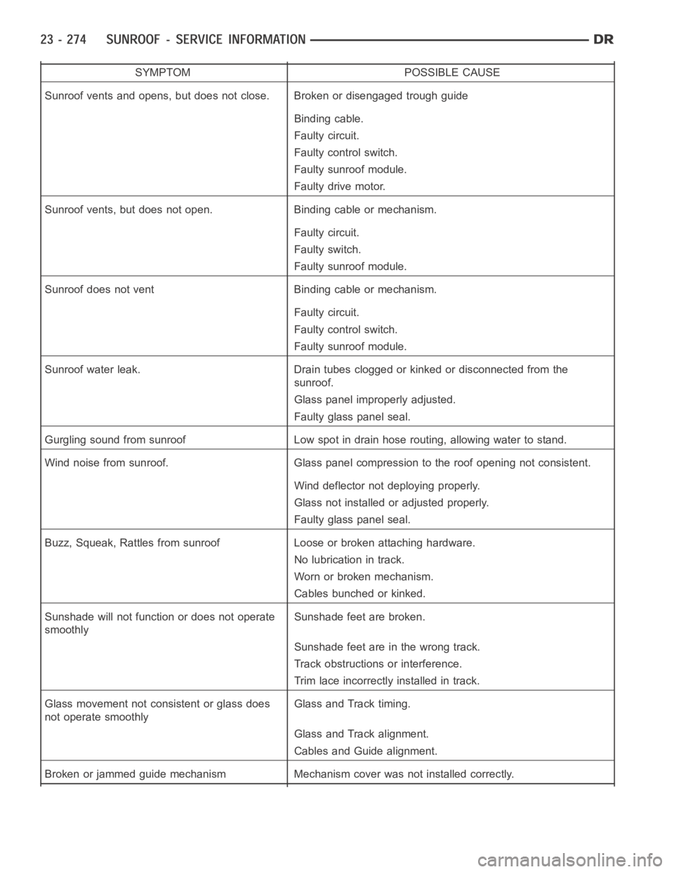
SYMPTOM POSSIBLE CAUSE
Sunroof vents and opens, but does not close. Broken or disengaged trough guide
Binding cable.
Faulty circuit.
Faulty control switch.
Faulty sunroof module.
Faulty drive motor.
Sunroof vents, but does not open. Binding cable or mechanism.
Faulty circuit.
Faulty switch.
Faulty sunroof module.
Sunroof does not vent Binding cable or mechanism.
Faulty circuit.
Faulty control switch.
Faulty sunroof module.
Sunroof water leak. Drain tubes clogged or kinked or disconnected from the
sunroof.
Glass panel improperly adjusted.
Faulty glass panel seal.
Gurgling sound from sunroof Low spot in drain hose routing, allowing waterto stand.
Wind noise from sunroof. Glass panel compression to the roof opening not consistent.
Wind deflector not deploying properly.
Glass not installed or adjusted properly.
Faulty glass panel seal.
Buzz, Squeak, Rattles from sunroof Loose or broken attaching hardware.
No lubrication in track.
Worn or broken mechanism.
Cables bunched or kinked.
Sunshade will not function or does not operate
smoothlySunshade feet are broken.
Sunshadefeetareinthewrongtrack.
Track obstructions or interference.
Trim lace incorrectly installed in track.
Glass movement not consistent or glass does
not operate smoothlyGlass and Track timing.
Glass and Track alignment.
Cables and Guide alignment.
Broken or jammed guide mechanism Mechanism cover was not installed correctly.
Page 5201 of 5267
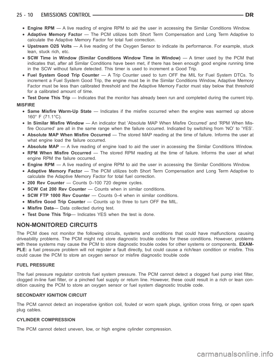
Engine RPM— A live reading of engine RPM to aid the user in accessing the Similar Conditions Window.
Adaptive Memory Factor— The PCM utilizes both Short Term Compensation and Long Term Adaptive to
calculate the Adaptive Memory Factor for total fuel correction.
Upstream O2S Volts— A live reading of the Oxygen Sensor to indicate its performance. For example, stuck
lean, stuck rich, etc.
SCW Time in Window (Similar Conditions Window Time in Window)—Atimer used by the PCM that
indicates that, after all Similar Conditions have been met, if there has been enough good engine running time
in the SCW without failure detected. This timer is used to increment a Good Trip.
Fuel System Good Trip Counter—ATripCounterusedtoturnOFFtheMILforFuelSystemDTCs.To
increment a Fuel System Good Trip, the engine must be in the Similar Conditions Window, Adaptive Memory
Factor must be less than calibrated threshold and the Adaptive Memory Factor must stay below that threshold
for a calibrated amount of time.
Test Done This Trip— Indicates that the monitor has already been run and completed during the current trip.
MISFIRE
Same Misfire Warm-Up State— Indicates if the misfire occurred when the engine was warmed up above
160° F (71.1°C).
In Similar Misfire Window— An indicator that ’Absolute MAP When Misfire Occurred’ and ’RPM When Mis-
fire Occurred’ are all in the same range when the failure occurred. Indicated by switching from ’NO’ to ’YES’.
Absolute MAP When Misfire Occurred— The stored MAP reading at the time of failure. Informs the user at
what engine load the failure occurred.
Absolute MAP— A live reading of engine load to aid the user in accessing the Similar Conditions Window.
RPM When Misfire Occurred— The stored RPM reading at the time of failure. Informs the user at what
engine RPM the failure occurred.
Engine RPM— A live reading of engine RPM to aid the user in accessing the Similar Conditions Window.
Adaptive Memory Factor— The PCM utilizes both Short Term Compensation and Long Term Adaptive to
calculate the Adaptive Memory Factor for total fuel correction.
200 Rev Counter— Counts 0–100 720 degree cycles.
SCW Cat 200 Rev Counter— Counts when in similar conditions.
SCW FTP 1000 Rev Counter— Counts 0–4 when in similar conditions.
Misfire Good Trip Counter— Counts up to three to turn OFF the MIL.
Misfire Data— Data collected during test.
Test Done This Trip— Indicates YES when the test is done.
NON-MONITORED CIRCUITS
The PCM does not monitor the following circuits, systems and conditions that could have malfunctions causing
driveability problems. The PCM might not store diagnostic trouble codes for these conditions. However, problems
with these systems may cause the PCM to store diagnostic trouble codes for other systems or components.EXAM-
PLE:a fuel pressure problem will not register a fault directly, but could causea rich/lean condition or misfire. This
could cause the PCM to store an oxygen sensor or misfire diagnostic troublecode
FUEL PRESSURE
The fuel pressure regulator controls fuel system pressure. The PCM cannotdetect a clogged fuel pump inlet filter,
clogged in-line fuel filter, or a pinched fuel supply or return line. However, these could result in a rich or lean con-
dition causing the PCM to store an oxygen sensor or fuel system diagnostic trouble code.
SECONDARY IGNITION CIRCUIT
The PCM cannot detect an inoperative ignition coil, fouled or worn spark plugs, ignition cross firing, or open spark
plug cables.
CYLINDER COMPRESSION
The PCM cannot detect uneven, low, or high engine cylinder compression.