2006 DODGE RAM SRT-10 Compression
[x] Cancel search: CompressionPage 1759 of 5267
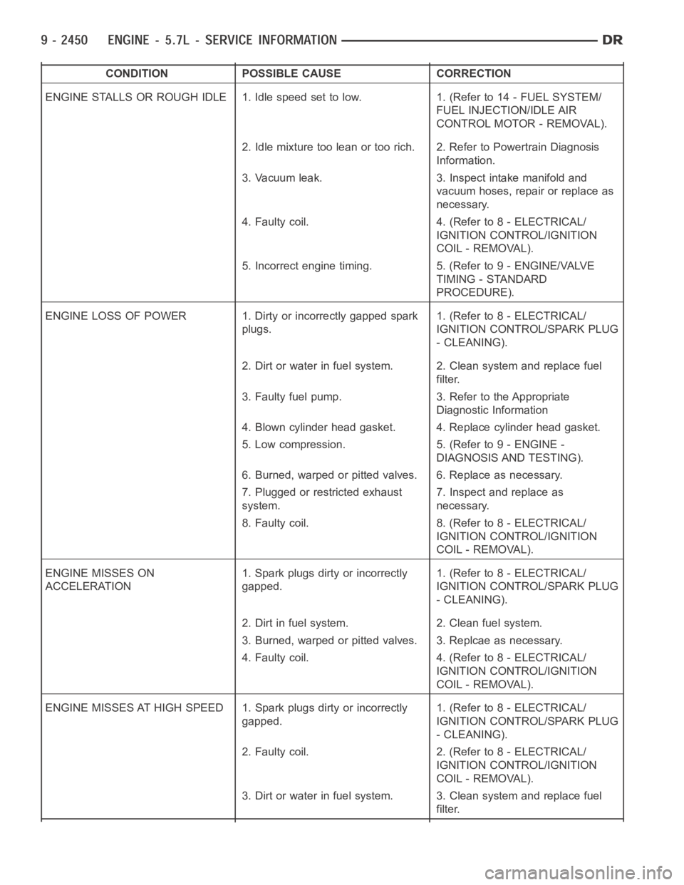
CONDITION POSSIBLE CAUSE CORRECTION
ENGINE STALLS OR ROUGH IDLE 1. Idle speed set to low. 1. (Refer to 14 - FUEL SYSTEM/
FUEL INJECTION/IDLE AIR
CONTROL MOTOR - REMOVAL).
2. Idle mixture too lean or too rich. 2. Refer to Powertrain Diagnosis
Information.
3. Vacuum leak. 3. Inspect intake manifold and
vacuum hoses, repair or replace as
necessary.
4. Faulty coil. 4. (Refer to 8 - ELECTRICAL/
IGNITION CONTROL/IGNITION
COIL - REMOVAL).
5. Incorrect engine timing. 5. (Refer to 9 - ENGINE/VALVE
TIMING - STANDARD
PROCEDURE).
ENGINE LOSS OF POWER 1. Dirty or incorrectly gapped spark
plugs.1. (Refer to 8 - ELECTRICAL/
IGNITION CONTROL/SPARK PLUG
- CLEANING).
2. Dirt or water in fuel system. 2. Clean system and replace fuel
filter.
3. Faulty fuel pump. 3. Refer to the Appropriate
Diagnostic Information
4. Blown cylinder head gasket. 4. Replace cylinder head gasket.
5. Low compression. 5. (Refer to 9 - ENGINE -
DIAGNOSIS AND TESTING).
6. Burned, warped or pitted valves. 6. Replace as necessary.
7. Plugged or restricted exhaust
system.7. Inspect and replace as
necessary.
8. Faulty coil. 8. (Refer to 8 - ELECTRICAL/
IGNITION CONTROL/IGNITION
COIL - REMOVAL).
ENGINE MISSES ON
ACCELERATION1. Spark plugs dirty or incorrectly
gapped.1. (Refer to 8 - ELECTRICAL/
IGNITION CONTROL/SPARK PLUG
- CLEANING).
2. Dirt in fuel system. 2. Clean fuel system.
3. Burned, warped or pitted valves. 3. Replcae as necessary.
4. Faulty coil. 4. (Refer to 8 - ELECTRICAL/
IGNITION CONTROL/IGNITION
COIL - REMOVAL).
ENGINE MISSES AT HIGH SPEED 1. Spark plugs dirty or incorrectly
gapped.1. (Refer to 8 - ELECTRICAL/
IGNITION CONTROL/SPARK PLUG
- CLEANING).
2. Faulty coil. 2. (Refer to 8 - ELECTRICAL/
IGNITION CONTROL/IGNITION
COIL - REMOVAL).
3. Dirt or water in fuel system. 3. Clean system and replace fuel
filter.
Page 1760 of 5267
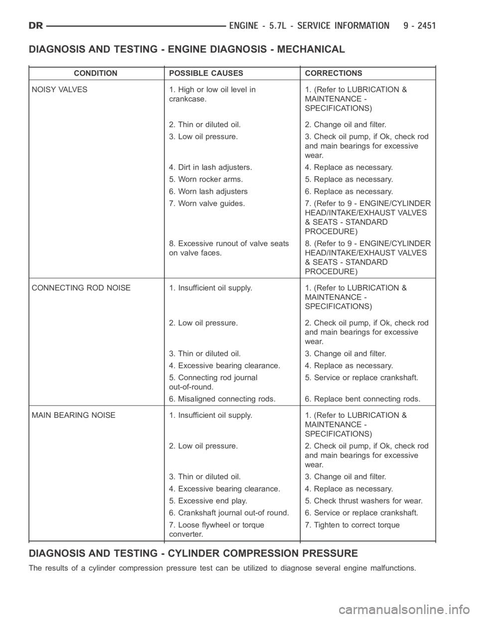
DIAGNOSIS AND TESTING - ENGINE DIAGNOSIS - MECHANICAL
CONDITION POSSIBLE CAUSES CORRECTIONS
NOISY VALVES 1. High or low oil level in
crankcase.1. (Refer to LUBRICATION &
MAINTENANCE -
SPECIFICATIONS)
2. Thin or diluted oil. 2. Change oil and filter.
3. Low oil pressure. 3. Check oil pump, if Ok, check rod
and main bearings for excessive
wear.
4. Dirt in lash adjusters. 4. Replace as necessary.
5. Worn rocker arms. 5. Replace as necessary.
6. Worn lash adjusters 6. Replace as necessary.
7. Worn valve guides. 7. (Refer to 9 - ENGINE/CYLINDER
HEAD/INTAKE/EXHAUST VALVES
& SEATS - STANDARD
PROCEDURE)
8. Excessive runout of valve seats
on valve faces.8. (Refer to 9 - ENGINE/CYLINDER
HEAD/INTAKE/EXHAUST VALVES
& SEATS - STANDARD
PROCEDURE)
CONNECTING ROD NOISE 1. Insufficient oil supply. 1. (Refer to LUBRICATION&
MAINTENANCE -
SPECIFICATIONS)
2. Low oil pressure. 2. Check oil pump, if Ok, check rod
and main bearings for excessive
wear.
3. Thin or diluted oil. 3. Change oil and filter.
4. Excessive bearing clearance. 4. Replace as necessary.
5. Connecting rod journal
out-of-round.5. Service or replace crankshaft.
6. Misaligned connecting rods. 6. Replace bent connecting rods.
MAIN BEARING NOISE 1. Insufficient oil supply. 1. (Refer to LUBRICATION &
MAINTENANCE -
SPECIFICATIONS)
2. Low oil pressure. 2. Check oil pump, if Ok, check rod
and main bearings for excessive
wear.
3. Thin or diluted oil. 3. Change oil and filter.
4. Excessive bearing clearance. 4. Replace as necessary.
5. Excessive end play. 5. Check thrust washers for wear.
6. Crankshaft journal out-of round. 6. Service or replace crankshaft.
7. Loose flywheel or torque
converter.7. Tighten to correct torque
DIAGNOSIS AND TESTING - CYLINDER COMPRESSION PRESSURE
The results of a cylinder compressionpressure test can be utilized to diagnose several engine malfunctions.
Page 1761 of 5267
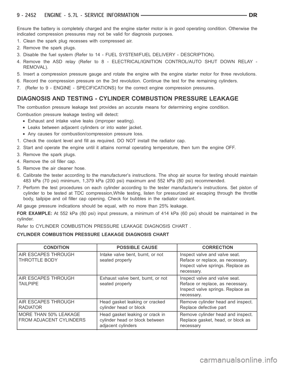
Ensurethebatteryiscompletelychargedandtheenginestartermotorisingood operating condition. Otherwise the
indicated compression pressures may not be valid for diagnosis purposes.
1. Clean the spark plug recesses with compressed air.
2. Remove the spark plugs.
3. Disable the fuel system (Refer to 14 - FUEL SYSTEM/FUEL DELIVERY - DESCRIPTION).
4. Remove the ASD relay (Refer to 8 - ELECTRICAL/IGNITION CONTROL/AUTO SHUTDOWNRELAY-
REMOVAL).
5. Insert a compression pressure gauge and rotate the engine with the engine starter motor for three revolutions.
6. Record the compression pressure on the 3rd revolution. Continue the test for the remaining cylinders.
7. (Refer to 9 - ENGINE - SPECIFICATIONS) for the correct engine compression pressures.
DIAGNOSIS AND TESTING - CYLINDERCOMBUSTION PRESSURE LEAKAGE
The combustion pressure leakage test provides an accurate means for determining engine condition.
Combustion pressure leakage testing will detect:
Exhaust and intake valve leaks (improper seating).
Leaks between adjacent cylinders or into water jacket.
Any causes for combustion/compression pressure loss.
1. Check the coolant level and fill as required. DO NOT install the radiatorcap.
2. Start and operate the engine until it attains normal operating temperature, then turn the engine OFF.
3. Remove the spark plugs.
4. Remove the oil filler cap.
5. Remove the air cleaner hose.
6. Calibrate the tester according to the manufacturer’s instructions. The shop air source for testing should maintain
483 kPa (70 psi) minimum, 1,379 kPa (200 psi) maximum and 552 kPa (80 psi) recommended.
7. Perform the test procedures on each cylinder according to the tester manufacturer’s instructions. Set piston of
cylinder to be tested at TDC compression,While testing, listen for pressurized air escaping through the throttle
body, tailpipe and oil filler cap opening. Check for bubbles in the radiator coolant.
All gauge pressure indications should be equal, with no more than 25% leakage.
FOR EXAMPLE:At 552 kPa (80 psi) input pressure, a minimum of 414 kPa (60 psi) should be maintained in the
cylinder.
Refer to CYLINDER COMBUSTION PRESSURE LEAKAGE DIAGNOSIS CHART .
CYLINDER COMBUSTION PRESSURE LEAKAGE DIAGNOSIS CHART
CONDITION POSSIBLE CAUSE CORRECTION
AIR ESCAPES THROUGH
THROTTLE BODYIntake valve bent, burnt, or not
seated properlyInspect valve and valve seat.
Reface or replace, as necessary.
Inspect valve springs. Replace as
necessary.
AIR ESCAPES THROUGH
TAILPIPEExhaust valve bent, burnt, or not
seated properlyInspect valve and valve seat.
Reface or replace, as necessary.
Inspect valve springs. Replace as
necessary.
AIR ESCAPES THROUGH
RADIATORHead gasket leaking or cracked
cylinder head or blockRemove cylinder head and inspect.
Replace defective part
MORE THAN 50% LEAKAGE
FROM ADJACENT CYLINDERSHead gasket leaking or crack in
cylinder head or block between
adjacent cylindersRemove cylinder head and inspect.
Replace gasket, head, or block as
necessary
Page 1776 of 5267
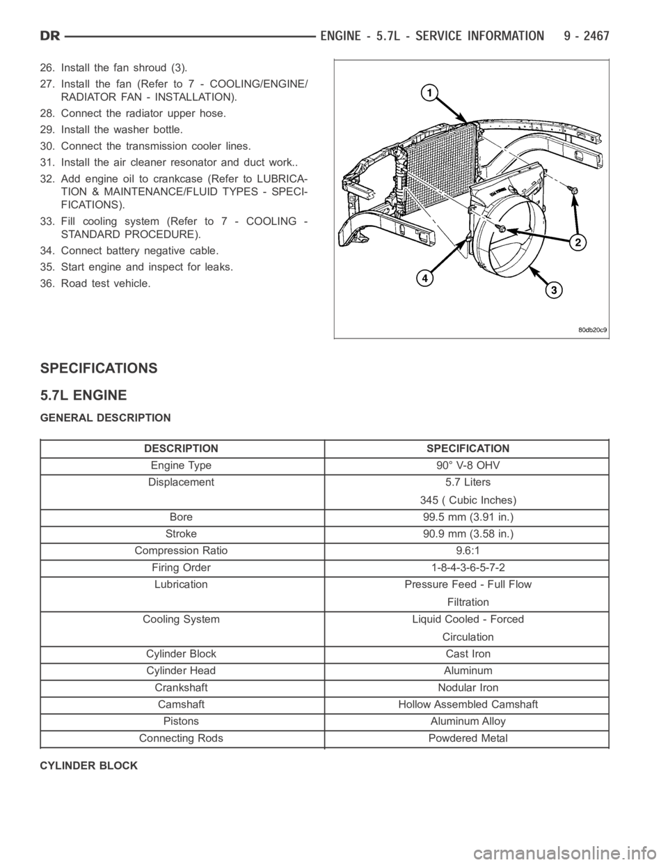
26. Install the fan shroud (3).
27. Install the fan (Refer to 7 - COOLING/ENGINE/
RADIATOR FAN - INSTALLATION).
28. Connect the radiator upper hose.
29. Install the washer bottle.
30. Connect the transmission cooler lines.
31. Install the air cleaner resonator and duct work..
32. Add engine oil to crankcase (Refer to LUBRICA-
TION & MAINTENANCE/FLUID TYPES - SPECI-
FICATIONS).
33. Fill cooling system (Refer to 7 - COOLING -
STANDARD PROCEDURE).
34. Connect battery negative cable.
35. Start engine and inspect for leaks.
36. Road test vehicle.
SPECIFICATIONS
5.7L ENGINE
GENERAL DESCRIPTION
DESCRIPTION SPECIFICATION
Engine Type 90° V-8 OHV
Displacement 5.7 Liters
345 ( Cubic Inches)
Bore 99.5 mm (3.91 in.)
Stroke 90.9 mm (3.58 in.)
Compression Ratio 9.6:1
Firing Order 1-8-4-3-6-5-7-2
Lubrication Pressure Feed - Full Flow
Filtration
Cooling System Liquid Cooled - Forced
Circulation
Cylinder Block Cast Iron
Cylinder Head Aluminum
Crankshaft Nodular Iron
Camshaft Hollow Assembled Camshaft
Pistons Aluminum Alloy
Connecting Rods Powdered Metal
CYLINDER BLOCK
Page 1777 of 5267
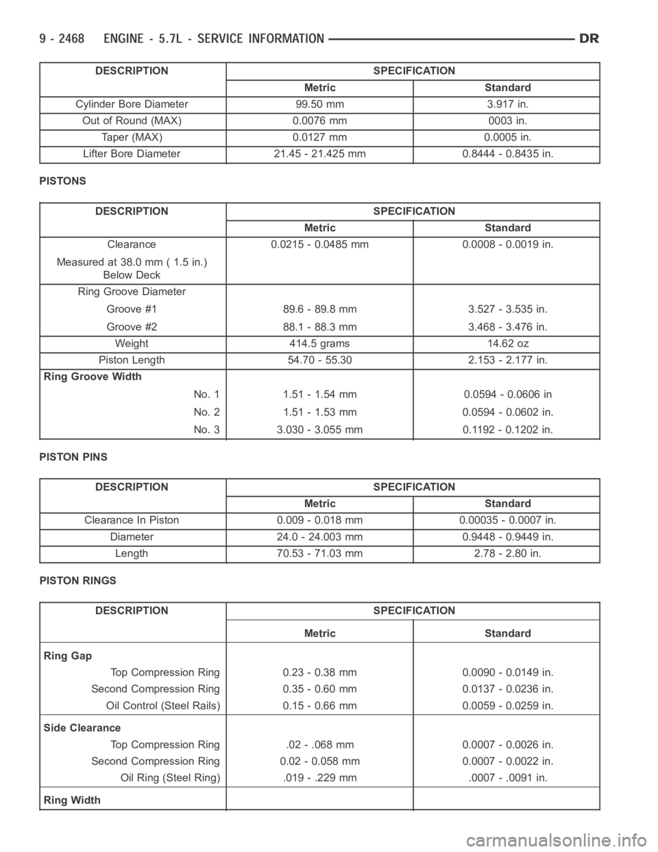
DESCRIPTION SPECIFICATION
Metric Standard
Cylinder Bore Diameter 99.50 mm 3.917 in.
Out of Round (MAX) 0.0076 mm 0003 in.
Taper (MAX) 0.0127 mm 0.0005 in.
Lifter Bore Diameter 21.45 - 21.425 mm 0.8444 - 0.8435 in.
PISTONS
DESCRIPTION SPECIFICATION
Metric Standard
Clearance 0.0215 - 0.0485 mm 0.0008 - 0.0019 in.
Measured at 38.0 mm ( 1.5 in.)
Below Deck
Ring Groove Diameter
Groove #1 89.6 - 89.8 mm 3.527 - 3.535 in.
Groove #2 88.1 - 88.3 mm 3.468 - 3.476 in.
Weight 414.5 grams 14.62 oz
Piston Length 54.70 - 55.30 2.153 - 2.177 in.
Ring Groove Width
No. 1 1.51 - 1.54 mm 0.0594 - 0.0606 in
No. 2 1.51 - 1.53 mm 0.0594 - 0.0602 in.
No. 3 3.030 - 3.055 mm 0.1192 - 0.1202 in.
PISTON PINS
DESCRIPTION SPECIFICATION
Metric Standard
Clearance In Piston 0.009 - 0.018 mm 0.00035 - 0.0007 in.
Diameter 24.0 - 24.003 mm 0.9448 - 0.9449 in.
Length 70.53 - 71.03 mm 2.78 - 2.80 in.
PISTON RINGS
DESCRIPTION SPECIFICATION
Metric Standard
Ring Gap
Top Compression Ring 0.23 - 0.38 mm 0.0090 - 0.0149 in.
Second Compression Ring 0.35 - 0.60 mm 0.0137 - 0.0236 in.
Oil Control (Steel Rails) 0.15 - 0.66 mm 0.0059 - 0.0259 in.
Side Clearance
Top Compression Ring .02 - .068 mm 0.0007 - 0.0026 in.
Second Compression Ring 0.02 - 0.058 mm 0.0007 - 0.0022 in.
Oil Ring (Steel Ring) .019 - .229 mm .0007 - .0091 in.
Ring Width
Page 1778 of 5267
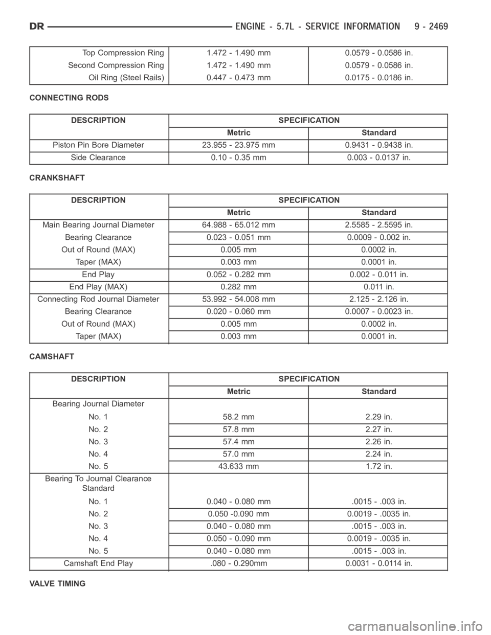
Top Compression Ring 1.472 - 1.490 mm 0.0579 - 0.0586 in.
Second Compression Ring 1.472 - 1.490 mm 0.0579 - 0.0586 in.
Oil Ring (Steel Rails) 0.447 - 0.473 mm 0.0175 - 0.0186 in.
CONNECTING RODS
DESCRIPTION SPECIFICATION
Metric Standard
Piston Pin Bore Diameter 23.955 - 23.975 mm 0.9431 - 0.9438 in.
Side Clearance 0.10 - 0.35 mm 0.003 - 0.0137 in.
CRANKSHAFT
DESCRIPTION SPECIFICATION
Metric Standard
Main Bearing Journal Diameter 64.988 - 65.012 mm 2.5585 - 2.5595 in.
Bearing Clearance 0.023 - 0.051 mm 0.0009 - 0.002 in.
Out of Round (MAX) 0.005 mm 0.0002 in.
Taper (MAX) 0.003 mm 0.0001 in.
End Play 0.052 - 0.282 mm 0.002 - 0.011 in.
End Play (MAX) 0.282 mm 0.011 in.
Connecting Rod Journal Diameter 53.992 - 54.008 mm 2.125 - 2.126 in.
Bearing Clearance 0.020 - 0.060 mm 0.0007 - 0.0023 in.
Out of Round (MAX) 0.005 mm 0.0002 in.
Taper (MAX) 0.003 mm 0.0001 in.
CAMSHAFT
DESCRIPTION SPECIFICATION
Metric Standard
Bearing Journal Diameter
No. 1 58.2 mm 2.29 in.
No. 2 57.8 mm 2.27 in.
No. 3 57.4 mm 2.26 in.
No. 4 57.0 mm 2.24 in.
No. 5 43.633 mm 1.72 in.
Bearing To Journal Clearance
Standard
No. 1 0.040 - 0.080 mm .0015 - .003 in.
No. 2 0.050 -0.090 mm 0.0019 - .0035 in.
No. 3 0.040 - 0.080 mm .0015 - .003 in.
No. 4 0.050 - 0.090 mm 0.0019 - .0035 in.
No. 5 0.040 - 0.080 mm .0015 - .003 in.
Camshaft End Play .080 - 0.290mm 0.0031 - 0.0114 in.
VALVE TIMING
Page 1790 of 5267
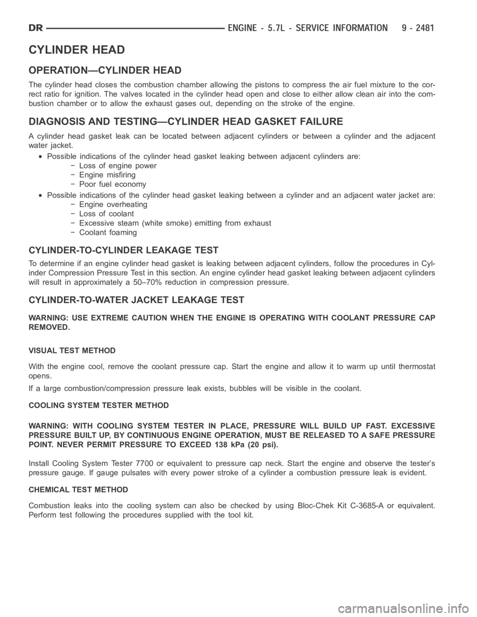
CYLINDER HEAD
OPERATION—CYLINDER HEAD
The cylinder head closes the combustion chamber allowing the pistons to compress the air fuel mixture to the cor-
rect ratio for ignition. The valves located in the cylinder head open and close to either allow clean air into the com-
bustion chamber or to allow the exhaust gases out, depending on the stroke of the engine.
DIAGNOSIS AND TESTING—CYLINDER HEAD GASKET FAILURE
A cylinder head gasket leak can be located between adjacent cylinders or between a cylinder and the adjacent
water jacket.
Possible indications of the cylinder head gasket leaking between adjacent cylinders are:
− Loss of engine power
− Engine misfiring
− Poor fuel economy
Possible indications of the cylinder head gasket leaking between a cylinder and an adjacent water jacket are:
− Engine overheating
− Loss of coolant
− Excessive steam (white smoke) emitting from exhaust
− Coolant foaming
CYLINDER-TO-CYLINDER LEAKAGE TEST
To determine if an engine cylinder head gasket is leaking between adjacentcylinders, follow the procedures in Cyl-
inder Compression Pressure Test in this section. An engine cylinder head gasket leaking between adjacent cylinders
will result in approximately a 50–70% reduction in compression pressure.
CYLINDER-TO-WATER JACKET LEAKAGE TEST
WARNING: USE EXTREME CAUTION WHEN THE ENGINE IS OPERATING WITH COOLANT PRESSURE CAP
REMOVED.
VISUAL TEST METHOD
With the engine cool, remove the coolant pressure cap. Start the engine andallow it to warm up until thermostat
opens.
If a large combustion/compression pressure leak exists, bubbles will be visible in the coolant.
COOLING SYSTEM TESTER METHOD
WARNING: WITH COOLING SYSTEM TESTER IN PLACE, PRESSURE WILL BUILD UP FAST.EXCESSIVE
PRESSURE BUILT UP, BY CONTINUOUS ENGINE OPERATION, MUST BE RELEASED TO A SAFE PRESSURE
POINT. NEVER PERMIT PRESSURE TO EXCEED 138 kPa (20 psi).
Install Cooling System Tester 7700 or equivalent to pressure cap neck. Start the engine and observe the tester’s
pressure gauge. If gauge pulsates with every power stroke of a cylinder a combustion pressure leak is evident.
CHEMICAL TEST METHOD
Combustion leaks into the cooling system can also be checked by using Bloc-Chek Kit C-3685-A or equivalent.
Perform test following the procedures supplied with the tool kit.
Page 1903 of 5267
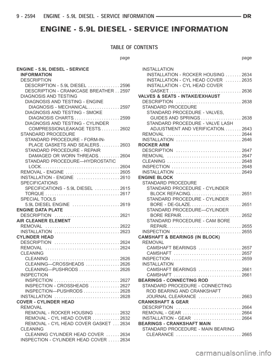
page page
ENGINE - 5.9L DIESEL - SERVICE
INFORMATION
DESCRIPTION
DESCRIPTION - 5.9L DIESEL .............. 2596
DESCRIPTION - CRANKCASE BREATHER . . 2597
DIAGNOSIS AND TESTING
DIAGNOSIS AND TESTING - ENGINE
DIAGNOSIS - MECHANICAL............... 2597
DIAGNOSIS AND TESTING - SMOKE
DIAGNOSIS CHARTS..................... 2599
DIAGNOSIS AND TESTING - CYLINDER
COMPRESSION/LEAKAGE TESTS......... 2602
STANDARD PROCEDURE
STANDARD PROCEDURE - FORM-IN-
PLACE GASKETS AND SEALERS.......... 2603
STANDARD PROCEDURE - REPAIR
DAMAGED OR WORN THREADS.......... 2604
STANDARD PROCEDURE—HYDROSTATIC
LOCK.................................... 2604
REMOVAL - ENGINE ........................ 2605
INSTALLATION - ENGINE ................... 2610
SPECIFICATIONS
SPECIFICATIONS - 5.9L DIESEL ........... 2615
TORQUE ................................. 2617
SPECIAL TOOLS
5.9L DIESEL ENGINE ..................... 2619
ENGINE DATA PLATE
DESCRIPTION ............................. 2621
AIR CLEANER ELEMENT
REMOVAL ................................. 2622
INSTALLATION ............................. 2623
CYLINDER HEAD
DESCRIPTION ............................. 2624
REMOVAL ................................. 2624
CLEANING
CLEANING ............................... 2626
CLEANING—CROSSHEADS ............... 2626
CLEANING—PUSHRODS .................. 2626
INSPECTION
INSPECTION............................. 2627
INSPECTION - CROSSHEADS . . ........... 2627
INSPECTION—PUSHRODS................ 2628
INSTALLATION ............................. 2628
COVER - CYLINDER HEAD
REMOVAL
REMOVAL - ROCKER HOUSING ........... 2632
REMOVAL - CYL HEAD COVER ............ 2632
REMOVAL - CYL HEAD COVER GASKET . . . 2634
CLEANING
CLEANING CYLINDER HEAD COVER ...... 2634
INSPECTION - CYLINDER HEAD COVER ..... 2634INSTALLATION
INSTALLATION - ROCKER HOUSING ....... 2634
INSTALLATION - CYL HEAD COVER ....... 2635
INSTALLATION - CYL HEAD COVER
GASKET................................. 2636
VALVES & SEATS - INTAKE/EXHAUST
DESCRIPTION ............................. 2638
STANDARD PROCEDURE
STANDARD PROCEDURE - VALVES,
GUIDES AND SPRINGS................... 2638
STANDARD PROCEDURE - VALVE LASH
ADJUSTMENT AND VERIFICATION......... 2643
REMOVAL ................................. 2644
INSTALLATION ............................. 2646
ROCKER ARM
DESCRIPTION ............................. 2647
REMOVAL ................................. 2647
CLEANING ................................. 2648
INSPECTION............................... 2648
INSTALLATION ............................. 2649
ENGINE BLOCK
STANDARD PROCEDURE
STANDARD PROCEDURE - CYLINDER
BLOCK REFACING........................ 2651
STANDARD PROCEDURE - CYLINDER
BORE - DE-GLAZE........................ 2651
STANDARD PROCEDURE—CYLINDER
BORE REPAIR............................ 2652
STANDARD PROCEDURE - CAM BORE
REPAIR.................................. 2655
INSPECTION............................... 2655
CAMSHAFT & BEARINGS (IN BLOCK)
REMOVAL
CAMSHAFT BEARINGS................... 2657
CAMSHAFT .............................. 2657
INSPECTION
............................... 2659
INSTALLATION
CAMSHAFT BEARINGS................... 2661
CAMSHAFT .............................. 2661
BEARINGS - CONNECTING ROD
STANDARD PROCEDURE - CONNECTING
ROD BEARING AND CRANKSHAFT
JOURNAL CLEARANCE................... 2663
CRANKSHAFT & GEAR
DESCRIPTION ............................. 2664
REMOVAL - GEAR .......................... 2664
INSTALLATION - GEAR ..................... 2664
BEARINGS - CRANKSHAFT MAIN
STANDARD PROCEDURE - MAIN BEARING
CLEARANCE ............................. 2665