2006 DODGE RAM SRT-10 Compression
[x] Cancel search: CompressionPage 2020 of 5267
page page
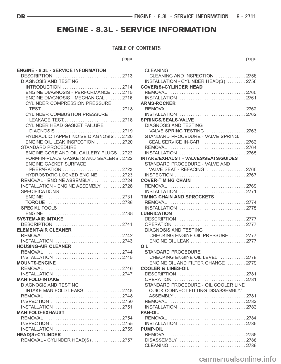
ENGINE - 8.3L - SERVICE INFORMATION
DESCRIPTION ............................. 2713
DIAGNOSIS AND TESTING
INTRODUCTION . ......................... 2714
ENGINE DIAGNOSIS - PERFORMANCE .... 2715
ENGINE DIAGNOSIS - MECHANICAL ....... 2716
CYLINDER COMPRESSION PRESSURE
TEST.................................... 2718
CYLINDER COMBUSTION PRESSURE
LEAKAGE TEST.......................... 2718
CYLINDER HEAD GASKET FAILURE
DIAGNOSIS.............................. 2719
HYDRAULIC TAPPET NOISE DIAGNOSIS . . . 2720
ENGINE OIL LEAK INSPECTION ........... 2720
STANDARD PROCEDURE
ENGINE CORE AND OIL GALLERY PLUGS . 2722
FORM-IN-PLACE GASKETS AND SEALERS . 2722
ENGINE GASKET SURFACE
PREPARATION........................... 2723
HYDROSTATIC LOCKED ENGINE .......... 2723
REMOVAL - ENGINE ASSEMBLY . . ........... 2724
INSTALLATION - ENGINE ASSEMBLY ........ 2728
SPECIFICATIONS
ENGINE ................................. 2731
TORQUE ................................. 2736
SPECIAL TOOLS
ENGINE ................................. 2738
SYSTEM-AIR INTAKE
DESCRIPTION ............................. 2741
ELEMENT-AIR CLEANER
REMOVAL ................................. 2742
INSTALLATION ............................. 2743
HOUSING-AIR CLEANER
REMOVAL ................................. 2744
INSTALLATION ............................. 2745
MOUNTS-ENGINE
REMOVAL ................................. 2746
INSTALLATION ............................. 2747
MANIFOLD-INTAKE
DIAGNOSIS AND TESTING
INTAKE MANIFOLD LEAKS ................ 2748
REMOVAL ................................. 2748
INSPECTION ............................... 2750
INSTALLATION ............................. 2751
MANIFOLD-EXHAUST
REMOVAL ................................. 2754
INSPECTION ............................... 2755
INSTALLATION ............................. 2755
HEAD(S)-CYLINDER
REMOVAL - CYLINDER HEAD(S) ............. 2757CLEANING
CLEANING AND INSPECTION............. 2758
INSTALLATION - CYLINDER HEAD(S) ........ 2758
COVER(S)-CYLINDER HEAD
REMOVAL ................................. 2760
INSTALLATION ............................. 2761
ARMS-ROCKER
REMOVAL ................................. 2762
INSTALLATION ............................. 2762
SPRINGS/SEALS-VALVE
DIAGNOSIS AND TESTING
VALVE SPRING TESTING ................. 2763
STANDARD PROCEDURE - VALVE SPRING/
SEAL SERVICE IN-CAR ................... 2763
REMOVAL ................................. 2764
INSTALLATION ............................. 2765
INTAKE/EXHAUST - VALVES/SEATS/GUIDES
STANDARD PROCEDURE - VALVE AND
VALVE SEAT - REFACING ................. 2766
INSPECTION............................... 2767
COVER-TIMING CHAIN
REMOVAL ................................. 2769
INSTALLATION ............................. 2771
TIMING CHAIN AND SPROCKETS
REMOVAL ................................. 2774
INSTALLATION ............................. 2775
LUBRICATION
DESCRIPTION ............................. 2777
OPERATION ............................... 2777
DIAGNOSIS AND TESTING
CHECKING ENGINE OIL PRESSURE ....... 2777
ENGINE OIL LEAK ........................ 2777
OIL
STANDARD PROCEDURE
CHECKING ENGINE OIL LEVEL........... 2779
ENGINE OILAND FILTER CHANGE ........ 2779
COOLER & LINES-OIL
DESCRIPTION ............................. 2781
OPERATION ............................... 2781
STANDARD PROCEDURE - OIL COOLER LINE
QUICK CONNECT FITTING DISASSEMBLY/
ASSEMBLY............................... 2781
REMOVAL ................................. 2782
INSTALLATION ............................. 2783
PAN-OIL
REMOVAL ................................. 2784
INSTALLATION ............................. 2785
PUMP-OIL
REMOVAL ................................. 2788
DISASSEMBLY . ............................ 2788
CLEANING ................................. 2789
Page 2023 of 5267
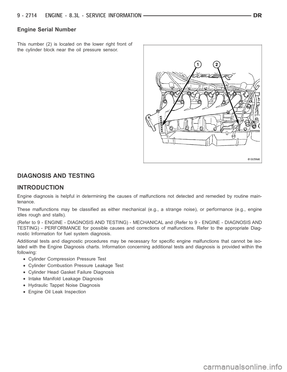
Engine Serial Number
This number (2) is located on the lower right front of
the cylinder block near the oil pressure sensor.
DIAGNOSIS AND TESTING
INTRODUCTION
Engine diagnosis is helpful in determining the causes of malfunctions notdetected and remedied by routine main-
tenance.
These malfunctions may be classified as either mechanical (e.g., a strange noise), or performance (e.g., engine
idles rough and stalls).
(Refer to 9 - ENGINE - DIAGNOSIS AND TESTING) - MECHANICAL and (Refer to 9 - ENGINE - DIAGNOSIS AND
TESTING) - PERFORMANCE for possible causes and corrections of malfunctions. Refer to the appropriate Diag-
nostic Information for fuel system diagnosis.
Additional tests and diagnostic procedures may be necessary for specificengine malfunctions that cannot be iso-
lated with the Engine Diagnosis charts. Information concerning additional tests and diagnosis is provided within the
following:
Cylinder Compression Pressure Test
Cylinder Combustion Pressure Leakage Test
Cylinder Head Gasket Failure Diagnosis
Intake Manifold Leakage Diagnosis
Hydraulic Tappet Noise Diagnosis
Engine Oil Leak Inspection
Page 2024 of 5267
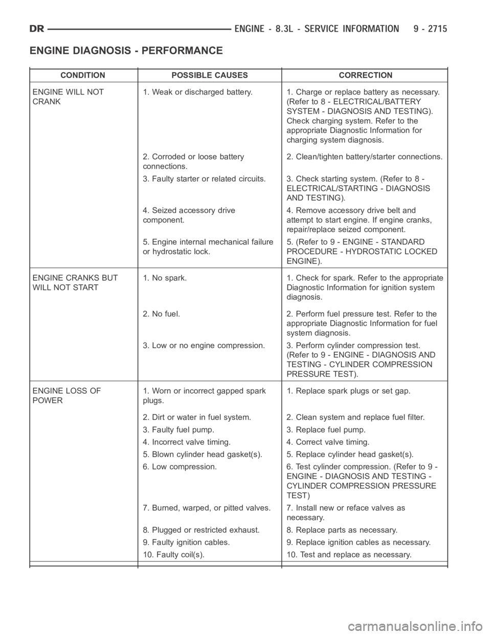
ENGINE DIAGNOSIS - PERFORMANCE
CONDITION POSSIBLE CAUSES CORRECTION
ENGINE WILL NOT
CRANK1. Weak or discharged battery. 1. Charge or replace battery as necessary.
(Refer to 8 - ELECTRICAL/BATTERY
SYSTEM - DIAGNOSIS AND TESTING).
Check charging system. Refer to the
appropriate Diagnostic Information for
charging system diagnosis.
2. Corroded or loose battery
connections.2. Clean/tighten battery/starter connections.
3. Faulty starter or related circuits. 3. Check starting system. (Refer to8-
ELECTRICAL/STARTING - DIAGNOSIS
AND TESTING).
4. Seized accessory drive
component.4. Remove accessory drive belt and
attempt to start engine. If engine cranks,
repair/replace seized component.
5. Engine internal mechanical failure
or hydrostatic lock.5. (Refer to 9 - ENGINE - STANDARD
PROCEDURE - HYDROSTATIC LOCKED
ENGINE).
ENGINE CRANKS BUT
WILL NOT START1. No spark. 1. Check for spark. Refer to the appropriate
Diagnostic Information for ignition system
diagnosis.
2. No fuel. 2. Perform fuel pressure test. Refer to the
appropriate Diagnostic Information for fuel
system diagnosis.
3. Low or no engine compression. 3. Perform cylinder compression test.
(Refer to 9 - ENGINE - DIAGNOSIS AND
TESTING - CYLINDER COMPRESSION
PRESSURE TEST).
ENGINE LOSS OF
POWER1. Worn or incorrect gapped spark
plugs.1. Replace spark plugs or set gap.
2. Dirt or water in fuel system. 2. Clean system and replace fuel filter.
3. Faulty fuel pump. 3. Replace fuel pump.
4. Incorrect valve timing. 4. Correct valve timing.
5. Blown cylinder head gasket(s). 5. Replace cylinder head gasket(s).
6. Low compression. 6. Test cylinder compression. (Refer to 9 -
ENGINE - DIAGNOSIS AND TESTING -
CYLINDER COMPRESSION PRESSURE
TEST)
7. Burned, warped, or pitted valves. 7. Install new or reface valves as
necessary.
8. Plugged or restricted exhaust. 8. Replace parts as necessary.
9. Faulty ignition cables. 9. Replace ignition cables as necessary.
10. Faulty coil(s). 10. Test and replace as necessary.
Page 2027 of 5267
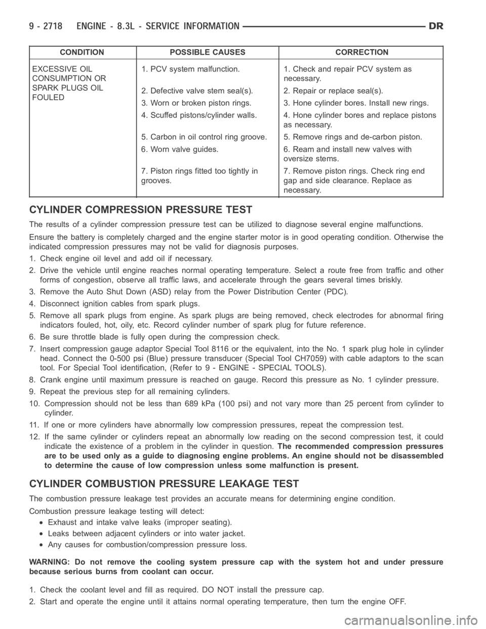
CONDITION POSSIBLE CAUSES CORRECTION
EXCESSIVE OIL
CONSUMPTION OR
SPARK PLUGS OIL
FOULED1. PCV system malfunction. 1. Check and repair PCV system as
necessary.
2. Defective valve stem seal(s). 2. Repair or replace seal(s).
3. Worn or broken piston rings. 3. Hone cylinder bores. Install new rings.
4. Scuffed pistons/cylinder walls. 4. Hone cylinder bores and replace pistons
as necessary.
5. Carbon in oil control ring groove. 5. Remove rings and de-carbon piston.
6. Worn valve guides. 6. Ream and install new valves with
oversize stems.
7. Piston rings fitted too tightly in
grooves.7. Remove piston rings. Check ring end
gap and side clearance. Replace as
necessary.
CYLINDER COMPRESSION PRESSURE TEST
The results of a cylinder compressionpressure test can be utilized to diagnose several engine malfunctions.
Ensurethebatteryiscompletelychargedandtheenginestartermotorisingood operating condition. Otherwise the
indicated compression pressures may not be valid for diagnosis purposes.
1. Check engine oil level and add oil if necessary.
2. Drive the vehicle until engine reaches normal operating temperature. Select a route free from traffic and other
forms of congestion, observe all traffic laws, and accelerate through thegears several times briskly.
3. Remove the Auto Shut Down (ASD) relay from the Power Distribution Center(PDC).
4. Disconnect ignition cables from spark plugs.
5. Remove all spark plugs from engine. As spark plugs are being removed, check electrodes for abnormal firing
indicators fouled, hot, oily, etc. Record cylinder number of spark plug for future reference.
6. Be sure throttle blade is fully open during the compression check.
7. Insert compression gauge adaptor Special Tool 8116 or the equivalent, into the No. 1 spark plug hole in cylinder
head. Connect the 0-500 psi (Blue) pressure transducer (Special Tool CH7059) with cable adaptors to the scan
tool. For Special Tool identification, (Refer to 9 - ENGINE - SPECIAL TOOLS).
8. Crank engine until maximum pressure is reached on gauge. Record this pressure as No. 1 cylinder pressure.
9. Repeat the previous step for all remaining cylinders.
10. Compression should not be less than 689 kPa (100 psi) and not vary more than 25 percent from cylinder to
cylinder.
11. If one or more cylinders have abnormally low compression pressures, repeat the compression test.
12. If the same cylinder or cylinders repeat an abnormally low reading on the second compression test, it could
indicate the existence of a problem in the cylinder in question.The recommended compression pressures
are to be used only as a guide to diagnosing engine problems. An engine should not be disassembled
to determine the cause of low compression unless some malfunction is present.
CYLINDER COMBUSTIONPRESSURE LEAKAGE TEST
The combustion pressure leakage test provides an accurate means for determining engine condition.
Combustion pressure leakage testing will detect:
Exhaust and intake valve leaks (improper seating).
Leaks between adjacent cylinders or into water jacket.
Any causes for combustion/compression pressure loss.
WARNING: Do not remove the cooling system pressure cap with the system hot and under pressure
because serious burns from coolant can occur.
1. Check the coolant level and fill as required. DO NOT install the pressurecap.
2. Start and operate the engine until it attains normal operating temperature, then turn the engine OFF.
Page 2028 of 5267
3. Clean spark plug recesses with compressed air.
4. Remove the spark plugs.
5. Remove the oil fill cap.
6. Remove the air cleaner.
7. Calibrate the tester according to the manufacturer’s instructions. The shop air source for testing should maintain
483 kPa (70 psi) minimum, 1,379 kPa (200 psi) maximum, with 552 kPa (80 psi) recommended.
8. Perform the test procedures on each cylinder according to the tester manufacturer’s instructions. While testing,
listen for pressurized air escaping through the throttle body, tailpipe and oil filler cap opening. Check for bubbles
in the coolant pressure bottle.
All gauge pressure indications should be equal, with no more than 25 percent leakage per cylinder.
FOR EXAMPLE:At 552 kPa (80 psi) input pressure, a minimum of 414 kPa (60 psi) should be maintained in the
cylinder.
CYLINDER HEAD GASKET FAILURE DIAGNOSIS
A cylinder head gasket leak can be located between adjacent cylinders, between a cylinder and the adjacent water
jacket, or an external coolant leak may be present.
Possible indications of the cylinder head gasket leaking between adjacent cylinders are:
Loss of engine power
Engine misfiring
Poor fuel economy
Possible indications of the cylinder head gasket leaking between a cylinder and an adjacent water jacket are:
Engine overheating
Loss of coolant
Excessive steam (white smoke) emitting from exhaust
Coolant foaming
CYLINDER-TO-CYLINDER LEAKAGE TEST
To determine if an engine cylinder head gasket is leaking between adjacentcylinders, follow the procedures in Cyl-
inder Compression Pressure Test in this section. An engine cylinder head gasket leaking between adjacent cylinders
will result in approximately a 50-70% reduction in compression pressure.Cylinders adjacent to each other will both
have low compression.
CYLINDER-TO-WATER JACKET LEAKAGE TEST
WARNING: Use extreme caution when the engine is operating with coolant pressure cap removed.
VISUAL TEST METHOD
With the engine cool, remove the coolant pressure cap. Start the engine andallow it to warm up until thermostat
opens.
If a large combustion/compression pressure leak exists, bubbles will be visible in the coolant.
COOLING SYSTEM TESTER METHOD
WARNING: With cooling system tester in place, pressure will build up fast.Excessive pressure built up, by
continuous engine operation, must be released to a safe pressure point. Never permit pressure to exceed
138 kpa (20 psi).
Install Cooling System Tester 7700 or equivalent to pressure cap neck. Start the engine and observe the tester’s
pressure gauge. If gauge pulsates with every power stroke of a cylinder a combustion pressure leak is evident.
Page 2040 of 5267
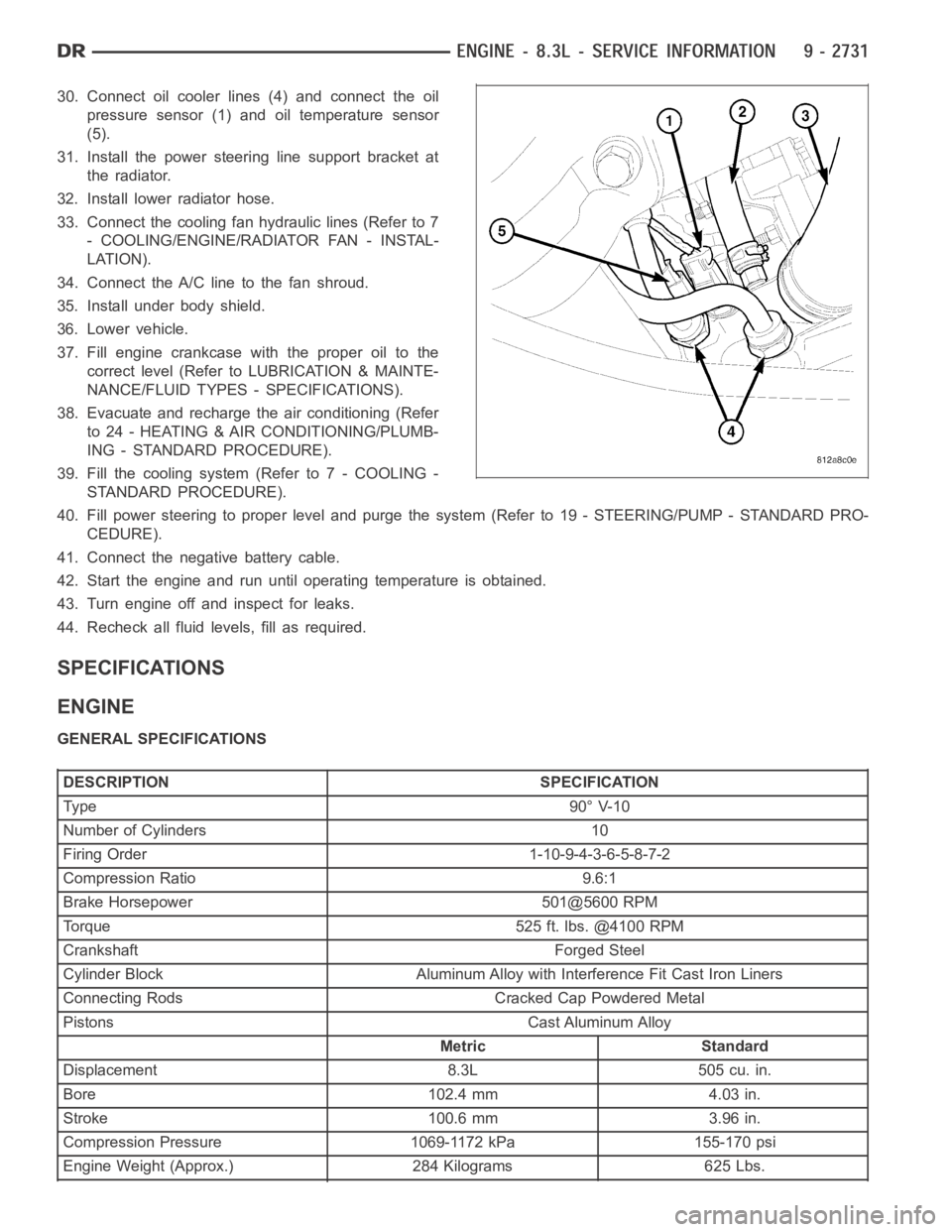
30. Connect oil cooler lines (4) and connect the oil
pressure sensor (1) and oil temperature sensor
(5).
31. Install the power steering line support bracket at
the radiator.
32. Install lower radiator hose.
33. Connect the cooling fan hydraulic lines (Refer to 7
- COOLING/ENGINE/RADIATOR FAN - INSTAL-
LATION).
34. Connect the A/C line to the fan shroud.
35. Install under body shield.
36. Lower vehicle.
37. Fill engine crankcase with the proper oil to the
correct level (Refer to LUBRICATION & MAINTE-
NANCE/FLUID TYPES - SPECIFICATIONS).
38. Evacuate and recharge the air conditioning (Refer
to 24 - HEATING & AIR CONDITIONING/PLUMB-
ING - STANDARD PROCEDURE).
39. Fill the cooling system (Refer to 7 - COOLING -
STANDARD PROCEDURE).
40. Fill power steering to proper leveland purge the system (Refer to 19 - STEERING/PUMP - STANDARD PRO-
CEDURE).
41. Connect the negative battery cable.
42. Start the engine and run until operating temperature is obtained.
43. Turn engine off and inspect for leaks.
44. Recheck all fluid levels, fill as required.
SPECIFICATIONS
ENGINE
GENERAL SPECIFICATIONS
DESCRIPTION SPECIFICATION
Ty pe 9 0° V-1 0
Number of Cylinders 10
Firing Order 1-10-9-4-3-6-5-8-7-2
Compression Ratio 9.6:1
Brake Horsepower 501@5600 RPM
Torque 525 ft. lbs. @4100 RPM
Crankshaft Forged Steel
Cylinder Block Aluminum Alloy with Interference Fit Cast Iron Liners
Connecting Rods Cracked Cap Powdered Metal
Pistons Cast Aluminum Alloy
Metric Standard
Displacement 8.3L 505 cu. in.
Bore 102.4 mm 4.03 in.
Stroke 100.6 mm 3.96 in.
Compression Pressure 1069-1172 kPa 155-170 psi
Engine Weight (Approx.) 284 Kilograms 625 Lbs.
Page 2042 of 5267
DESCRIPTIONSPECIFICATION
Metric Standard
Piston Size 102.314-102.332 mm. 4.0281-4.0288 in.
Clearance at Top of Skirt (12 mm
from bottom)0.025-0.055 mm. 0.0010-0.0022 in.
Land Clearance (Diametrical) 0.771-0.808 mm -0.036–0.042 in.
Weight 429-439 grams 15.13-15.49 oz.
Piston Length 57.0 mm 2.24 in.
Piston Pin Boar Diameter 23.940-23.978 mm 0.9425-0.9440 in.
Piston Pin Boar Offset 0.800 mm 0.031 in.
Piston Ring Groove Depth No.1 91.55-91.88 mm 3.604-3.614 in.
Piston Ring Groove Depth No.2 90.75-91.00 mm 3.573-3.583 in.
Piston Ring Groove Depth No.3 92.53-92.79 mm 3.643-3.653 in.
PISTON PINS
DESCRIPTIONSPECIFICATION
Metric Standard
Clearance in Piston 0.009-0.022 mm 0.0004-0.0009 in.
Clearance in Connecting Rod 0.017-0.061 mm 0.0007-0.0024 in.
Diameter 23.995-24.000 mm 0.9447-0.9449 in.
Length 73.35 mm 2.888 in.
End Play None
PISTON RING
DESCRIPTIONSPECIFICATION
Metric Standard
Piston Ring End Gap
Top Compression Ring 0.20-0.36 mm 0.008-0.014 in.
Second Compression Ring 0.56-0.79 mm 0.022-0.031 in.
Oil Control (Steel Rails) 0.25-0.76 mm 0.010-0.030 in.
Wear Limit-Top Compression Ring 0.63 mm 0.025 in.
Wear Limit-2nd Compression Ring 1.40 mm 0.055 in.
Wear Limit-Oil Control Steel Rails 1.64 mm 0.065 in.
Piston Ring Side Clearance
Top and 2nd Compression Ring 0.040-0.085 mm 0.0016-0.0033 in.
Oil Ring (Steel Ring) 0.046-0.201 mm 0.0018-0.0079 in.
Wear Limit- Top and 2nd Ring 0.10 mm 0.004 in.
Wear Limit Oil Ring Pack 0.216 mm 0.0085 in.
Piston Ring Width
Compression Rings 1.407-1.490 mm 0.0579-0.0586 in.
Oil Ring (Steel Rails) 0.447-0.473 mm 0.0176-0.0186 in.
CAMSHAFT
Page 2072 of 5267
SPRINGS/SEALS-VALVE
DIAGNOSIS AND TESTING
VA LV E S P R I N G T E S T I N G
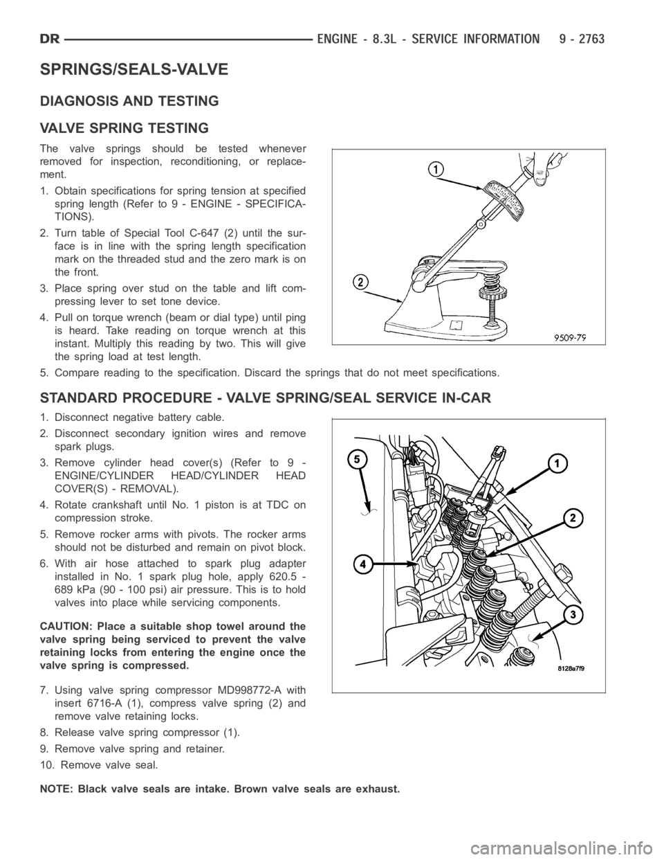
The valve springs should be tested whenever
removed for inspection, reconditioning, or replace-
ment.
1. Obtain specifications for spring tension at specified
spring length (Refer to 9 - ENGINE - SPECIFICA-
TIONS).
2. Turn table of Special Tool C-647 (2) until the sur-
face is in line with the spring length specification
mark on the threaded stud and the zero mark is on
the front.
3.Placespringoverstudonthetableandliftcom-
pressing lever to set tone device.
4. Pull on torque wrench (beam or dial type) until ping
is heard. Take reading on torque wrench at this
instant. Multiply this reading by two. This will give
the spring load at test length.
5. Compare reading to the specification. Discard the springs that do not meet specifications.
STANDARD PROCEDURE - VALVE SPRING/SEAL SERVICE IN-CAR
1. Disconnect negative battery cable.
2. Disconnect secondary ignition wires and remove
spark plugs.
3. Remove cylinder head cover(s) (Refer to 9 -
ENGINE/CYLINDER HEAD/CYLINDER HEAD
COVER(S) - REMOVAL).
4. Rotate crankshaft until No. 1 piston is at TDC on
compression stroke.
5. Remove rocker arms with pivots. The rocker arms
should not be disturbed and remain on pivot block.
6. With air hose attached to spark plug adapter
installed in No. 1 spark plug hole, apply 620.5 -
689 kPa (90 - 100 psi) air pressure. This is to hold
valves into place while servicing components.
CAUTION: Place a suitable shop towel around the
valve spring being serviced to prevent the valve
retaining locks from entering the engine once the
valve spring is compressed.
7. Using valve spring compressor MD998772-A with
insert 6716-A (1), compress valve spring (2) and
remove valve retaining locks.
8. Release valve spring compressor (1).
9. Remove valve spring and retainer.
10. Remove valve seal.
NOTE: Black valve seals are intake. Brown valve seals are exhaust.