2006 DODGE RAM SRT-10 Compression
[x] Cancel search: CompressionPage 1907 of 5267
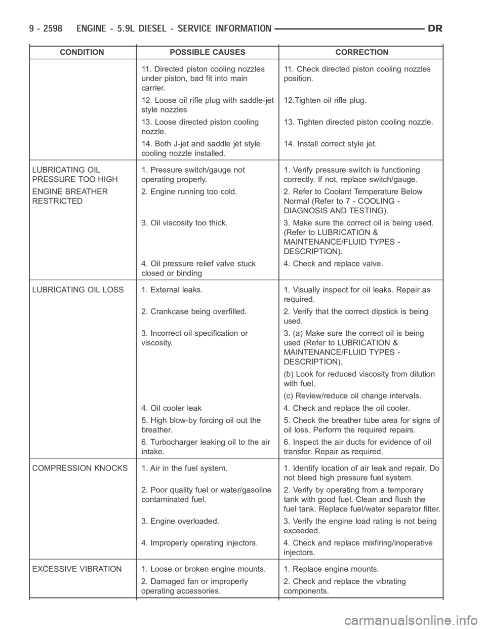
CONDITION POSSIBLE CAUSES CORRECTION
11. Directed piston cooling nozzles
under piston, bad fit into main
carrier.11. Check directed piston cooling nozzles
position.
12. Loose oil rifle plug with saddle-jet
style nozzles12.Tighten oil rifle plug.
13. Loose directed piston cooling
nozzle.13. Tighten directed piston cooling nozzle.
14. Both J-jet and saddle jet style
cooling nozzle installed.14. Install correct style jet.
LUBRICATING OIL
PRESSURE TOO HIGH1. Pressure switch/gauge not
operating properly.1. Verify pressure switch is functioning
correctly. If not, replace switch/gauge.
ENGINE BREATHER
RESTRICTED2. Engine running too cold. 2. Refer to Coolant Temperature Below
Normal (Refer to 7 - COOLING -
DIAGNOSIS AND TESTING).
3. Oil viscosity too thick. 3. Make sure the correct oil is being used.
(Refer to LUBRICATION &
MAINTENANCE/FLUID TYPES -
DESCRIPTION).
4. Oil pressure relief valve stuck
closed or binding4. Check and replace valve.
LUBRICATING OIL LOSS 1. External leaks. 1. Visually inspect for oil leaks.Repair as
required.
2. Crankcase being overfilled. 2. Verify that the correct dipstick is being
used.
3. Incorrect oil specification or
viscosity.3. (a) Make sure the correct oil is being
used (Refer to LUBRICATION &
MAINTENANCE/FLUID TYPES -
DESCRIPTION).
(b) Look for reduced viscosity from dilution
with fuel.
(c) Review/reduce oil change intervals.
4. Oil cooler leak 4. Check and replace the oil cooler.
5. High blow-by forcing oil out the
breather.5. Check the breather tube area for signs of
oil loss. Perform the required repairs.
6. Turbocharger leaking oil to the air
intake.6. Inspect the air ducts for evidence of oil
transfer. Repair as required.
COMPRESSION KNOCKS 1. Air in the fuel system. 1. Identify location of air leak and repair. Do
not bleed high pressure fuel system.
2. Poor quality fuel or water/gasoline
contaminated fuel.2. Verify by operating from a temporary
tank with good fuel. Clean and flush the
fuel tank. Replace fuel/water separator filter.
3. Engine overloaded. 3. Verify the engine load rating is not being
exceeded.
4. Improperly operating injectors. 4. Check and replace misfiring/inoperative
injectors.
EXCESSIVE VIBRATION 1. Loose or broken engine mounts. 1. Replace engine mounts.
2. Damaged fan or improperly
operating accessories.2. Check and replace the vibrating
components.
Page 1911 of 5267
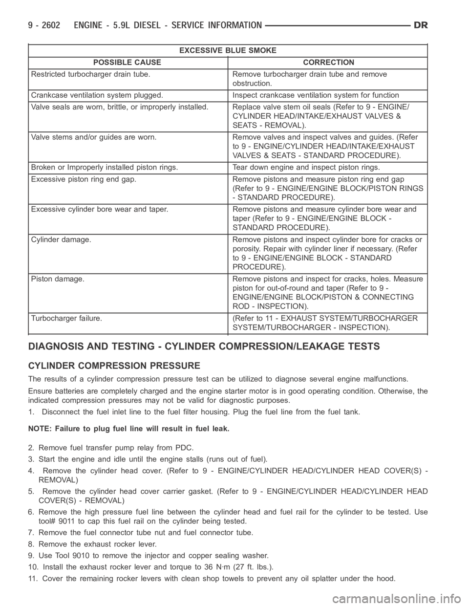
EXCESSIVE BLUE SMOKE
POSSIBLE CAUSE CORRECTION
Restricted turbocharger drain tube. Remove turbocharger drain tube and remove
obstruction.
Crankcase ventilation system plugged. Inspect crankcase ventilation system for function
Valve seals are worn, brittle, or improperly installed. Replace valve stemoilseals(Referto9-ENGINE/
CYLINDER HEAD/INTAKE/EXHAUST VALVES &
SEATS - REMOVAL).
Valve stems and/or guides are worn. Remove valves and inspect valves and guides. (Refer
to 9 - ENGINE/CYLINDER HEAD/INTAKE/EXHAUST
VALVES & SEATS - STANDARD PROCEDURE).
Broken or Improperly installed piston rings. Tear down engine and inspectpiston rings.
Excessive piston ring end gap. Remove pistons and measure piston ring end gap
(Refer to 9 - ENGINE/ENGINE BLOCK/PISTON RINGS
- STANDARD PROCEDURE).
Excessive cylinder bore wear and taper. Remove pistons and measure cylinder bore wear and
taper (Refer to 9 - ENGINE/ENGINE BLOCK -
STANDARD PROCEDURE).
Cylinder damage. Remove pistons and inspect cylinder bore for cracks or
porosity. Repair with cylinder liner if necessary. (Refer
to 9 - ENGINE/ENGINE BLOCK - STANDARD
PROCEDURE).
Piston damage. Remove pistons and inspect for cracks, holes. Measure
piston for out-of-round and taper (Refer to 9 -
ENGINE/ENGINE BLOCK/PISTON & CONNECTING
ROD - INSPECTION).
Turbocharger failure. (Refer to 11 - EXHAUST SYSTEM/TURBOCHARGER
SYSTEM/TURBOCHARGER - INSPECTION).
DIAGNOSIS AND TESTING - CYLINDER COMPRESSION/LEAKAGE TESTS
CYLINDER COMPRESSION PRESSURE
The results of a cylinder compressionpressure test can be utilized to diagnose several engine malfunctions.
Ensure batteries are completely charged and the engine starter motor is ingood operating condition. Otherwise, the
indicated compression pressures may not be valid for diagnostic purposes.
1. Disconnect the fuel inlet line to the fuel filter housing. Plug the fuel line from the fuel tank.
NOTE: Failure to plug fuel line will result in fuel leak.
2. Remove fuel transfer pump relay from PDC.
3. Start the engine and idle until the engine stalls (runs out of fuel).
4. Remove the cylinder head cover. (Refer to 9 - ENGINE/CYLINDER HEAD/CYLINDER HEAD COVER(S) -
REMOVAL)
5. Remove the cylinder head cover carrier gasket. (Refer to 9 - ENGINE/CYLINDER HEAD/CYLINDER HEAD
COVER(S) - REMOVAL)
6. Remove the high pressure fuel line between the cylinder head and fuel rail for the cylinder to be tested. Use
tool# 9011 to cap this fuel rail on the cylinder being tested.
7. Remove the fuel connector tube nut and fuel connector tube.
8. Remove the exhaust rocker lever.
9. Use Tool 9010 to remove the injector and copper sealing washer.
10. Install the exhaust rocker lever and torque to 36 Nꞏm (27 ft. lbs.).
11. Cover the remaining rocker levers with clean shop towels to prevent anyoil splatter under the hood.
Page 1912 of 5267
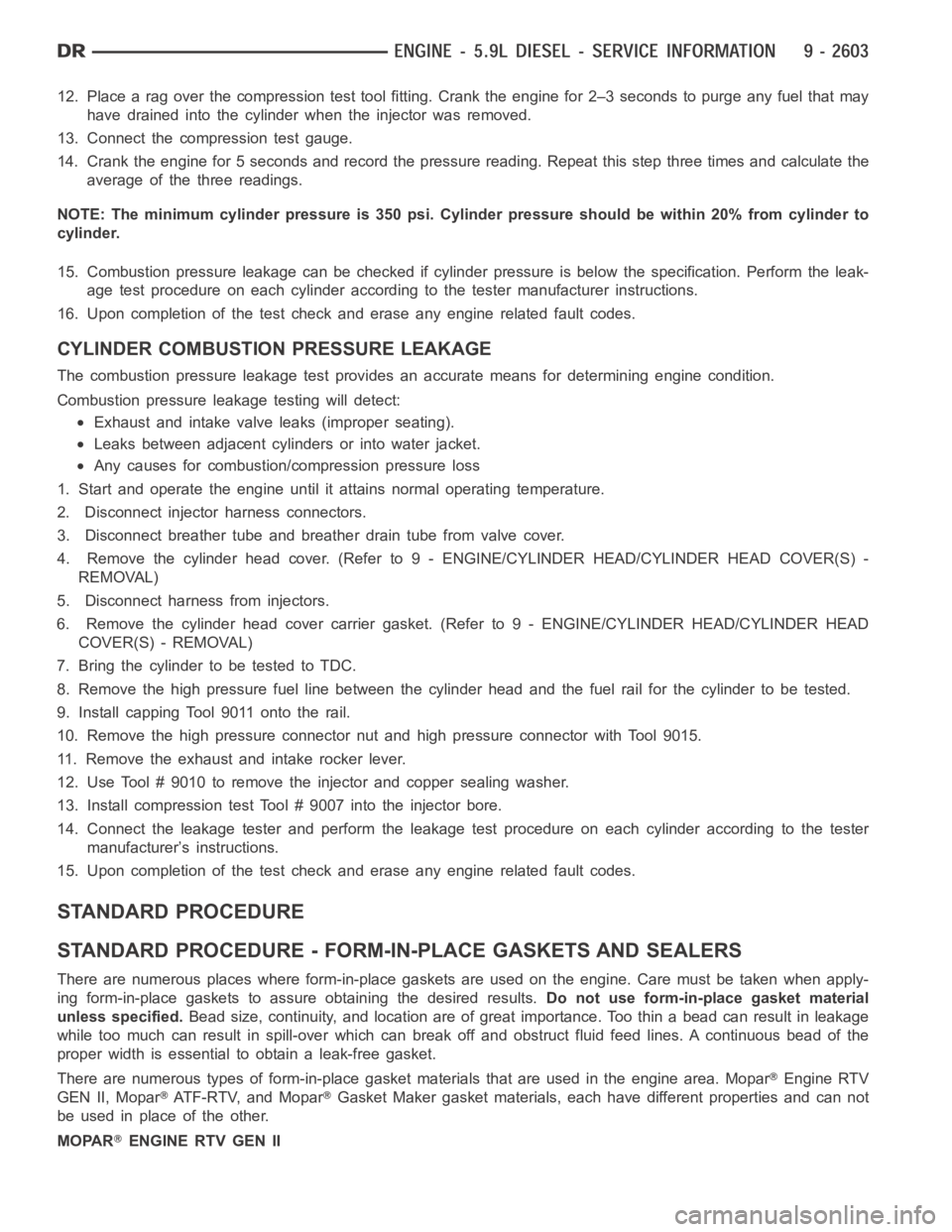
12. Place a rag over the compression test tool fitting. Crank the engine for2–3 seconds to purge any fuel that may
have drained into the cylinder when the injector was removed.
13. Connect the compression test gauge.
14. Crank the engine for 5 seconds and record the pressure reading. Repeat this step three times and calculate the
average of the three readings.
NOTE: The minimum cylinder pressure is 350 psi. Cylinder pressure should be within 20% from cylinder to
cylinder.
15. Combustion pressure leakage can be checked if cylinder pressure is below the specification. Perform the leak-
age test procedure on each cylinder according to the tester manufacturer instructions.
16. Upon completion of the test check and erase any engine related fault codes.
CYLINDER COMBUSTION PRESSURE LEAKAGE
The combustion pressure leakage test provides an accurate means for determining engine condition.
Combustion pressure leakage testing will detect:
Exhaust and intake valve leaks (improper seating).
Leaks between adjacent cylinders or into water jacket.
Any causes for combustion/compression pressure loss
1. Start and operate the engine until it attains normal operating temperature.
2. Disconnect injector harness connectors.
3. Disconnect breather tube and breather drain tube from valve cover.
4. Remove the cylinder head cover. (Refer to 9 - ENGINE/CYLINDER HEAD/CYLINDER HEAD COVER(S) -
REMOVAL)
5. Disconnect harness from injectors.
6. Remove the cylinder head cover carrier gasket. (Refer to 9 - ENGINE/CYLINDER HEAD/CYLINDER HEAD
COVER(S) - REMOVAL)
7. BringthecylindertobetestedtoTDC.
8. Remove the high pressure fuel line between the cylinder head and the fuelrail for the cylinder to be tested.
9. Install capping Tool 9011 onto the rail.
10. Remove the high pressure connector nut and high pressure connector with Tool 9015.
11. Remove the exhaust and intake rocker lever.
12. Use Tool # 9010 to remove the injector and copper sealing washer.
13. Install compression test Tool # 9007 into the injector bore.
14. Connect the leakage tester and perform the leakage test procedure on each cylinder according to the tester
manufacturer’s instructions.
15. Upon completion of the test check and erase any engine related fault codes.
STANDARD PROCEDURE
STANDARD PROCEDURE - FORM-IN-PLACE GASKETS AND SEALERS
There are numerous places where form-in-place gaskets are used on the engine. Care must be taken when apply-
ing form-in-place gaskets to assure obtaining the desired results.Do not use form-in-place gasket material
unless specified.Bead size, continuity, and location are of great importance. Too thin a bead can result in leakage
while too much can result in spill-overwhich can break off and obstruct fluid feed lines. A continuous bead of the
proper width is essential to obtain a leak-free gasket.
There are numerous types of form-in-place gasket materials that are used in the engine area. Mopar
Engine RTV
GEN II, Mopar
ATF-RTV, and MoparGasket Maker gasket materials, each have different properties and can not
be used in place of the other.
MOPAR
ENGINE RTV GEN II
Page 1925 of 5267
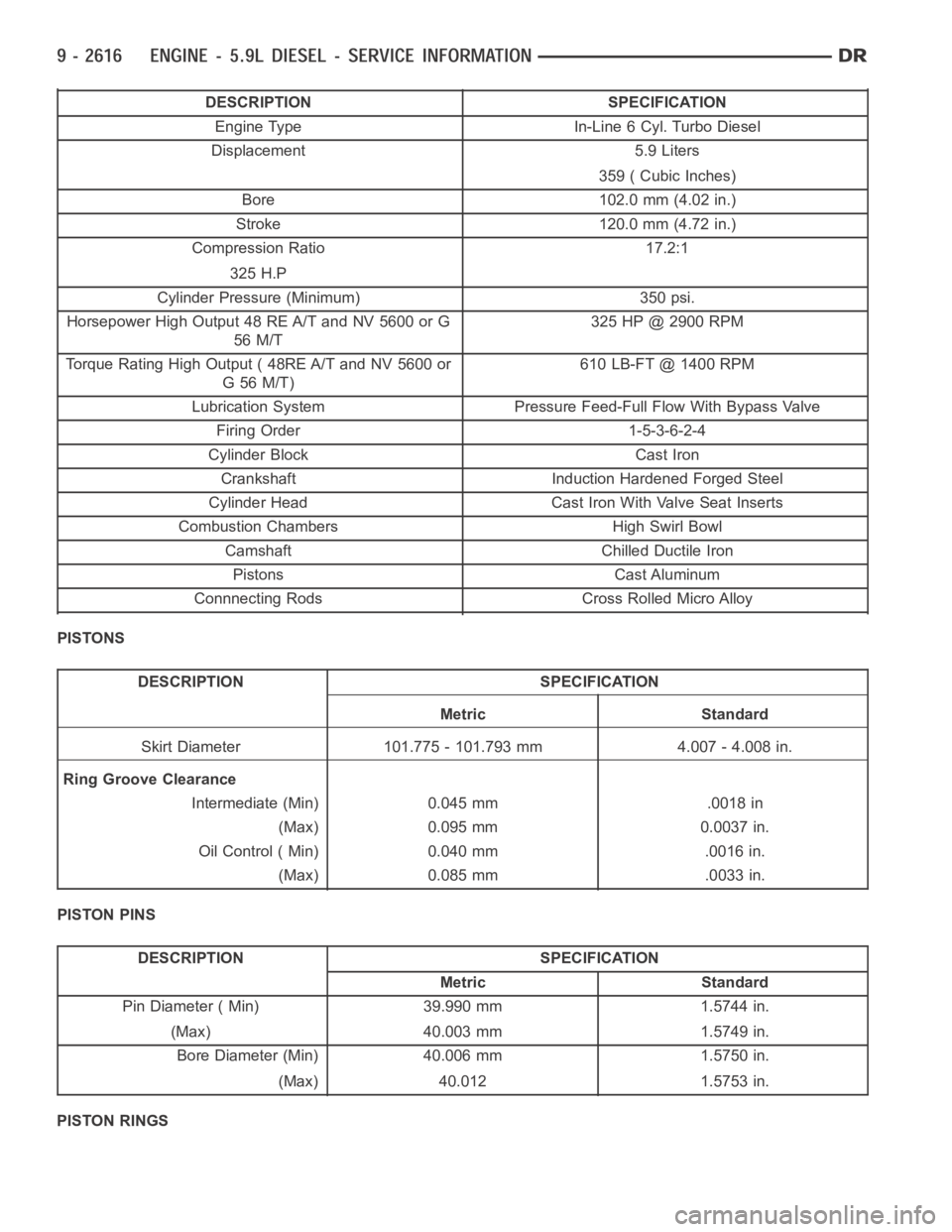
DESCRIPTION SPECIFICATION
Engine Type In-Line 6 Cyl. Turbo Diesel
Displacement 5.9 Liters
359 ( Cubic Inches)
Bore 102.0 mm (4.02 in.)
Stroke 120.0 mm (4.72 in.)
Compression Ratio 17.2:1
325 H.P
Cylinder Pressure (Minimum) 350 psi.
Horsepower High Output 48 RE A/T and NV 5600 or G
56 M/T325 HP @ 2900 RPM
Torque Rating High Output ( 48RE A/T and NV 5600 or
G56M/T)610 LB-FT @ 1400 RPM
Lubrication System Pressure Feed-Full Flow With Bypass Valve
Firing Order 1-5-3-6-2-4
Cylinder Block Cast Iron
Crankshaft Induction Hardened Forged Steel
Cylinder Head Cast Iron With Valve Seat Inserts
Combustion Chambers High Swirl Bowl
Camshaft Chilled Ductile Iron
Pistons Cast Aluminum
Connnecting Rods Cross Rolled Micro Alloy
PISTONS
DESCRIPTION SPECIFICATION
Metric Standard
Skirt Diameter 101.775 - 101.793 mm 4.007 - 4.008 in.
Ring Groove Clearance
Intermediate (Min) 0.045 mm .0018 in
(Max) 0.095 mm 0.0037 in.
Oil Control ( Min) 0.040 mm .0016 in.
(Max) 0.085 mm .0033 in.
PISTON PINS
DESCRIPTION SPECIFICATION
Metric Standard
Pin Diameter ( Min) 39.990 mm 1.5744 in.
(Max) 40.003 mm 1.5749 in.
Bore Diameter (Min) 40.006 mm 1.5750 in.
(Max) 40.012 1.5753 in.
PISTON RINGS
Page 1929 of 5267
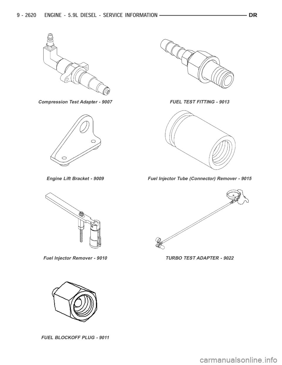
Compression Test Adapter - 9007
Engine Lift Bracket - 9009
Fuel Injector Remover - 9010
FUEL BLOCKOFF PLUG - 9011
FUEL TEST FITTING - 9013
Fuel Injector Tube (Connector) Remover - 9015
TURBO TEST ADAPTER - 9022
Page 1986 of 5267
PISTON & CONNECTING ROD
DESCRIPTION
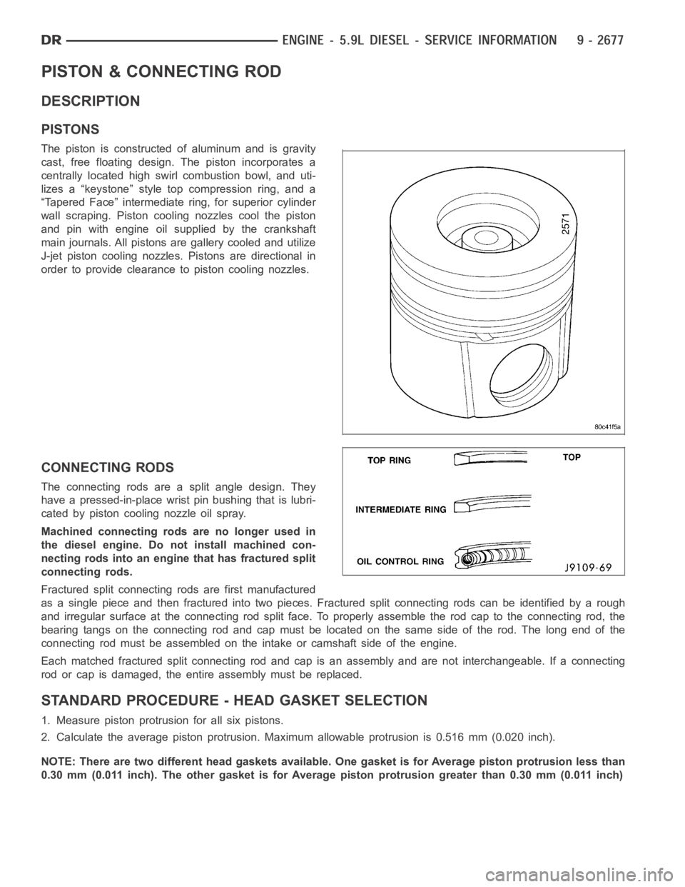
PISTONS
The piston is constructed of aluminum and is gravity
cast, free floating design. The piston incorporates a
centrally located high swirl combustion bowl, and uti-
lizes a “keystone” style top compression ring, and a
“Tapered Face” intermediate ring, for superior cylinder
wall scraping. Piston cooling nozzles cool the piston
and pin with engine oil supplied by the crankshaft
main journals. All pistons are gallery cooled and utilize
J-jet piston cooling nozzles. Pistons are directional in
order to provide clearance to piston cooling nozzles.
CONNECTING RODS
The connecting rods are a split angle design. They
have a pressed-in-place wrist pin bushing that is lubri-
cated by piston cooling nozzle oil spray.
Machined connecting rods are no longer used in
the diesel engine. Do not install machined con-
necting rods into an engine that has fractured split
connecting rods.
Fractured split connecting rods are first manufactured
asasinglepieceandthenfracturedintotwopieces.Fracturedsplitconnecting rods can be identified by a rough
and irregular surface at the connecting rod split face. To properly assemble the rod cap to the connecting rod, the
bearing tangs on the connecting rod and cap must be located on the same side of the rod. The long end of the
connecting rod must be assembled on theintake or camshaft side of the engine.
Each matched fractured split connecting rod and cap is an assembly and are not interchangeable. If a connecting
rod or cap is damaged, the entire assembly must be replaced.
STANDARD PROCEDURE - HEAD GASKET SELECTION
1. Measure piston protrusion for all six pistons.
2. Calculate the average piston protrusion. Maximum allowable protrusion is 0.516 mm (0.020 inch).
NOTE: There are two different head gaskets available. One gasket is for Average piston protrusion less than
0.30 mm (0.011 inch). The other gasket is for Average piston protrusion greater than 0.30 mm (0.011 inch)
Page 1991 of 5267
RINGS - PISTON
STANDARD PROCEDURE - PISTON RING FITTING
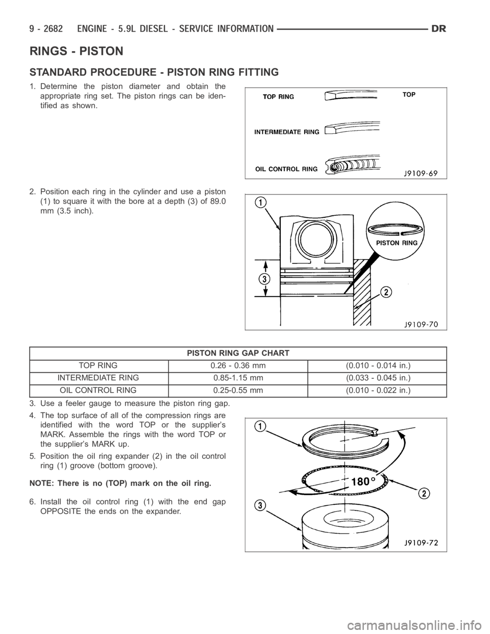
1. Determine the piston diameter and obtain the
appropriate ring set. The piston rings can be iden-
tified as shown.
2. Position each ring in the cylinder and use a piston
(1) to square it with the bore at a depth (3) of 89.0
mm (3.5 inch).
PISTON RING GAP CHART
TOP RING 0.26 - 0.36 mm (0.010 - 0.014 in.)
INTERMEDIATE RING 0.85-1.15 mm (0.033 - 0.045 in.)
OIL CONTROL RING 0.25-0.55 mm (0.010 - 0.022 in.)
3. Use a feeler gauge to measure the piston ring gap.
4. The top surface of all of the compression rings are
identified with the word TOP or the supplier’s
MARK. Assemble the rings with the word TOP or
the supplier’s MARK up.
5. Position the oil ring expander (2) in the oil control
ring (1) groove (bottom groove).
NOTE: There is no (TOP) mark on the oil ring.
6. Install the oil control ring (1) with the end gap
OPPOSITE the ends on the expander.
Page 1992 of 5267
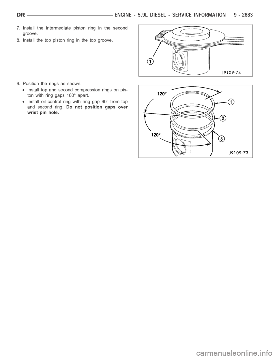
7. Install the intermediate piston ring in the second
groove.
8. Install the top piston ring in the top groove.
9. Position the rings as shown.
Install top and second compression rings on pis-
ton with ring gaps 180° apart.
Install oil control ring with ring gap 90° from top
and second ring.Do not position gaps over
wrist pin hole.