Page 1937 of 5135
A62378
+B
HT
E1
� �
� �
Bank 2 Sensor 2:
A62378
+B
HT
E1
� �
� �
Bank 1 Sensor 1, 2:
± EMISSION CONTROLEMISSION CONTROL SYSTEM (1AZ±FSE)
12±15
AVENSIS REPAIR MANUAL (RM1018E)
(b) Bank 2 Sensor 2:
(1) Using an ohmmeter, measure the resistance be-
tween the terminals.
Resistance:
Terminal No.Resistance
1 (HT) ± 2 (+B)11 to 16 � at 20 �C (68 �F)
1 (HT) ± 4 (E1)No Continuity
If the resistance is not as specified, replace the sensor.
(c) Bank 1 Sensor 1, 2:
(1) Using an ohmmeter, measure the resistance be-
tween the terminals.
Resistance:
Terminal No.Resistance
1 (HT) ± 2 (+B)11 to 16 � at 20 �C (68 �F)
1 (HT) ± 4 (E1)No Continuity
If the resistance is not as specified, replace the sensor.
Page 1938 of 5135

12±11
AVENSIS REPAIR MANUAL (RM1018E)
EMISSION CONTROL SYSTEM (1AZ±FSE)
ON±VEHICLE INSPECTI")
1209G±02
A59588
E1
OX1AOX1B
OX2B OX2A
ECM
A77114
± EMISSION CONTROLEMISSION CONTROL SYSTEM (1AZ±FSE)
12±11
AVENSIS REPAIR MANUAL (RM1018E)
EMISSION CONTROL SYSTEM (1AZ±FSE)
ON±VEHICLE INSPECTION
1. INSPECT AIR±FUEL RATIO COMPENSATION SYS-
TEM
HINT:
You can also check the system by choosing ºDATA MONITOR/
O
2 SENSOR OUTPUT VOLTAGEº on the monitor of the hand±
held tester.
(a) Connect the hand±held tester to the following each pair
of the ECM terminals:
(1) Terminals 21 (OX1B) and 1 (E1)
(2) Terminals 22 (OX1A) and 1 (E1)
(3) Terminals 23 (OX2A) and 1 (E1)
(4) Terminals 29 (OX2B) and 1 (E1)
CAUTION:
Connect test leads from the back side of the connector with
the ECU connected.
(b) Warm up the heated oxygen sensor with the engine
speed at 2,500 rpm for approximately 2 minutes.
(c) Confirm that the voltage output varies between 0V to 1V
with the engine speed at 2,500 rpm.
OK:
The voltage output varies more than 8 times in 10 se-
conds.
CAUTION:
�Perform the check immediately after the warming up.
�If the voltage variation could not be verified, warm up
the heated oxygen sensor again.
2. INSPECT FUEL CUT OFF RPM
(a) Increase the engine speed to at least 3,500 rpm.
(b) Use a sound scope to check for injector operating sounds.
(c) Check that the injector operating sounds stops momentarily and then resumes that when the throttle
lever is released.
3. INSPECT EVAPORATIVE EMISSION CONTROL SYS-
TEM
(a) After starting the engine, disconnect the vacuum hose
shown in the illustration.
(b) Check if vacuum occurs at the VSV port when choosing
ºACTIVE TESTº and ºPURGE VSVº according to the dis-
play on hand±held tester.
(c) Finish ºACTIVE TESTº, then reconnect the vacuum hose.
(d) After entering to ºECU DATA MONITORº on the hand±
held tester, choose ºPURGE VSVº to check the operation
of the purge VSV.
(e) After driving the vehicle with a warm engine, confirm that
the VSV turns from off on to.
Page 1941 of 5135

12±9
AVENSIS REPAI")
A77115
Ohmmeter
Resistance
A77116
Ohmmeter
No continuity
A77117
Air E F
A77118
Air E
F
Battery
A61829
+B HT
E1 Bank 1 Sensor 1:
± EMISSION CONTROLEMISSION CONTROL SYSTEM (1AZ±FE)
12±9
AVENSIS REPAIR MANUAL (RM1018E)
4. INSPECT VACUUM SWITCHING VALVE ASSY NO.1
(a) Inspect VSV for open circuit.
(1) Using an ohmmeter, measure resistance between
the terminals.
Resistance: 26 to 30 � at 20�C (68�F)
If the resistance is not as specified, replace the VSV.
(b) Inspect the VSV for ground.
(1) Using an ohmmeter, check that there is no continu-
ity between each terminal and the body.
If there is continuity, replace the VSV.
(c) Inspect the VSV operation.
(1) Check that air flows with a little difficulty from port E
to port F.
(2) Apply battery voltage across the terminals.
(3) Check that air flows from port E to port F.
If operation is not as specified, replace the VSV.
5. INSPECT AIR FUEL RATIO SENSOR
(a) Bank 1 Sensor 1:
(1) Using an ohmmeter, measure the resistance be-
tween the terminals.
Resistance:
Terminal No.Resistance
1 (HT) ± 2 (+B)1.8 to 3.4 � at 20 �C (68 �F)
1 (HT) ± (+B)5.0 to 7.5 � at 500 �C (932 �F)
1 (HT) ± 4 (E1)No Continuity
If the resistance is not as specified, replace the sensor.
Page 1942 of 5135
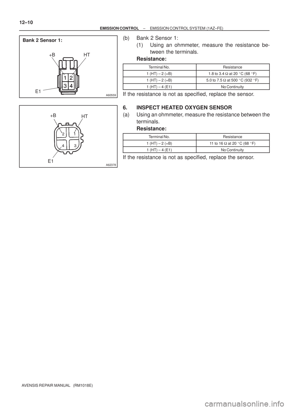
A60559
+B HT
Bank 2 Sensor 1:
E1
A62378
+B
HT
E1
� �
� �
12±10
± EMISSION CONTROLEMISSION CONTROL SYSTEM (1AZ±FE)
AVENSIS REPAIR MANUAL (RM1018E)
(b) Bank 2 Sensor 1:
(1) Using an ohmmeter, measure the resistance be-
tween the terminals.
Resistance:
Terminal No.Resistance
1 (HT) ± 2 (+B)1.8 to 3.4 � at 20 �C (68 �F)
1 (HT) ± 2 (+B)5.0 to 7.5 � at 500 �C (932 �F)
1 (HT) ± 4 (E1)No Continuity
If the resistance is not as specified, replace the sensor.
6. INSPECT HEATED OXYGEN SENSOR
(a) Using an ohmmeter, measure the resistance between the
terminals.
Resistance:
Terminal No.Resistance
1 (HT) ± 2 (+B)11 to 16 � at 20 �C (68 �F)
1 (HT) ± 4 (E1)No Continuity
If the resistance is not as specified, replace the sensor.
Page 1943 of 5135

AVENSIS REPAIR MANUAL (RM1018E)
EMISSION CONTROL SYSTEM (1AZ±FE)
ON±VEHICLE INSPECTION
1. INSPECT")
1209E±02
A65749
E1
OX2BOX1B
ECM
A77114
12±6
± EMISSION CONTROLEMISSION CONTROL SYSTEM (1AZ±FE)
AVENSIS REPAIR MANUAL (RM1018E)
EMISSION CONTROL SYSTEM (1AZ±FE)
ON±VEHICLE INSPECTION
1. INSPECT AIR±FUEL RATIO COMPENSATION SYS-
TEM
HINT:
You can also check the system by choosing ºDATA MONITOR/
O
2 SENSOR OUTPUT VOLTAGEº on the monitor of the hand±
held tester.
(a) Connect the hand±held tester to terminals 21 (OX1B) and
7 (E1) and to terminals 29 (OX2B) and 7 (E1) of the ECM.
CAUTION:
Connect test leads from the back side of the connector with
the ECM connected.
(b) Warm up the heated oxygen sensor with the engine
speed at 2,500 rpm for approximately 2 minutes.
(c) Confirm that the voltage output varies between 0V to 1V
with the engine speed at 2,500 rpm.
OK:
The voltage output varies more than 8 times in 10 se-
conds.
CAUTION:
�Perform the check immediately after the warming up.
�If the voltage variation could not be verified, warm up
the heated oxygen sensor again.
2. INSPECT FUEL CUT OFF RPM
(a) Increase the engine speed to at least 3,500 rpm.
(b) Use a sound scope to check for injector operating sounds.
(c) Check that injector operating sounds stops momentarily and then resumes when the throttle lever is
released.
3. INSPECT EVAPORATIVE EMISSION CONTROL SYS-
TEM
(a) After starting the engine, disconnect the vacuum hose
shown in the illustration.
(b) Check if vacuum occurs at the VSV port when choosing
ºACTIVE TESTº and ºPURGE VSVº according to the dis-
play on hand±held tester.
(c) Finish ºACTIVE TESTº, then reconnect the vacuum hose.
(d) After entering to ºECU DATA MONITORº on the hand±
held tester, choose ºPURGE VSVº to check the operation
of the purge VSV.
(e) After driving the vehicle with a warm engine, confirm that
the VSV turns from off to on.
Page 1946 of 5135

A77118
Air E
F
Battery
A60562
Cylinder Head Side
A60563
Intake Manifold Side
A64543
+B
Bank 1 Sensor 1:
HT1A
E1
A77126
HT +B
Bank 1 Sensor 2:
E1 12±4
± EMISSION CONTROLEMISSION CONTROL SYSTEM (1ZZ±FE/3ZZ±FE)
AVENSIS REPAIR MANUAL (RM1018E)
(2) Apply battery voltage across the terminals.
(3) Check that air flows from port E to port F.
If operation is not as specified, replace the VSV.
3. INSPECT VENTILATION VALVE SUB±ASSY
(a) Blow air into the cylinder head side, and check that air
passes through easily.
CAUTION:
Do not suck air through the valve. If contains petroleum
substances and is harmful.
(b) Blow air into the intake manifold side, and check that air
passes through with difficulty.
HINT:
If operation is not as specified, replace the PCV valve.
4. IINSPECT HEATED OXYGEN SENSOR
(a) Bank 1 Sensor 1:
(1) Using an ohmmeter, measure the resistance be-
tween the terminals.
Resistance:
Terminal No.Resistance
1 (HT1A) ± 2 (+B)5 to 10 � at 20 �C (68 �F)
1 (HT1A) ± 4 (E1)No Continuity
If the resistance is not as specified, replace the sensor.
(b) Bank 1 Sensor 2:
(1) Using an ohmmeter, measure the resistance be-
tween the terminals.
Resistance:
Terminal No.Resistance
1 (HT) ± 2 (+B)11 to 16 � at 20 �C (68 �F)
1 (HT) ± 4 (E1)No Continuity
If the resistance is not as specified, replace the sensor.
Page 1948 of 5135

12±1
AVENSIS REPAIR MANUAL (RM1018E)
EMISSION CONTROL SYSTEM (1ZZ±FE/3ZZ±FE)
ON±VEHICLE INSPE")
1209C±02
A65749
E1
OX1AOX1B
ECM
A66059
± EMISSION CONTROLEMISSION CONTROL SYSTEM (1ZZ±FE/3ZZ±FE)
12±1
AVENSIS REPAIR MANUAL (RM1018E)
EMISSION CONTROL SYSTEM (1ZZ±FE/3ZZ±FE)
ON±VEHICLE INSPECTION
1. INSPECT AIR±FUEL RATIO COMPENSATION SYS-
TEM
HINT:
You can also check the system by choosing ºDATA MONITOR/
O
2 SENSOR OUTPUT VOLTAGEº on the monitor of the hand±
held tester.
(a) Connect the hand±held tester to the terminals 21 (OX1B)
and 7 (E1) and to terminals 23 (OX1A) and 7 (E1) of the
ECM.
CAUTION:
Connect test leads from the back side of the connector with
the ECM connected.
(b) Warm up the heated oxygen sensor with the engine
speed at 2,500 rpm for approximately 2 minutes.
(c) Confirm that the voltage varies output between 0V to 1V
with the engine speed at 2,500 rpm.
OK:
The voltage output varies more than 8 times in 10 se-
conds.
CAUTION:
�Perform the check immediately after the warming up.
�If the voltage variation could not be verified, warm up
the heated oxygen sensor again.
2. INSPECT FUEL CUT OFF RPM
(a) Increase the engine speed to at least 3,500 rpm.
(b) Use a sound scope to check for injector operating sounds.
(c) Check that injector operating sounds stops momentarily and then resumes when the throttle lever is
released.
3. INSPECT EVAPORATIVE EMISSION CONTROL SYS-
TEM
(a) After starting the engine, disconnect the vacuum hose
shown in the illustration.
(b) Check if vacuum occurs at the VSV port when choosing
ºACTIVE TESTº and ºPURGE VSVº according to the dis-
play on hand±held tester.
(c) Finish ºACTIVE TESTº, then reconnect the vacuum.
(d) After entering to ºECU DATA MONITORº on the hand±
held tester, choose ºPURGE VSVº to check the operation
of the purge VSV.
(e) After driving the vehicle with a warm engine, confirm that
the VSV turns from off to on.
Page 1960 of 5135

(d)
(c)
±
FUEL FUEL TANK ASSY(GASOLINE)
11±93
AVENSIS REPAIR MANUAL (RM1018E)
Removal & Installation and Disassembly & Reassembly
1.DISCH")
110U5±01
A78493
A80060
w/o HID Sensor:
w/ HID Sensor:
(c)
(d)
(c)
±
FUEL FUEL TANK ASSY(GASOLINE)
11±93
AVENSIS REPAIR MANUAL (RM1018E)
Removal & Installation and Disassembly & Reassembly
1.DISCHARGE FUEL SYSTEM PRESSURE
HINT:
�1ZZ±FE/3ZZ±FE: 11±1
�1AZ±FE: 11±15
�1AZ±FSE: 11±30
2.REMOVE REAR SEAT CUSHION ASSY (SEAT FIXED TYPE) (See page 72±32)
3.REMOVE COVER, RR FLOOR SERVICE HOLE (See page 11±85)
4.DISCONNECT FUEL TANK RETURN TUBE (1AZ±FSE ENGINE TYPE)
(See page 11±85)
5.DISCONNECT FUEL TANK MAIN TUBE SUB±ASSY (See page 11±85)
6.DISCONNECT FUEL EVAPORATION TUBE SUB±ASSY NO.2 (See page 11±85)
7.REMOVE FUEL SUCTION W/PUMP & GAGE TUBE ASSY (See page 11±85)
SST 09808±14010
8. DRAIN FUEL
9. REMOVE FRONT FLOOR FOOTREST (W/O HID SENSOR)
10.REMOVE FLOOR PANEL BRACE FRONT (See page 15±2)
11. REMOVE EXHAUST PIPE ASSY CENTER(1ZZ±FE/3ZZ±FE ENGINE TYPE)
(a) Using a clip remover, remove the 2 clips. (w/o HID Sensor)
(b) Open the floor carpet. (w/o HID Sensor)
(c) Disconnect the heated oxygen sensor connector.
(d) Remove the grommet. (w/o HID Sensor)