Page 1966 of 5135

11±99
AVENSIS REPAIR MANUAL (RM1018E)
30. CONNECT FUEL TANK MAIN TUBE SUB±ASSY
(a) Push in the fuel tube c")
A81618
Push
2
1
Retainer
A77857
A78440
New Gasket
A77857
± FUELFUEL TANK ASSY (GASOLINE)
11±99
AVENSIS REPAIR MANUAL (RM1018E)
30. CONNECT FUEL TANK MAIN TUBE SUB±ASSY
(a) Push in the fuel tube connector to the pipe until it makes
ºclickº sound, and then push up the retainer to the claws
lock.
NOTICE:
�Check if there is any damage or foreign objects on the
connected part.
�After connecting, check if the fuel tube connector and
the pipe are securely connected by pulling on them.
31. CONNECT FUEL TANK RETURN TUBE (1AZ±FSE
ENGINE TYPE)
32. CONNECT FUEL TANK TO FILLER PIPE HOSE
33. CONNECT BREATHER TUBE FUEL HOSE
34. INSTALL PARKING BRAKE CABLE ASSY NO.3
Torque: 5.0 N�m (51 kgf�cm, 44 in.�lbf)
35. INSTALL PARKING BRAKE CABLE ASSY NO.2
Torque: 5.0 N�m (51 kgf�cm, 44 in.�lbf)
36. INSTALL FUEL TANK PROTECTOR NO.1
Torque: 5.4 N�m (55 kgf�cm, 48 in.�lbf)
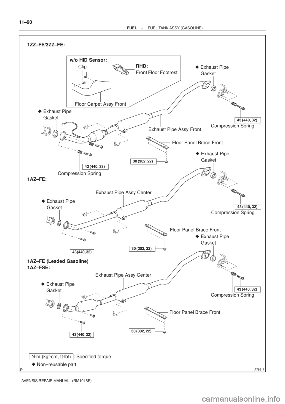
37. INSTALL EXHAUST PIPE ASSY CENTER
(1ZZ±FE/3ZZ±FE ENGINE TYPE)
(a) Compression spring inspection
(1) Using vernier calipers, measure the free length of
the compression spring.
Minimum length:
41.5 mm (1.634 in.) for front x manifold
38.5 mm (1.516 in.) for front x tail
If the free length is less than minimum, replace the compression
spring.
(b) Install each new gasket to the exhaust manifold and the
exhaust pipe front as shown in the illustration.
(c) Install the exhaust pipe front to the 2 exhaust pipe sup-
ports
(d) Tighten the 4 compression springs and 4 bolts.
Torque: 43 N�m (440 kgf�cm, 32 ft�lbf)
(e) Install the grommet. (w/o HID Sensor)
(f) Connect the heated oxygen sensor connector.
(g) Install the floor carpet with the 2 clips. (w/o HID Sensor)
38. INSTALL EXHAUST PIPE ASSY CENTER
(1AZ±FE/1AZ±FSE ENGINE TYPE)
(a) Compression spring inspection
(1) Using vernier calipers, measure the free length of
the compression spring.
Minimum length: 38.5 mm (1.516 in.)
If the free length is less than minimum, replace the compression
spring.
Page 1967 of 5135

AVENSIS REPAIR MANUAL (RM1018E)
(b)Install a new gasket to the the exhaust pipe center (ex- haust pipe tail side) as shown in the illustrat")
A78440
New Gasket
11±100
±
FUEL FUEL TANK ASSY(GASOLINE)
AVENSIS REPAIR MANUAL (RM1018E)
(b)Install a new gasket to the the exhaust pipe center (ex- haust pipe tail side) as shown in the illustration.
(c)Install a new gasket (exhaust pipe front side) and the ex-
haust pipe center to the 2 exhaust pipe supports.
(d)Tighten the 2 compression springs and 4 bolts. Torque: 43 N �m (440 kgf �cm, 32 ft �lbf)
39.ADD FUEL
40.INSTALL FUEL SUCTION W/PUMP & GAGE TUBE ASSY (See page 11±85) SST 09808±14010
41.CONNECT FUEL EVAPORATION TUBE SUB±ASSY NO.2 (See page 11±85)
42.CONNECT FUEL TANK MAIN TUBE SUB±ASSY (See page 11±85)
43.CONNECT FUEL TANK RETURN TUBE (1AZ±FSE ENGINE TYPE) (See page 11±85)
44. CHECK FOR FUEL LEAKS
HINT:
�1ZZ±FE/3ZZ±FE: 11±5
�1AZ±FE: 11±19
�1AZ±FSE: 11±33
45. CHECK FOR EXHAUST GAS LEAKS
46.INSTALL FLOOR PANEL BRACE FRONT (See page 15±2)
47. INSTALL REAR FLOOR SERVICE HOLE COVER
48.INSTALL REAR SEAT CUSHION ASSY (SEAT FIXED TYPE) (See page 72±32)
49. INSTALL FRONT FLOOR FOOTREST (W/O HID SENSOR)
Page 1969 of 5135
A78517
N´m (kgf´cm, ft´lbf) : Specified torque
� Non±reusable partRHD:
Front Floor Footrest 1ZZ±FE/3ZZ±FE:
Floor Carpet Assy FrontClip
Compression Spring � Exhaust Pipe
Gasket
Exhaust Pipe Assy Front
Floor Panel Brace Front
43 (440, 33)
30 (302, 22)
� Exhaust Pipe
Gasket
Compression Spring
43 (440, 32)
Exhaust Pipe Assy Center
43 (440, 32)
� Exhaust Pipe
Gasket
Floor Panel Brace Front
30 (302, 22)
Compression Spring
43 (440, 32)
� Exhaust Pipe
Gasket
1AZ±FE:
Exhaust Pipe Assy Center
43 (440, 32)
� Exhaust Pipe
Gasket
Floor Panel Brace Front
30 (302, 22)
Compression Spring
43 (440, 32)
� Exhaust Pipe
Gasket
1AZ±FE (Leaded Gasoline)
1AZ±FSE:
w/o HID Sensor: 11±90
± FUELFUEL TANK ASSY (GASOLINE)
AVENSIS REPAIR MANUAL (RM1018E)
Page 1988 of 5135

14±3
AVENSIS REPAIR MANUAL (RM1018E)
(3) While cranking the engine, measure the compres-
sion pressure.
Compression pressure
�
1,300 kPa (13.3 kgf�cm
2")
± ENGINE MECHANICALENGINE (1ZZ±FE/3ZZ±FE)
14±3
AVENSIS REPAIR MANUAL (RM1018E)
(3) While cranking the engine, measure the compres-
sion pressure.
Compression pressure
�
1,300 kPa (13.3 kgf�cm
2, 189 psi)
Minimum pressure: 1,000 kPa (10.2 kgf�cm
2, 145 psi)
Difference between each cylinder:
100 kPa (1.0 kgf�cm
2, 14 psi)
NOTICE:
�Always use a fully charged battery to obtain engine
speed of 250 rpm or more.
�Check other cylinder's compression pressure in the
same way.
�This measurement must be done in as short a time as
possible.
(4) If the cylinder compression in one or more cylinders
is low, pour a small amount of engine oil into the cyl-
inder through the spark plug hole and repeat steps
(1) through (3) for the cylinders that have low com-
pression.
HINT:
�If adding oil helps increase the compression, the piston
rings and/or cylinder bore may be worn or damaged.
�If pressure stays low, a valve may be sticking or seating
improperly, or there may be leakage past the gasket.
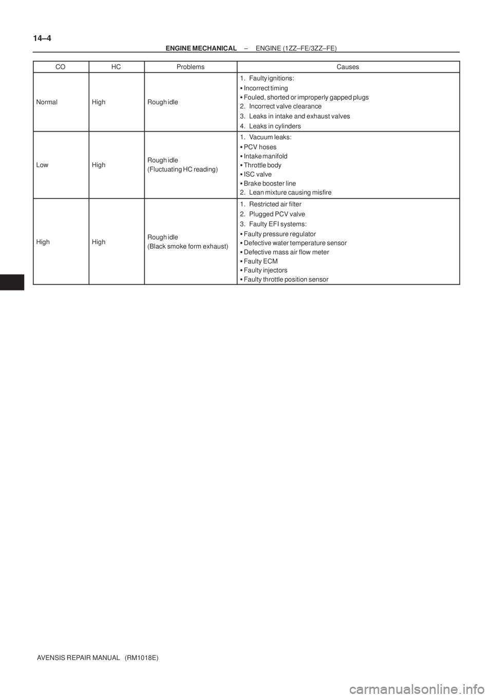
10. INSPECT CO/HC
(a) Start the engine.
(b) Run the engine at 2,500 rpm for approximately 180 seconds.
(c) Insert CO/HC meter testing probe at least 40 cm (1.3 ft) into the tailpipe during idling.
(d) Check CO/HC concentration at idle.
Idle CO concentration: 0 to 0.5 %
Idle HC concentration: Applicable local regulation
If the CO/HC concentration does not conform to specifications, perform troubleshooting in the order given
below.
�Check heated oxygen sensor operation.
�See the table below for possible causes, and then inspect and repair the applicable causes if
necessary.
Page 1989 of 5135
14±4
± ENGINE MECHANICALENGINE (1ZZ±FE/3ZZ±FE)
AVENSIS REPAIR MANUAL (RM1018E)CO
HCProblemsCauses
NormalHighRough idle
1. Faulty ignitions:
�Incorrect timing
�Fouled, shorted or improperly gapped plugs
2. Incorrect valve clearance
3. Leaks in intake and exhaust valves
4. Leaks in cylinders
LowHighRough idle
(Fluctuating HC reading)
1. Vacuum leaks:
�PCV hoses
�Intake manifold
�Throttle body
�ISC valve
�Brake booster line
2. Lean mixture causing misfire
HighHighRough idle
(Black smoke form exhaust)
1. Restricted air filter
2. Plugged PCV valve
3. Faulty EFI systems:
�Faulty pressure regulator
�Defective water temperature sensor
�Defective mass air flow meter
�Faulty ECM
�Faulty injectors
�Faulty throttle position sensor
Page 2003 of 5135

13±5
AVENSIS REPAIR MANUAL (RM1018E)
ON±VEHICLE INSPECTION
1. INSPECT INTAKE AIR SYSTEM
(a) Check for leakage or clogging")
1302Z±03
A77123
SST
A60595E2 VC
± INTAKETURBO CHARGER SYSTEM (1CD±FTV)
13±5
AVENSIS REPAIR MANUAL (RM1018E)
ON±VEHICLE INSPECTION
1. INSPECT INTAKE AIR SYSTEM
(a) Check for leakage or clogging between the air cleaner
housing and turbocharger inlet and between the turbo-
charger outlet and cylinder head.
(1) Clogged air cleaner...Clean or replace element
(2) Hoses collapsed or deformed...Repair or replace
(3) Leakage from connections...Check each connec-
tion and repair
(4) Cracks in components...Check and replace
2. INSPECT EXHAUST SYSTEM
(a) Check for leakage or clogging between the cylinder head
and turbocharger inlet and between the turbocharger out-
let and exhaust pipe.
(1) Deformed components...Repair or replace
(2) Foreign material in passages...Remove
(3) Leakage from components...Repair or replace
(4) Cracks in components...Check and replace
3. CHECK TURBOCHARGING PRESSURE
(a) Warm up the engine.
(b) Using a 3±way connector, connect SST (turbocharger
pressure gauge) to the hose leading to the intake air con-
nector.
SST 09992 ± 00242
(c) While depressing the clutch pedal, press the accelerator
pedal down to the full. Measure the turbocharging pres-
sure at maximum speed (5,100 to 5,250 rpm).
Standard pressure:
15 to 45 kPa (0.15 to 0.46 kgf/cm
2, 2.2 to 6.5 psi)
If the pressure is less than specification, check both the intake
air and exhaust systems for leakage.
If there is no leakage, check if the actuator hose has discon-
nected. If not, check the turbocharger.
If the pressure is greater than specification, check if the actua-
tor hose has disconnected or cracked. If not, check the turbo-
charger.
4. INSPECT TURBO PRESSURE SENSOR
(a) Inspect power source voltage
(1) Disconnect the turbo pressure sensor connector.
(2) Turn the ignition switch ON.
(3) Using a voltmeter, measure the voltage between
connector terminals 3 (VC) and 1 (E2) of the wiring
harness side.
Voltage: 4.5 to 5.5 V
(4) Turn the ignition switch OFF.
(5) Reconnect the turbo pressure sensor connector.
Page 2004 of 5135

E2 (±)ECM
Vacuum SST
A77125
SST
Pressure
13±6
± INTAKETURBO CHARGER SYSTEM (1CD±FTV)
AVENSIS REPAIR MANUAL (RM1018E)
(b) Inspect supply power
(1) Turn the ignition switch ON.
(2)")
A79448
PIM (+)
E2 (±)ECM
Vacuum SST
A77125
SST
Pressure
13±6
± INTAKETURBO CHARGER SYSTEM (1CD±FTV)
AVENSIS REPAIR MANUAL (RM1018E)
(b) Inspect supply power
(1) Turn the ignition switch ON.
(2) Disconnect the vacuum hose from the turbo pres-
sure sensor.
(3) Connect a voltmeter to terminals 35 (PIM) and 28
(E2) of the ECM and measure the output voltage
under atmospheric pressure.
(4) Apply vacuum to the turbo pressure sensor in 13.3
kPa (100 mmHg, 3.94 in.Hg) segments to 66.7 kPa
(500 mmHg, 19.96 in.Hg).
(5) Measure the voltage decrease from step (3) above
for each segment.
Voltage drop:
Apply Vacuum
[kPa (mmHg, in.Hg)]Voltage Decrease
[V]
13.3 (100, 3.94)0.1 to 0.3
26.7 (200, 7.87)0.3 to 0.5
40.0 (300, 11.81)0.5 to 0.7
57.3 (400, 15.75)0.7 to 0.9
66.7 (500, 19.96)0.9 to 1.0
(6) Using SST (turbocharger pressure gauge), apply
pressure to the turbo pressure sensor in 19.6 kPa
(0.20 kgf/cm
2, 2.84 psi) segments to 98.0 kPa (1.00
kgf/cm
2, 14.2 psi).
SST 09992±00242
(7) Measure the voltage increase from step (3) above
for each segment.
Voltage up:
Applied Pressure
[kPa (kgf/cm2, psi)]
Voltage Increase
[V]
19.6 (0.20, 2.84)0.1 to 0.4
39.2 (0.40, 5.69)0.4 to 0.7
58.8 (0.60, 8.53)0.7 to 1.0
78.5 (0.80, 11.4)1.0 to 1.3
98.0 (1.00, 14.2)1.3 to 1.6
Page 2011 of 5135

12±17
AVENSIS REPAIR MANUAL (RM1018E)
EGR SYSTEM (1CD±FTV)
ON±VEHICLE INSPECTION
HINT:
In a malfunction where the EGR system is always on, black")
1209I±02
± EMISSION CONTROLEGR SYSTEM (1CD±FTV)
12±17
AVENSIS REPAIR MANUAL (RM1018E)
EGR SYSTEM (1CD±FTV)
ON±VEHICLE INSPECTION
HINT:
In a malfunction where the EGR system is always on, black smoke or white smoke may be emitted from the
exhaust pipe. If this occurs, inspect the EGR system as well.
1. INSPECT SEATING OF EGR VALVE
(a) Start the engine and check that it starts and runs at idle.
2. INSPECT HOT ENGINE CONDITION (WHEN USING HAND±HELD TESTER)
(a) Connect the hand±held tester to the DLC3.
(b) Start the engine and run it at idle.
(c) Select the ACTIVE TEST mode on the hand±held tester.
HINT:
Refer to the hand±held tester operator's manual for further details.
(d) Warm up the engine, the coolant temperature should be above 75�C (109�F) and bellow 90�C
(194�F).
(e) Check that the AFM reading is 5�ega�8 g/s with the engine idling.
(f) Operate the EGR valve with a hand±held tester. Regulate the valve opening angle to 0, and check that
the AFM reading is 11�ega�17 g/s..
If the AFM reading is out of range in either (e) or (f), replace the EGR valve.
If the AFM is out of range in both (e) and (f), replace the air flow meter (air cleaner) and check the EGR valve
operation again.
3. INSPECT HOT ENGINE CONDITION (WHEN NOT USING HAND±HELD TESTER)
(a) Install the vacuum gauge.
(1) Using a 3±way connector, connect a vacuum gauge to the hose between the intake manifold and
the turbo pressure sensor.
(b) Warm up the engine, the coolant temperature should be above 75�C (109�F) and bellow 90�C
(194�F).
(c) Check that the vacuum gauge indicates about more than 2.5 kPa (19 mmHg 0.7 in Hg).
(d) Stop the engine (IG OFF), remove the EGR valve connector, restart the engine, and check that load
under idling is less than 2.5 kPa (19 mmHg 0.7 in Hg).
If the load pressure exceeds the above value, replace the EGR valve.