Page 2147 of 5135

AVENSIS REPAIR MANUAL (RM1018E)
22.REMOVE ENGINE SERVICE COVER BRACKET RH (RHD(W/ AIR CONDITIONER) STEERING POSITION TYPE)
(a)Remove")
A77302
14±162
±
ENGINE MECHANICAL CYLINDER HEAD GASKET(1AZ±FE)
AVENSIS REPAIR MANUAL (RM1018E)
22.REMOVE ENGINE SERVICE COVER BRACKET RH (RHD(W/ AIR CONDITIONER) STEERING POSITION TYPE)
(a)Remove the bolt and the engine service cover bracket RH.
23.REMOVE CYLINDER HEAD COVER SUB±ASSY (See page 14±139)
24.SET NO. 1 CYLINDER TO TDC/COMPRESSION (See page 14±139)
25.REMOVE ENGINE MOUNTING BRACKET NO.2 RH (See page 14±139)
26.REMOVE TRANSVERSE ENGINE ENGINE MOUNTING INSULATOR (See page 14±139)
27.REMOVE CRANKSHAFT PULLEY (See page 14±139)
SST09213±54015 (91651±60855), 09330±00021, 09950±50013 (0995\
1±05010, 09952±05010, 09953±05020, 09954±05021)
28.REMOVE CHAIN TENSIONER ASSY NO.1 (See page 14±139)
29.REMOVE CRANKSHAFT POSITION SENSOR (See page 18±17)
30.REMOVE OIL PAN SUB±ASSY (See page 14±139) SST09032±00100
31.REMOVE V±RIBBED BELT TENSIONER ASSY (See page 14±139)
32.REMOVE TIMING CHAIN OR BELT COVER SUB±ASSY (See page 14±139)
33.REMOVE CRANKSHAFT POSITION SENSOR PLATE NO.1
34.REMOVE CHAIN TENSIONER SLIPPER
35.REMOVE CHAIN VIBRATION DAMPER NO.1
36.REMOVE TIMING CHAIN GUIDE (See page 14±139)
37.REMOVE CHAIN SUB±ASSY
38.REMOVE BATTERY 39.REMOVE AIR CLEANER ASSEMBLY WITH HOSE
(a)Disconnect the 2 connectors.
(b)Disconnect the air cleaner hose from the throttle body.
(c)Raise a clamp up, and slide it toward the air cleaner cap,then remove the air cleaner cap from its case.
(d)Remove the air cleaner element.
(e)Remove the 4 bolts and the air cleaner case.
40.DISCONNECT RADIATOR HOSE INLET
41.DISCONNECT UNION TO CONNECTOR TUBE HOSE
42.DISCONNECT HEATER INLET WATER HOSE (W/ AIR CONDITIONING)
43.SEPARATE FUEL TUBE SUB±ASSY (See page 11±26)
44. SEPARATE ENGINE WIRE
Page 2148 of 5135
A56446
A52499
A52497
±
ENGINE MECHANICAL CYLINDER HEAD GASKET(1AZ±FE)
14±163
AVENSIS REPAIR MANUAL (RM1018E)
45.REMOVE THROTTLE BODY ASSY (See page 10±26)
46.REMOVE INTAKE MANIFOLD
(a)Remove the 5 bolts and 2 nuts, then remove the intakemanifold and gasket.
47.REMOVE INTAKE MANIFOLD INSULATOR NO.1
48.REMOVE MANIFOLD CONVERTER INSULATOR NO.1
(a)Disconnect the oxygen sensor connector.
(b)Remove the 2 bolts and nut, and then remove the manifold heat insulator. 49.REMOVE EXHAUST MANIFOLD CONVERTERSUB±ASSY
(a)Remove the 2 bolts and 2 nuts, then detach the No. 1 and No. 2 exhaust manifold stay.
(b)Disconnect the 3 oxygen sensor connectors.
(c)Remove the 5 nuts, the exhaust manifold and gasket.
50.REMOVE NO.2 CAMSHAFT (See page 14±171)
51.REMOVE CAMSHAFT (See page 14±171)
52. REMOVE CAMSHAFT TIMING OIL CONTROL VALVE ASSY (W/ VVT±i)
(a) Remove the bolt and the oil control valve.
Page 2152 of 5135

14±167
AVENSIS REPAIR MANUAL (RM1018E)
69.INSTALL CHAIN VIBRATION DAMPER NO.1
Torque: 9.0 N �m (92 kgf �cm,80 in. �lbf)
70.INSTALL CHAIN SUB±ASSY")
±
ENGINE MECHANICAL CYLINDER HEAD GASKET(1AZ±FE)
14±167
AVENSIS REPAIR MANUAL (RM1018E)
69.INSTALL CHAIN VIBRATION DAMPER NO.1
Torque: 9.0 N �m (92 kgf �cm,80 in. �lbf)
70.INSTALL CHAIN SUB±ASSY (See page 14±139)
71.INSTALL TIMING CHAIN GUIDE
Torque: 9.0 N �m (92 kgf �cm,80 in. �lbf)
72.INSTALL CHAIN TENSIONER SLIPPER Torque: 19 N �m (195 kgf �cm,15 ft �lbf)
73.INSTALL CRANKSHAFT POSITION SENSOR PLATE NO.1 (See page 14±171)
74.INSTALL TIMING CHAIN OR BELT COVER SUB±ASSY (See page 14±139)
75.INSTALL V±RIBBED BELT TENSIONER ASSY (See page 14±139)
76.INSTALL OIL PAN SUB±ASSY (See page 14±139)
77.INSTALL CRANKSHAFT POSITION SENSOR (See page 18±17)
78.INSTALL CRANKSHAFT PULLEY (See page 14±139) SST09213±54015 (91651±60855), 09330±00021
79.INSTALL CHAIN TENSIONER ASSY NO.1 (See page 14±139)
80.INSTALL TRANSVERSE ENGINE ENGINE MOUNTING INSULATOR Torque: 52 N �m (530 kgf �cm,38 ft �lbf)
81.INSTALL ENGINE MOUNTING BRACKET NO.2 RH (See page 14±139)
82.INSTALL CYLINDER HEAD COVER SUB±ASSY (See page 14±139)
83.INSTALL ENGINE SERVICE COVER BRACKET RH (W/O AIR CONDITIONING) Torque: 9.0 N �m (92 kgf �cm,80 in. �lbf)
84.INSTALL COOLER BRACKET (LHD(W/ AIR CONDITIONER) STEERING POSITION TYPE) Torque: 9.0 N �m (92 kgf �cm,80 in. �lbf)
85.INSTALL ENGINE SERVICE COVER BRACKET RH (RHD(W/ AIR CONDITIONER) STEERING POSITION TYPE)
Torque: 9.0 N �m (92 kgf �cm,80 in. �lbf)
86.INSTALL ENGINE WIRE
87.INSTALL OIL RESERVOIR BRACKET NO.1 Torque: 8.0 N �m (82 kgf �cm,71 in. �lbf)
88.IN STALL COOL ER REFRIGERANT SUCTION HOSE NO.1 (LHD(W/ AIR CONDITION ER)
STEERING POSITION TYPE)
89.INSTALL RETURN TUBE SUB±ASSY Torque: 8.0 N �m (82 kgf �cm,71 in. �lbf)
90.INSTALL IGNITION COIL ASSY
Torque: 9.0 N �m (92 kgf �cm,80 in. �lbf)
91.INSTALL ENGINE COVER SUB±ASSY NO.1 Torque: 7.0 N �m (71 kgf �cm,62 in. �lbf)
92.INSTALL VANE PUMP ASSY
Torque: 37 N �m (377 kgf �cm,27 ft �lbf)
93.INSTALL EXHAUST PIPE ASSY FRONT (See page 15±7)
94.INSTALL GENERATOR ASSY (See page 19±20)
95.INSTALL FAN AND GENERATOR V BELT (See page 14±105) SST 09249±63010
96.ADD COOLANT (See page 16±19)
97. ADD ENGINE OIL
98.CHECK FOR ENGINE COOLANT LEAKS (See page 16±13)
99. CHECK FOR ENGINE OIL LEAKS
100. CHECK FOR FUEL LEAKS
101. INSTALL FRONT WHEEL RH Torque: 103 N �m (1,050 kgf �cm, 76 ft �lbf)
Page 2157 of 5135
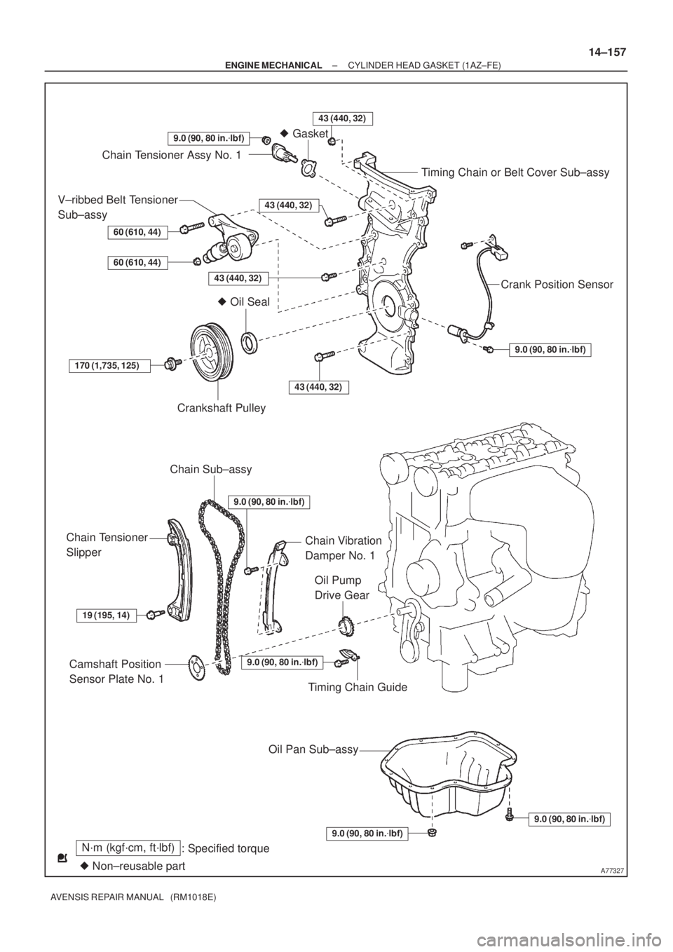
A77327
N´m (kgf´cm, ft´lbf)
: Specified torque
� Non±reusable part� Gasket
9.0 (90, 80 in.�lbf)
Chain Tensioner Assy No. 1
Timing Chain or Belt Cover Sub±assy
Crank Position Sensor
9.0 (90, 80 in.�lbf)
V±ribbed Belt Tensioner
Sub±assy
60 (610, 44)
60 (610, 44)
43 (440, 32)
170 (1,735, 125)
Crankshaft Pulley
Chain Sub±assy
43 (440, 32)
Chain Tensioner
Slipper
19 (195, 14)
Camshaft Position
Sensor Plate No. 1
Oil Pump
Drive Gear
Chain Vibration
Damper No. 1
� Oil Seal
Timing Chain Guide
9.0 (90, 80 in.�lbf)
Oil Pan Sub±assy
9.0 (90, 80 in.�lbf)
9.0 (90, 80 in.�lbf)
43 (440, 32)
43 (440, 32)
9.0 (90, 80 in.�lbf)
± ENGINE MECHANICALCYLINDER HEAD GASKET (1AZ±FE)
14±157
AVENSIS REPAIR MANUAL (RM1018E)
Page 2164 of 5135
A77286
Push
A64641
A00019
A77288
± ENGINE MECHANICALCHAIN SUB±ASSY (1AZ±FE)
14±143
AVENSIS REPAIR MANUAL (RM1018E)
26. REMOVE CHAIN TENSIONER ASSY NO.1
(a) Remove the 2 nuts, the chain tensioner No. 1 and gasket.
NOTICE:
Do not turn the crankshaft.
27. REMOVE CRANKSHAFT POSITION SENSOR
28. REMOVE OIL PAN SUB±ASSY
(a) Remove the 12 bolts and 2 nuts.
(b) Insert the blade of SST between the crank case, timing
chain cover and oil pan, cut off applied sealer and remove
the oil pan.
SST 09032±00100
NOTICE:
Be careful not to damage the contact surface of the timing
chain cover, crank case and oil pan.
29. REMOVE V±RIBBED BELT TENSIONER ASSY
Page 2165 of 5135
A77289
Pry
A77243
14±144
± ENGINE MECHANICALCHAIN SUB±ASSY (1AZ±FE)
AVENSIS REPAIR MANUAL (RM1018E)
30. REMOVE TIMING CHAIN OR BELT COVER
SUB±ASSY
(a) Remove the 14 bolts and 2 nuts.
(b) Using a screwdriver, pry between the timing chain cover
and cylinder head or cylinder block.
(c) Remove the timing chain cover.
NOTICE:
Be careful not to damage the contact surface of the timing
chain cover, cylinder head and cylinder block.
31. REMOVE CRANKSHAFT POSITION SENSOR PLATE NO.1
32. REMOVE CHAIN TENSIONER SLIPPER
(a) Remove the 2 bolts and the chain tensioner slipper.
33. REMOVE CHAIN VIBRATION DAMPER NO.1
(a) Remove the bolt and the chain vibration damper No. 1
34. REMOVE TIMING CHAIN GUIDE
(a) Remove the bolt and the timing chain guide.
35. REMOVE CHAIN SUB±ASSY
36. REMOVE CRANKSHAFT TIMING GEAR OR SPROCKET
Page 2169 of 5135

AVENSIS REPAIR MANUAL (RM1018E)
(a) Align the mark links")
A77389
Timing MarksMark Links
Timing Mark
A77290
Hold
Stopper
A32629
A77390Seal Packing 14±148
± ENGINE MECHANICALCHAIN SUB±ASSY (1AZ±FE)
AVENSIS REPAIR MANUAL (RM1018E)
(a) Align the mark links (gold or yellow colored links) with
each timing mark located on the camshaft timing gears,
and install the chain.
43. INSTALL TIMING CHAIN GUIDE
Torque: 9.0 N�m (92 kgf�cm, 80 in.�lbf)
44. INSTALL CHAIN TENSIONER SLIPPER
(a) Install the chain tensioner slipper with the bolt.
Torque: 19 N�m (195 kgf�cm, 14 ft�lbf)
(b) Check that the chain tensioner slipper is hold on the cylin-
der block stopper.
45. INSTALL CRANKSHAFT POSITION SENSOR PLATE
NO.1
(a) Install the plate with the ºFº mark facing forward.
46. INSTALL TIMING CHAIN OR BELT COVER SUB±ASSY
NOTICE:
�Remove any oil from the contact surface.
�Install the chain cover within 3 minutes after applying
seal packing.
�Do not start the engine within 2 hours after installing.
(a) Remove any old packing (FIPG) material and be careful
not to drop any oil on the contact surfaces of the timing
chain cover.
(b) Apply a continuous bead (Diameter 2 mm (0.09 in.)) of
seal packing as shown in the illustration.
Seal packing: Part No. 08826 ± 00080 or equivalent.
Page 2171 of 5135

AVENSIS REPAIR MANUAL (RM1018E)
48. INSTALL OIL PAN SUB±ASSY
NOTICE:
�Remove")
A77392
Seal Packing6mm
A64641
A77393
SST
A77394
Raise
PinHook
Push 14±150
± ENGINE MECHANICALCHAIN SUB±ASSY (1AZ±FE)
AVENSIS REPAIR MANUAL (RM1018E)
48. INSTALL OIL PAN SUB±ASSY
NOTICE:
�Remove any oil from the contact surface.
�Install the oil pan within 3 minutes after applying seal
packing.
�Do not start the engine within 2 hours after installing.
(a) Remove any old packing (FIPG) material and be careful
not to drop any oil on the contact surface of the cylinder
block and oil pan.
(b) Apply a continuous bead (Diameter 3 mm to 4 mm (0.157
in.)) of seal packing as shown in the illustration, and install
the oil pan.
Seal packing: part No. 08826 ± 00080 or equivalent
(c) Install the oil pan with the 12 bolts and 2 nuts.
Torque: 9.0 N�m (92 kgf�cm, 80 in.�lbf)
49. INSTALL CRANKSHAFT POSITION SENSOR
50. INSTALL CRANKSHAFT PULLEY
(a) Using SST, tighten the set bolt.
SST 09213±54015 (91651±60855), 09330±00021
Torque: 170 N�m (1,733 kgf�cm, 125 ft�lbf)
51. INSTALL CHAIN TENSIONER ASSY NO.1
(a) Release the ratchet pawl, fully push in the plunger and ap-
ply the hook to the pin so that the plunger is located in
position.

14±163
AVENSIS REPAIR MANUAL (RM1018E)
45.REMOVE THROTTLE BODY ASSY (See page 10±26)
46.REMOVE INTAKE MANIFOLD
(a)Remove the")

14±143
AVENSIS REPAIR MANUAL (RM1018E)
26. REMOVE CHAIN TENSIONER ASSY NO.1
(a) Remove the 2 nuts, the chain tensioner")

AVENSIS REPAIR MANUAL (RM1018E)
30. REMOVE TIMING CHAIN OR BELT COVER
SUB±ASSY
(a) Remove the 14 bolts and 2 nuts.
(b) Using")