Page 2279 of 5135
1509S±01
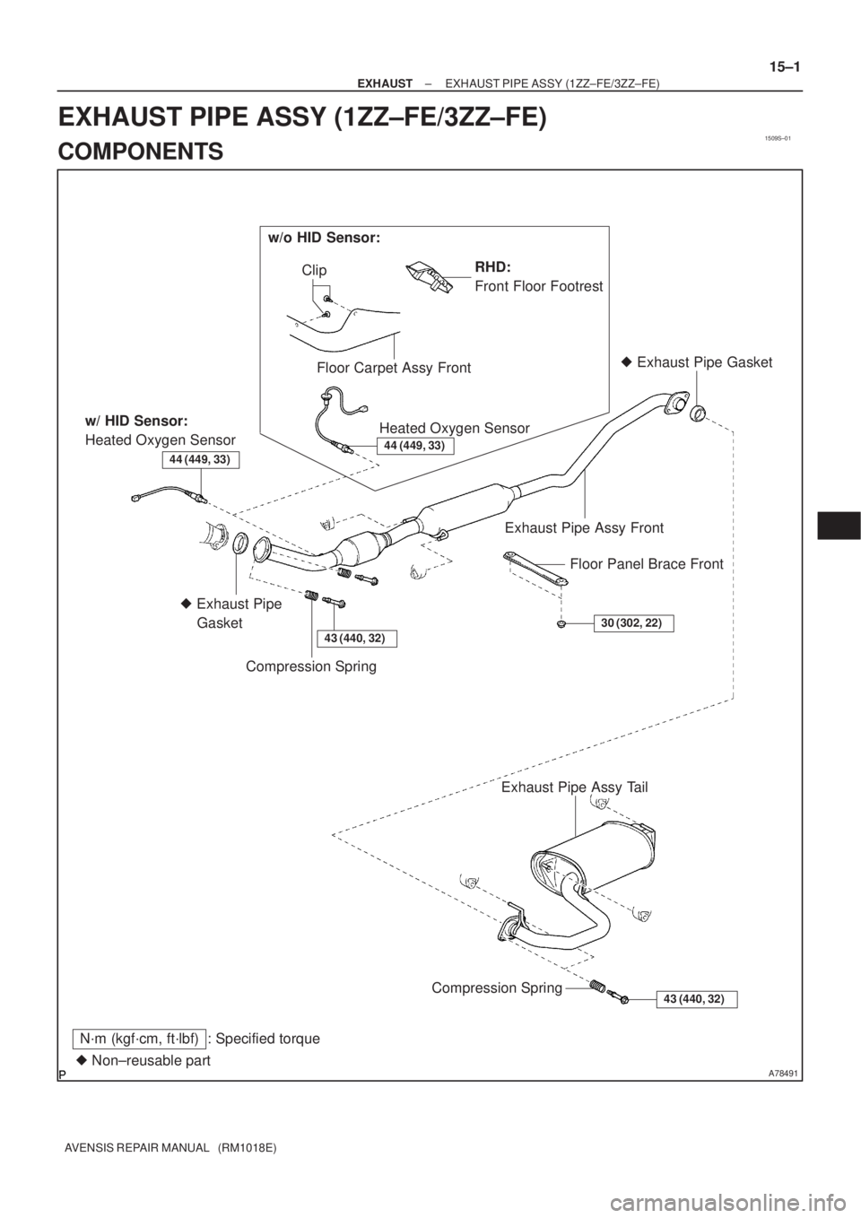
A78491� Non±reusable part
N´m (kgf´cm, ft´lbf) : Specified torqueExhaust Pipe Assy Front
Compression SpringFloor Panel Brace Front
� Exhaust Pipe
Gasket
43 (440, 32)
� Exhaust Pipe Gasket
30 (302, 22)
43 (440, 32)Compression Spring
Exhaust Pipe Assy Tail
w/ HID Sensor:
Heated Oxygen Sensor
44 (449, 33)44 (449, 33)
RHD:
Front Floor Footrest Clip
Floor Carpet Assy Front
Heated Oxygen Sensor
w/o HID Sensor:
± EXHAUSTEXHAUST PIPE ASSY (1ZZ±FE/3ZZ±FE)
15±1
AVENSIS REPAIR MANUAL (RM1018E)
EXHAUST PIPE ASSY (1ZZ±FE/3ZZ±FE)
COMPONENTS
Page 2283 of 5135

14±343
AVENSIS REPAIR MANUAL (RM1018E)
20.REMOVE TIMING BELT(See page 14±")
SST
A09582
B07973
Cut PositionPry
SST
A08528
SST
A09583
Angle
SensorInward
±
ENGINE MECHANICAL CRANKSHAFT SEAL(1CD±FTV)
14±343
AVENSIS REPAIR MANUAL (RM1018E)
20.REMOVE TIMING BELT(See page 14±307)
21.REMOVE CRANKSHAFT TIMING PULLEY
(a)If the timing pulley cannot be removed by hand, use SSTto remove the pulley.
SST09950±50013 (09951±05010, 09952±05010, 09953±05010, 09953±05020, 09954±05021)
22.REMOVE CRANKSHAFT SEAL
(a)Using a knife, cut off the oil seal lip.
(b)Using a screwdriver, pry out the oil seal.
NOTICE:
Be careful not to damage the crankshaft. Warp tip of the
screwdriver with tape.
23.INSTALL CRANKSHAFT SEAL
(a)Using SST and a hammer, tap in the oil seal until its sur- face is flush with the oil pump edge.
SST09316±60011 (09316±00011)
24.INSTALL CRANKSHAFT TIMING PULLEY
(a)Align the keyway of the timing pulley with the key located on the crankshaft, slide the pulley into place.
(b)Using SST and a hammer, tap in the timing pulley with the angle sensor facing inward.
SST09223±46011
25.SET NO. 1 CYLINDER TO TDC/COMPRESSION(See page 14±307) SST 09960±10010 (09962±01000, 09963±01000)
26.INSTALL TIMING BELT(See page 14±307)
27.CHECK VALVE TIMING(See page 14±307)
28.INSTALL TIMING CHAIN COVER PLATE(See page 14±307)
Page 2286 of 5135

14±333
AVENSIS REPAIR MANUAL (RM1018E)
42.REMOVE EXHAUST MANIFOLD HEAT INSULATOR NO.2 (See page 13±11)
43.REMOVE MANIFOLD")
A79148
SST
A79143
SST
±
ENGINE MECHANICAL CYLINDER HEAD GASKET (1CD±FTV)
14±333
AVENSIS REPAIR MANUAL (RM1018E)
42.REMOVE EXHAUST MANIFOLD HEAT INSULATOR NO.2 (See page 13±11)
43.REMOVE MANIFOLD STAY NO.2 (See page 13±11)
44.REMOVE MANIFOLD STAY (See page 13±11)
45.REMOVE EXHAUST MANIFOLD CONVERTER SUB±ASSY (See page 13±11)
46.REMOVE TURBOCHARGER STAY (See page 13±11)
47.REMOVE TURBO WATER HOSE NO.1 (See page 13±11)
48.REMOVE TURBO WATER HOSE NO.2 (See page 13±11)
49.SEPARATE TURBO OIL INLET PIPE SUB±ASSY (See page 13±11)
50.REMOVE TURBOCHARGER SUB±ASSY (See page 13±11)
51.REMOVE CAMSHAFT POSITION SENSOR (See page 10±63)
52.REMOVE CAMSHAFT TIMING PULLEY (See page 14±318)
SST 09960±10010 (09962±01000, 09963±01000)
53. REMOVE FUEL INLET PIPE SUB±ASSY
(a) Using SST, remove the fuel inlet pipe from the commonrail side.
SST 09023±12700
(b) Using SST, remove the fuel inlet pipe from the pump side.
SST 09023±12700
NOTICE:
After removing the fuel pipe, cover the common rail and the
injector mounting holes with vinyl tape to prevent dust
from being introduced.
54. REMOVE INJECTION PIPE SUB±ASSY NO.1 (See page 11±60)
SST 09023±12700
(a) Remove the 2 nuts and 2 upper infection pipe clamps
from the intake manifold.
(b) Using SST, remove the injection pipe from the common rail side.
SST 09023±12700
(c) Using SST, remove the injection pipe from the injector
side.
SST 09023±12700
(d) After removing the fuel pipe, to prevent dust or foreign ob- jects from being introduced, cover the common rail with
vinyl tape and protect the injector inlet with a vinyl or a
plastic bag.
55. REMOVE INJECTION PIPE SUB±ASSY NO.2 SST 09023±12700
HINT:
Perform the same procedures as injection pipe No. 1.
56. REMOVE INJECTION PIPE SUB±ASSY NO.3
SST 09023±12700
HINT:
Perform the same procedures as injection pipe No. 1.
Page 2291 of 5135

AVENSIS REPAIR MANUAL (RM1018E)
76.INSTALL CAMSHAFT OIL SEAL RETAINER (See page 14±318)
77.INSTALL CAMSHAFT TIMING P")
A09663
:Seal Packing
14±338
±
ENGINE MECHANICAL CYLINDER HEAD GASKET(1CD±FTV)
AVENSIS REPAIR MANUAL (RM1018E)
76.INSTALL CAMSHAFT OIL SEAL RETAINER (See page 14±318)
77.INSTALL CAMSHAFT TIMING PULLEY (See page 14±318) SST 09960±10010 (09962±01000, 09963±01000)
78.INSTALL CAMSHAFT POSITION SENSOR (See page 10±64)
79.INSTALL INJECTOR ASSY(See page 11±60)
80.INSTALL NOZZLE LEAKAGE PIPE ASSY(See page 11±60) SST 09992±00242
81. INSTALL CYLINDER HEAD COVER SUB±ASSY
(a) Remove any old packing (FIPG) material.
(b) Apply seal packing to the cylinder head.Seal packing: Part No. 08826±00080 or equivalent
(c) Install the gasket to the head cover.
(d) Install the cylinder head cover with the 10 bolts. Torque: 13 N �m (135 kgf �cm, 9.7 ft �lbf)
82. INSTALL NOZZLE HOLDER SEAL
(a) Install 4 new nozzle holder seals.
83.INSTALL VACUUM PUMP ASSY (See page 14±318) 84. INSTALL INJECTION PIPE SUB±ASSY NO.1(See page 11±60)
NOTICE:
When assembling the pipes, perform the operation with the
engine cold under room temperature.
(a) Remove the vinyl or the plastic bag from the injector and vinyl tape from the common rail.
(b) Temporarily install the injection pipe.
Page 2299 of 5135
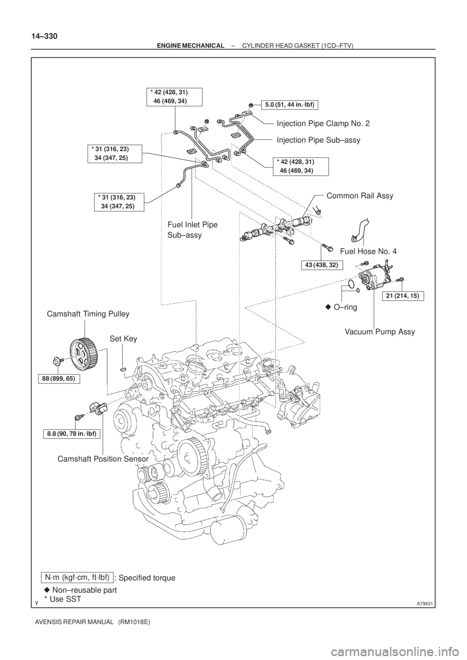
A79431
N´m (kgf´cm, ft´lbf)
: Specified torque
� Non±reusable part
* Use SST
5.0 (51, 44 in.�lbf)
* 31 (316, 23)
34 (347, 25)
* 31 (316, 23)
34 (347, 25)
Injection Pipe Clamp No. 2
Injection Pipe Sub±assy
* 42 (428, 31)
46 (469, 34)
Fuel Inlet Pipe
Sub±assy
� O±ring
43 (438, 32)
21 (214, 15)
Common Rail Assy
Fuel Hose No. 4
Camshaft Position Sensor
Set Key Camshaft Timing Pulley
88 (899, 65)
Vacuum Pump Assy
8.8 (90, 78 in.�lbf)
* 42 (428, 31)
46 (469, 34)
14±330
± ENGINE MECHANICALCYLINDER HEAD GASKET (1CD±FTV)
AVENSIS REPAIR MANUAL (RM1018E)
Page 2301 of 5135

AVENSIS REPAIR MANUAL (RM1018E)
REPLACEMENT
1.REMOVE FRONT WHEEL RH
2.REMOVE ENGINE UNDER COVER SUB±ASSY NO.1
3.ENGINE UNDER COVE")
141C8±01
SSTA61187
14±318
±
ENGINE MECHANICAL CAMSHAFT(1CD±FTV)
AVENSIS REPAIR MANUAL (RM1018E)
REPLACEMENT
1.REMOVE FRONT WHEEL RH
2.REMOVE ENGINE UNDER COVER SUB±ASSY NO.1
3.ENGINE UNDER COVER RH
4.REMOVE RADIATOR SUPPORT OPENING COVER
5.REMOVE ENGINE ROOM COVER SIDE
6.REMOVE ENGINE COVER NO.1
(a)Remove the 5 nuts and the engine cover.
7.REMOVE AIR CLEANER ASSY (See page 11±60)
8.REMOVE VACUUM RESERVOIR SUB±ASSY
(a)Disconnect the 2 vacuum hoses and the connector.
(b)Remove the 2 bolts and the vacuum reservoir.
9.REMOVE AIR TUBE NO.1 (See page 14±270)
10.REMOVE INJECTOR DRIVER (See page 14±286)
11. REMOVE V (COOLER COMPRESSOR TO CRANKSHAFT PULLEY) BELT NO.1 (See page 14±269)
12.REMOVE GENERATOR V BELT (See page 14±269)
13.SEPARATE POWER STEERING IDLE PULLEY BRACKET (See page 14±286)
14.REMOVE ENGINE MOUNTING INSULATOR SUB±ASSY RH (See page 14±307)
15.REMOVE CRANKSHAFT PULLEY (See page 14±307) SST 09213±54015 (90105±08076), 09330±00021, 09950±50013 (0995\
1±05010, 09952±05010, 09953±05020, 09954±05031)
16.REMOVE IDLER PULLEY SUB±ASSY (See page 14±307)
17.REMOVE TIMING BELT NO.2 COVER (See page 14±307)
18.REMOVE TIMING BELT NO.1 COVER (See page 14±307)
19. REMOVE TIMING BELT GUIDE
20.REMOVE TRANSVERSE ENGINE ENGINE MOUNTING BRACKET (See page 14±307)
21.SET NO. 1 CYLINDER TO TDC/COMPRESSION (See page 14±307)
22.REMOVE TIMING CHAIN COVER PLATE (See page 14±307)
23.REMOVE TIMING BELT (See page 14±307)
24.REMOVE CAMSHAFT POSITION SENSOR (See page 10±63)
25. REMOVE CAMSHAFT TIMING PULLEY
(a) Using SST, remove the pulley bolt.SST 09960±10010 (09962±01000, 09963±01000)
(b) Remove the timing pulley.
HINT:
Using a plastic±faced hammer, tap out the pulley.
(c) Remove the set key.
Page 2306 of 5135

14±323
AVENSIS REPAIR MANUAL (RM1018E)
(c)Install the oil seal retainer with the 4 bolts. Tighten the 4
bolts uniformly in se")
A62592
SST
A09663
:Seal Packing
±
ENGINE MECHANICAL CAMSHAFT(1CD±FTV)
14±323
AVENSIS REPAIR MANUAL (RM1018E)
(c)Install the oil seal retainer with the 4 bolts. Tighten the 4
bolts uniformly in several steps.
Torque: 8.8 N �m (90 kgf �cm, 78 in. �lbf)
46.INSTALL CAMSHAFT TIMING PULLEY
(a)Install the pulley set key to the groove of the camshaft.
(b)Align the keyway of the timing pulley with the key located on the camshaft, slide the pulley into place.
(c)Using SST, install the pulley bolt. SST09960±10010 (09962±01000, 09963±01000)
Torque: 88 N �m (899 kgf �cm, 65 ft �lbf)
47.INSTALL CAMSHAFT POSITION SENSOR (See page 10±63)
48.INSTALL INJECTOR ASSY (See page 11±60)
49.INSTALL NOZZLE LEAKAGE PIPE ASSY(See page 11±60) SST09992±00242
50.INSTALL CYLINDER HEAD COVER SUB±ASSY
(a)Remove any old packing (FIPG) material.
(b)Apply seal packing to the cylinder head.Seal packing: Part No. 08826±00080 or equivalent
(c)Install the gasket to the cylinder head cover.
(d)Install the cylinder head cover with the 10 bolts.
Torque: 13 N �m (135 kgf �cm, 9.7 ft �lbf)
51.INSTALL NOZZLE HOLDER SEAL
(a)Install 4 new nozzle holder seals.
52.INSTALL VACUUM PUMP ASSY Torque: 21 N �m (214 kgf �cm,15 ft �lbf)
53.INSTALL INJECTION PIPE SUB±ASSY NO.1 (See page 11±60)
NOTICE:
When assembling the pipes, perform the operation with the
engine cold under room temperature.
(a) Remove the vinyl or the plastic bag from the injector and vinyl tape from the common rail.
(b) Temporarily install the injection pipe.
Page 2324 of 5135

AVENSIS REPAIR MANUAL (RM1018E)
34.SEPARATE RETURN TUBE SUB±ASSY
(a)Remove the 2 clamp bolts and separate the return tube su")
A79140
A79184
14±288
±
ENGINE MECHANICAL PARTIAL ENGINE ASSY(1CD±FTV)
AVENSIS REPAIR MANUAL (RM1018E)
34.SEPARATE RETURN TUBE SUB±ASSY
(a)Remove the 2 clamp bolts and separate the return tube sub±assy.
35.SEPARATE VANE PUMP OIL RESERVOIR ASSY
36.REMOVE FRONT AXLE HUB LH NUT (See page 30±6) SST09930±00010
HINT:
Perform the same procedure as above on the opposite side.
37.SEPARATE TIE ROD END SUB±ASSY LH (See page 30±6) SST 09628±62011
HINT:
Perform the same procedure as above on the opposite side.
38.SEPARATE FRONT STABILIZER LINK ASSY LH (See page 26±26)
HINT:
Perform the same procedure as above on the opposite side.
39. REMOVE COLUMN HOLE COVER SILENCER SHEET
(a) Remove the 2 clips and the column hole cover silencer sheet.
40.REMOVE STEERING INTERMEDIATE SHAFT ASSY NO.2 (See page 51±36)
41.SEPARATE FRONT SUSPENSION ARM SUB±ASSY LOWER NO.1 LH (See page 26±21)
HINT:
Perform the same procedure as above on the opposite side.
42.SEPARATE FRONT DRIVE SHAFT ASSY LH (See page 30±6)
HINT:
Perform the same procedure as above on the opposite side.
43. REMOVE ENGINE ASSEMBLY WITH TRANSAXLE
(a) Disconnect the height control sensor connector (w/ Dis-charge head lamp).