Page 2388 of 5135

16±29
AVENSIS REPAIR MANUAL (RM1018E)
COOLING FAN SYSTEM (1AZ±FSE)
ON±VEHICLE INSPECTION
HINT:
It is normal that the cooling fan sometime rotates")
1600R±12
± COOLINGCOOLING FAN SYSTEM (1AZ±FSE)
16±29
AVENSIS REPAIR MANUAL (RM1018E)
COOLING FAN SYSTEM (1AZ±FSE)
ON±VEHICLE INSPECTION
HINT:
It is normal that the cooling fan sometime rotates when the ignition switch is turned from ACC to ON.
1. CHECK COOLING FAN OPERATION WITH LOW TEMPERATURE (Below 83�C (181�F))
(a) Turn the ignition switch ON.
(b) Check that the cooling fan stops.
If not, check the cooling fan relay and engine coolant temperature sensor, and check for disconnection of
connectors or wire break between the cooling fan relay and engine coolant temperature sensor.
(c) Disconnect the engine coolant temperature sensor connector.
(d) Check that the cooling fan rotates.
If not, check the fuses, cooling fan relay, ECM and cooling fan, and check for a short circuit between the
cooling fan relay and engine coolant temperature sensor.
(e) Reconnect the engine coolant temperature sensor connector.
2. CHECK COOLING FAN OPERATION WITH HIGH TEMPERATURE (Above 100�C (212�F))
(a) Start the engine, and raise coolant temperature to above 100�C (212�F).
HINT:
Coolant temperature is the detected value by the engine coolant temperature sensor on the water outlet.
(b) Check that the cooling fan rotates.
If not, replace the engine coolant temperature sensor.
3. INSPECT COOLING FAN
(a) Disconnect the cooling fan connector.
(b) Connect battery and ammeter to the cooling fan connector.
(c) Check that the cooling fan rotates smoothly, and check the reading on the ammeter.
Standard amperage:
5.2 to 8.2 A at 20�C (68�F) (M/T)
8.3 to 11.3 A at 20�C (68�F) (A/T)
(d) Reconnect the cooling fan connector.
4. INSPECT COOLING FAN No.2 (With Air Conditioner)
(a) Disconnect the cooling fan connector.
(b) Connect battery and ammeter to the cooling fan connector.
(c) Check that the cooling fan rotates smoothly, and check the reading on the ammeter.
Standard amperage:
5.2 to 8.2 A at 20�C (68�F) (M/T)
8.3 to 11.3 A at 20�C (68�F) (A/T)
(d) Reconnect the cooling fan connector.
Page 2395 of 5135
160MW±01
B12054
SST
B12052
B12053
Pry
PryPry
±
COOLING WATER PUMP ASSY(1AZ±FE)
16±21
AVENSIS REPAIR MANUAL (RM1018E)
WATER PUMP ASSY(1AZ±FE)
REPLACEMENT
1.DRAIN COOLANT (See page 16±19)
2. REMOVE RADIATOR SUPPORT OPENING COVER
3. REMOVE ENGINE ROOM COVER SIDE
4. REMOVE ENGINE UNDER COVER RH
5.REMOVE FAN AND GENERATOR V BELT (See page 14±105)
SST 09249±63010
6.REMOVE GENERATOR ASSY (See page 19±20)
7. REMOVE WATER PUMP PULLEY
(a) Using SST, remove 4 bolts and pump pulley.SST 09960±10010 (09962±01000, 09963±00700)
(b) Disconnect the crankshaft position sensor wire clamp from the water pump.
(c) Disconnect the crankshaft position sensor wire from the clamp on the water pump.
8. REMOVE WATER PUMP ASSY
(a) Remove 4 bolts, 2 nuts, wire clamp and water pump.
(b) Using a screwdriver, pry between the water pump and cyl- inder block, and remove the water pump.
NOTICE:
Be careful not to damage the contact surface of the water
pump and cylinder block.
Page 2396 of 5135

AVENSIS REPAIR MANUAL (RM1018E)
9.INSTALL WATER PUMP ASSY
(a)Remove any old packing (FIPG)")
A57664
Seal Width
2.2 to 2.5 mm0.5 to 1.0 mm
B12052
B12054
SST
16±22
±
COOLING WATER PUMP ASSY(1AZ±FE)
AVENSIS REPAIR MANUAL (RM1018E)
9.INSTALL WATER PUMP ASSY
(a)Remove any old packing (FIPG) material from the con- tact surface.
(b)Apply seal packing to the water pump as shown in the il- lustration.
Seal packing: Part No. 08826 ± 00100 or equivalent
�Install a nozzle that has been cut to a 2.2 to 2.5 mm
(0.09 to 0.10 in.) opening.
�Parts must be assembled within 5 minutes of ap-
plication. Otherwise the material must be removed
and reapplied.
�Immediately remove nozzle from the tube and rein-
stall cap.
(c)Install the water pump and wire clamp with 4 bolts and 2
nuts.
Torque: 9.0 N �m (90 kgf �cm, 80 in. �lbf)
(d)Install the crankshaft position sensor wire harness clamp to the water pump.
(e)Install the crankshaft position sensor wire to the wire clamp on the water pump.
10.INSTALL WATER PUMP PULLEY
(a)Using SST, install the pump pulley with 4 bolts. SST09960±10010 (09962±01000, 09963±00700)
Torque: 26 N �m (265 kgf �cm, 19 ft �lbf)
11.INSTALL GENERATOR ASSY (See page 19±20)
12.INSTALL FAN AND GENERATOR V BELT (See page 14±105) SST 09249±63010
13.ADD COOLANT (See page 16±19)
14.INSPECT CHECK FOR ENGINE COOLANT LEAKS (See page 16±17)
Page 2398 of 5135
A79173
A79174
A56695
A79175
A56696
± LUBRICATIONOIL PUMP ASSY (1CD±FTV)
17±23
AVENSIS REPAIR MANUAL (RM1018E)
27. REMOVE OIL LEVEL GAGE GUIDE
(a) Remove the bolt which is used to secure the oil level gage
guide to the cylinder block.
(b) Pull out the oil level gage guide together with the oil level
gage from the No. 1 oil pan.
(c) Remove the O±ring from the oil level gage guide.
28. REMOVE ENGINE OIL LEVEL SENSOR
(a) Remove the 4 bolts and the level sensor.
NOTICE:
Be careful not to drop the oil level sensor when removing.
29. REMOVE OIL PAN SUB±ASSY NO.2
(a) Remove the 17 bolts and 2 nuts.
(b) Insert the blade of SST between the No. 1 and No. 2 oil
pans, and cut off applied sealer and remove the No. 2 oil
pan.
SST 09032±00100
NOTICE:
Be careful not to damage the No. 1 and No. 2 oil pans.
30. REMOVE OIL STRAINER SUB±ASSY
(a) Remove the 2 bolts and 2 nuts, then remove the oil strain-
er and the gasket.
Page 2399 of 5135
B08009
A56697
A56698
A56699
17±24
± LUBRICATIONOIL PUMP ASSY (1CD±FTV)
AVENSIS REPAIR MANUAL (RM1018E)
31. REMOVE OIL PAN INSULATOR
(a) Remove the bolt and the oil pan insulator.
32. REMOVE OIL PAN SUB±ASSY
(a) Remove the 19 bolts and 3 nuts.
(b) Using a screwdriver, remove the oil pan by prying be-
tween the cylinder block and the No. 1 oil pan.
NOTICE:
Be careful not to damage the cylinder block and No. 1 oil
pan.
33. REMOVE CRANKSHAFT POSITION SENSOR
34. REMOVE OIL PUMP ASSY
(a) Remove the 9 bolts.
(b) Remove the oil pump by prying between the oil pump and
the main bearing cap with a screwdriver.
(c) Remove the gasket.
Page 2401 of 5135
A57099
A56702
17±26
± LUBRICATIONOIL PUMP ASSY (1CD±FTV)
AVENSIS REPAIR MANUAL (RM1018E)
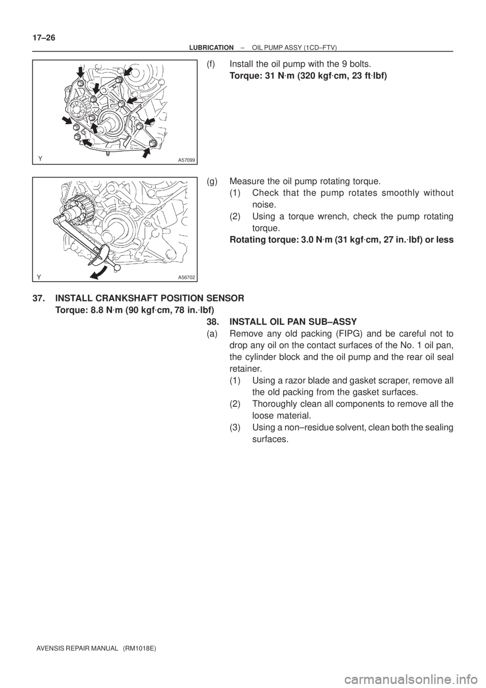
(f) Install the oil pump with the 9 bolts.
Torque: 31 N�m (320 kgf�cm, 23 ft�lbf)
(g) Measure the oil pump rotating torque.
(1) Check that the pump rotates smoothly without
noise.
(2) Using a torque wrench, check the pump rotating
torque.
Rotating torque: 3.0 N�m (31 kgf�cm, 27 in.�lbf) or less
37. INSTALL CRANKSHAFT POSITION SENSOR
Torque: 8.8 N�m (90 kgf�cm, 78 in.�lbf)
38. INSTALL OIL PAN SUB±ASSY
(a) Remove any old packing (FIPG) and be careful not to
drop any oil on the contact surfaces of the No. 1 oil pan,
the cylinder block and the oil pump and the rear oil seal
retainer.
(1) Using a razor blade and gasket scraper, remove all
the old packing from the gasket surfaces.
(2) Thoroughly clean all components to remove all the
loose material.
(3) Using a non±residue solvent, clean both the sealing
surfaces.
Page 2403 of 5135

AVENSIS REPAIR MANUAL (RM1018E)
(3)Using a non±residue solvent, clean both the sealing surfaces.")
A56704
Seal Width
4 to 7 mm
A
B B
A
A79173New O±ring
17±28
±
LUBRICATION OIL PUMP ASSY(1CD±FTV)
AVENSIS REPAIR MANUAL (RM1018E)
(3)Using a non±residue solvent, clean both the sealing surfaces.
NOTICE:
Do not use a solvent, which will affect the painted surfaces.
(b)Apply a seal packing to the oil pan as shown in the illustra- tion.
Seal packing: Part No. 08826±00080 or equivalent
(1)Install a nozzle that has been cut to a 4 to 7 mm
(0.16 to 0.28 in.) opening.
(2)Parts must be set within 3 minutes and assembled within 15 minutes of application. Otherwise the ma-
terial must be removed and reapplied.
(3)Immediately remove nozzle from the tube and rein- stall the cap.
(c)Install the oil pan with the 17 bolts and 2 nuts. Tighten the
bolts and nuts uniformly in several steps.
Torque: 12 N �m (119 kgf �cm, 9ft �lbf)
42.INSTALL ENGINE OIL LEVEL SENSOR Torque: 7.0 N �m (71 kgf �cm, 62 in. �lbf)
43.INSTALL OIL LEVEL GAGE GUIDE
(a)Install a new O±ring to the oil level gage guide.
(b)Apply engine oil to the O±ring.
(c)Push in the oil level gage guide end into the guide hole of the No. 1 oil pan.
(d)Install the oil level gage guide with the bolt. Torque: 18 N �m (184 kgf �cm, 13 ft �lbf)
(e)Apply engine oil to the O±ring on the oil level gage.
(f)Install the oil level gage.
44.INSTALL V±RIBBED BELT TENSIONER ASSY Torque: 31 N �m (320 kgf �cm,23 ft �lbf)
45.INSTALL TIMING BELT IDLER SUB±ASSY NO.1
Torque: 35 N �m (357 kgf �cm,26 ft �lbf)
46.INSTALL GENERATOR ASSY(See page 19±29)
Page 2404 of 5135

17±29
AVENSIS REPAIR MANUAL (RM1018E)
47.INSTALL CRANKSHAFT TIMING PULLEY
(a)Align the keyway of the timing pulley with the key")
SST
A09583
Inward
Angle Sensor
±
LUBRICATION OIL PUMP ASSY(1CD±FTV)
17±29
AVENSIS REPAIR MANUAL (RM1018E)
47.INSTALL CRANKSHAFT TIMING PULLEY
(a)Align the keyway of the timing pulley with the key located
on the camshaft, slide the pulley into place.
(b)Using SST and a hammer, tap in the timing pulley with the angle sensor facing inward.
SST09223±46011
48.INSTALL TIMING BELT IDLER SUB±ASSY NO.2 Torque: 47 N �m (479 kgf �cm,35 ft �lbf)
49.SET NO. 1 CYLINDER TO TDC/COMPRESSION(See page 14±307) SST 09960±10010 (09962±01000, 09963±01000)
50.INSTALL TIMING BELT(See page 14±307)
51.CHECK VALVE TIMING(See page 14±307)
52.INSTALL TIMING CHAIN COVER PLATE(See page 14±307)
53.INSTALL TRANSVERSE ENGINE ENGINE MOUNTING BRACKET(See page 14±307)
54.INSTALL TIMING BELT GUIDE(See page 14±307)
55.INSTALL TIMING BELT NO.1 COVER(See page 14±307)
56.INSTALL TIMING BELT NO.2 COVER(See page 14±307)
57.INSTALL CRANKSHAFT PULLEY(See page 14±307) SST 09213±54015 (90105±08076), 09330±00021
58. INSTALL ENGINE MOUNTING INSULATOR SUB±ASSY RH Torque: 52 N �m (530 kgf �cm, 38 ft �lbf)
59. INSTALL IDLER PULLEY SUB±ASSY
60.INSTALL POWER STEERING IDLE PULLEY BRACKET (See page 14±286)
61. ADJUST V (COOLER COMPRESSOR TO CRANKSHAFT PULLEY) BELT NO.1 (See page 14±269)
62.INSTALL INJECTOR DRIVER (See page 14±307)
63. INSTALL ENGINE COVER NO.1 Torque: 8.0 N �m (82 kgf �cm, 71 in. �lbf)
64. INSTALL FRONT WHEEL RH Torque: 103 N �m (1,050 kgf �cm, 76 ft �lbf)
65.ADD ENGINE OIL(See page 17±30)
66. CHECK FOR ENGINE OIL LEAKS

16±21
AVENSIS REPAIR MANUAL (RM1018E)
WATER PUMP ASSY(1AZ±FE)
REPLACEMENT
1.DRAIN COOLANT (See page 16±19)
2. REM")

17±23
AVENSIS REPAIR MANUAL (RM1018E)
27. REMOVE OIL LEVEL GAGE GUIDE
(a) Remove the bolt which is used to secure the oil l")

AVENSIS REPAIR MANUAL (RM1018E)
31. REMOVE OIL PAN INSULATOR
(a) Remove the bolt and the oil pan insulator.
32. REMOVE OIL P")