Page 2331 of 5135

A79173New O±Ring
±
ENGINE MECHANICAL PARTIAL ENGINE ASSY(1CD±FTV)
14±295
AVENSIS REPAIR MANUAL (RM1018E)
106.REMOVE CRANKSHAFT POSITION SENSOR
(a)Remove the bolt and the crankshaft position sensor.
107.REMOVE CAMSHAFT POSITION SENSOR
(a)Remove the bolt and the camshaft position sensor.
108.REMOVE ENGINE COOLANT TEMPERATURE SENSOR
109.REPLACE PARTIAL ENGINE ASSY
110.INSTALL ENGINE COOLANT TEMPERATURE SENSOR
Torque: 20 N �m (204 kgf �cm,15 ft �lbf)
111.INSTALL CAMSHAFT POSITION SENSOR Torque: 8.8 N �m (90 kgf �cm,78 in. �lbf)
112.INSTALL CRANKSHAFT POSITION SENSOR Torque: 8.8 N �m (90 kgf �cm,78 in. �lbf)
113.INSTALL FUEL FILTER TO INJECTION PUMP FUEL PIPE Torque:
8.8 N�m (90 kgf �cm,78 ft �lbf) for M6 and Nut
21 N �m (209 kgf �cm,15 ft �lbf) for M8
114.INSTALL OIL COOLER PIPE
(a)Install 2 new gaskets and the oil cooler pipe with the union bolt. Torque: 59 N �m (600 kgf �cm,43 ft �lbf)
115.INSTALL THERMOSTAT (See page 16±50)
116.INSTALL WATER INLET (See page 16±50)
117. INSTALL COMPRESSOR MOUNTING BRACKET NO.1
Torque: 42 N �m (428 kgf �cm, 31 ft �lbf)
118. INSTALL INJECTION OR SUPPLY PUMP ASSY Torque: 21 N �m (214 kgf �cm, 15 ft �lbf)
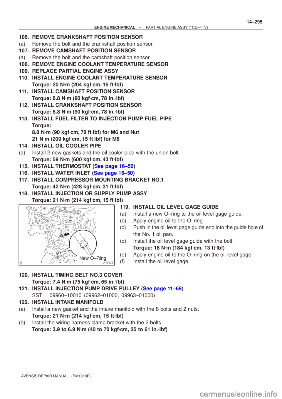
119. INSTALL OIL LEVEL GAGE GUIDE
(a) Install a new O±ring to the oil level gage guide.
(b) Apply engine oil to the O±ring.
(c) Push in the oil level gage guide end into the guide hole of the No. 1 oil pan.
(d) Install the oil level gage guide with the bolt. Torque: 18 N �m (184 kgf �cm, 13 ft �lbf)
(e) Apply engine oil to the O±ring on the oil level gage.
(f) Install the oil level gage.
120. INSTALL TIMING BELT NO.3 COVER Torque: 7.4 N �m (75 kgf �cm, 65 in. �lbf)
121.INSTALL INJECTION PUMP DRIVE PULLEY (See page 11±69)
SST 09960±10010 (09962±01000, 09963±01000)
122. INSTALL INTAKE MANIFOLD
(a) Install a new gasket and the intake manifold with the 8 bolts and 2 nuts\
. Torque: 21 N �m (214 kgf �cm, 15 ft �lbf)
(b) Install the wiring harness clamp bracket with the 2 bolts.
Torque: 3.9 to 6.9 N �m (40 to 70 kgf �cm, 35 to 61 in. �lbf)
Page 2340 of 5135
14±304
±
ENGINE MECHANICAL PARTIAL ENGINE ASSY (1CD±FTV)
AVENSIS REPAIR MANUAL (RM1018E)
191. INSTALL AIR CLEANER ASSY Torque: 7.0 N �m (71 kgf �cm, 62 in. �lbf)
192. INSTALL ENGINE COVER NO.1
Torque: 8.0 N �m (82 kgf �cm, 71 in. �lbf)
193.BLEED CLUTCH PIPE LINE (See page 42±17)
194. INSTALL FRONT WHEELS Torque: 103 N �m (1,050 kgf �cm, 76 ft �lbf)
195. ADD MANUAL TRANSAXLE OIL
196. ADD ENGINE OIL
197.ADD ENGINE COOLANT (See page 16±44)
198. CHECK CLUTCH FLUID LEAKAGE
199. CHECK FLUID LEVEL IN RESERVOIR
200. CHECK BRAKE FLUID LEAKAGE
201. CHECK FOR ENGINE OIL LEAKS
202.CHECK FOR FUEL LEAKS (See page 11±60)
203.CHECK FOR ENGINE COOLANT LEAKS (See page 16±44)
204. CHECK FOR EXHAUST GAS LEAKS
205.INSPECT AND ADJUST FRONT WHEEL ALIGNMENT (See page 26±6)
206.INSPECT ENGINE IDLE SPEED (See page 14±266)
207.CHECK ABS SPEED SENSOR SIGNAL (See page 05±756)
Page 2344 of 5135

1600R±13
± COOLINGCOOLING FAN SYSTEM (1AZ±FE)
16±17
AVENSIS REPAIR MANUAL (RM1018E)
COOLING FAN SYSTEM (1AZ±FE)
ON±VEHICLE INSPECTION
HINT:
It is normal that the cooling fan sometime rotates when the ignition switch is turned from ACC to ON.
1. CHECK COOLING FAN OPERATION WITH LOW TEMPERATURE (Below 77�C (171�F))
(a) Turn the ignition switch ON.
(b) Check that the cooling fan stops.
If not, check the cooling fan relay and engine coolant temperature sensor, and check for disconnection of
connectors or wire break between the cooling fan relay and engine coolant temperature sensor.
(c) Disconnect the engine coolant temperature sensor connector.
(d) Check that the cooling fan rotates.
If not, check the fuses, cooling fan relay, ECM and cooling fan, and check for a short circuit between the
cooling fan relay and engine coolant temperature sensor.
(e) Reconnect the engine coolant temperature sensor connector.
2. CHECK COOLING FAN OPERATION WITH HIGH TEMPERATURE (Above 95.5�C (204�F))
(a) Start the engine, and raise coolant temperature to above 95.5�C (204�F).
HINT:
Coolant temperature is the detected value by the engine coolant temperature sensor on the water outlet.
(b) Check that the cooling fan rotates.
If not, replace the engine coolant temperature sensor.
3. INSPECT COOLING FAN
(a) Disconnect the cooling fan connector.
(b) Connect battery and ammeter to the cooling fan connector.
(c) Check that the cooling fan rotates smoothly, and check the reading on the ammeter.
Standard amperage:
5.2 to 8.2 A at 20�C (68�F) (M/T)
8.3 to 11.3 A at 20�C (68�F) (A/T)
(d) Reconnect the cooling fan connector.
4. INSPECT COOLING FAN No.2 (With Air Conditioner)
(a) Disconnect the cooling fan connector.
(b) Connect battery and ammeter to the cooling fan connector.
(c) Check that the cooling fan rotates smoothly, and check the reading on the ammeter.
Standard amperage:
5.2 to 8.2 A at 20�C (68�F) (M/T)
8.3 to 11.3 A at 20�C (68�F) (A/T)
(d) Reconnect the cooling fan connector.
Page 2356 of 5135

1600R±14
± COOLINGCOOLING FAN SYSTEM (1ZZ±FE/3ZZ±FE)
16±5
AVENSIS REPAIR MANUAL (RM1018E)
COOLING FAN SYSTEM (1ZZ±FE/3ZZ±FE)
ON±VEHICLE INSPECTION
HINT:
It is normal that the cooling fan sometime rotates when the ignition switch is turned from ACC to ON.
1. CHECK COOLING FAN OPERATION WITH LOW TEMPERATURE (Below 94.5�C (202�F))
(a) Turn the ignition switch ON.
(b) Check that the cooling fan stops.
If not, check the cooling fan relay and engine coolant temperature sensor, and check if there is its connector
disconnection or circuit open between them.
(c) Disconnect the engine coolant temperature sensor connector.
(d) Check that the cooling fan rotates.
If not, check the fuses, cooling fan relay, ECM and cooling fan, and check for short in a circuit between the
cooling fan relay and the engine coolant temperature sensor.
(e) Reconnect the engine coolant temperature sensor connector.
2. CHECK COOLING FAN OPERATION WITH HIGH TEMPERATURE (Above 96�C (205�F))
(a) Start the engine, and raise coolant temperature to above 96�C (205�F).
HINT:
Coolant temperature is detected by the engine coolant temperature sensor on the water outlet.
(b) Check that the cooling fan rotates.
If not, replace the engine coolant temperature sensor.
3. INSPECT COOLING FAN
(a) Disconnect the cooling fan connector.
(b) Connect battery and ammeter to the connector.
(c) Check that the cooling fan rotates smoothly, and check the reading on the ammeter.
Standard amperage: Approximately. 8 to 12 A at 20�C (68�F)
(d) Reconnect the cooling fan connector.
Page 2368 of 5135
1509T±01
A78493
A78494
(c)
(d)
A78495
A78496
15±2
±
EXHAUST EXHAUST PIPE ASSY(1ZZ±FE/3ZZ±FE)
AVENSIS REPAIR MANUAL (RM1018E)
Removal & Installation and Disassembly & Reassembly
1.REMOVE FRONT FLOOR FOOTREST (W/O HID SENSOR) (See page 76±32) 2. REMOVE HEATED OXYGEN SENSOR (W/O HIDSENSOR)
(a) Using a clip remover, remove the 2 clips.
(b) Open the floor carpet.
(c) Disconnect the heated oxygen sensor connector.
(d) Remove the grommet.
(e) Remove the heated oxygen sensor.
3. REMOVE HEATED OXYGEN SENSOR (W/ HID SENSOR)
(a) Disconnect the heated oxygen sensor connector.
(b) Remove the heated oxygen sensor.
Page 2371 of 5135
A77857
A78440
New Gasket
± EXHAUSTEXHAUST PIPE ASSY (1ZZ±FE/3ZZ±FE)
15±5
AVENSIS REPAIR MANUAL (RM1018E)
8. INSTALL EXHAUST PIPE ASSY TAIL
(a) Compression spring inspection
(1) Using vernier calipers, measure the free length of
the compression spring.
Minimum length: 38.5 mm (1.516 in.)
If the free length is less than minimum, replace the compression
spring.
(b) Install a new gasket to the exhaust pipe front as shown in
the illustration.
(c) Install the exhaust pipe tail to the 3 exhaust pipe supports.
(d) Tighten the 2 compression springs and 2 bolts.
Torque: 43 N�m (440 kgf�cm, 32 ft�lbf)
9. INSTALL HEATED OXYGEN SENSOR (W/O HID SENSOR)
Torque: 44 N�m (449 kgf�cm, 33 ft�lbf)
10. INSTALL HEATED OXYGEN SENSOR (W/ HID SENSOR)
Torque: 44 N�m (449 kgf�cm, 33 ft�lbf)
11. CHECK FOR EXHAUST GAS LEAKS
12. INSTALL FLOOR PANEL BRACE FRONT
Torque: 30 N�m (302 kgf�cm, 22 ft�lbf)
13. INSTALL FRONT FLOOR FOOTREST (W/O HID SENSOR)
Page 2383 of 5135
160MR±01
B12054
SST
B12052
B12053
Pry
PryPry
±
COOLING WATER PUMP ASSY(1AZ±FSE)
16±33
AVENSIS REPAIR MANUAL (RM1018E)
WATER PUMP ASSY(1AZ±FSE)
REPLACEMENT
1.DRAIN COOLANT (See page 16±31)
2. REMOVE RADIATOR SUPPORT OPENING COVER
3. REMOVE ENGINE ROOM COVER SIDE
4. REMOVE ENGINE UNDER COVER RH
5.REMOVE FAN AND GENERATOR V BELT (See page 14±185)
SST 09249±63010
6.REMOVE GENERATOR ASSY (See page 19±20)
7. REMOVE WATER PUMP PULLEY
(a) Using SST, remove 4 bolts and pump pulley.SST 09960±10010 (09962±01000, 09963±00700)
(b) Disconnect the crankshaft position sensor wire clamp from the water pump.
(c) Disconnect the crankshaft position sensor wire from the clamp on the water pump.
8. REMOVE WATER PUMP ASSY
(a) Remove 4 bolts, 2 nuts, wire clamp and water pump.
(b) Using a screwdriver, pry between the water pump and cyl- inder block, and remove the water pump.
NOTICE:
Be careful not to damage the contact surface of the water
pump and cylinder block.
Page 2384 of 5135

A57664
Seal Width
2.2 to 2.5 mm0.5 to 1.0 mm
B12052
B12054
SST
16±34
±
COOLING WATER PUMP ASSY(1AZ±FSE)
AVENSIS REPAIR MANUAL (RM1018E)
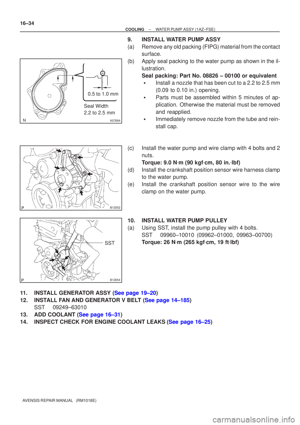
9.INSTALL WATER PUMP ASSY
(a)Remove any old packing (FIPG) material from the contact surface.
(b)Apply seal packing to the water pump as shown in the il- lustration.
Seal packing: Part No. 08826 ± 00100 or equivalent
�Install a nozzle that has been cut to a 2.2 to 2.5 mm
(0.09 to 0.10 in.) opening.
�Parts must be assembled within 5 minutes of ap-
plication. Otherwise the material must be removed
and reapplied.
�Immediately remove nozzle from the tube and rein-
stall cap.
(c)Install the water pump and wire clamp with 4 bolts and 2 nuts.
Torque: 9.0 N �m (90 kgf �cm, 80 in. �lbf)
(d)Install the crankshaft position sensor wire harness clamp to the water pump.
(e)Install the crankshaft position sensor wire to the wire clamp on the water pump.
10.INSTALL WATER PUMP PULLEY
(a)Using SST, install the pump pulley with 4 bolts. SST09960±10010 (09962±01000, 09963±00700)
Torque: 26 N �m (265 kgf �cm, 19 ft �lbf)
11.INSTALL GENERATOR ASSY (See page 19±20)
12.INSTALL FAN AND GENERATOR V BELT (See page 14±185) SST 09249±63010
13.ADD COOLANT (See page 16±31)
14.INSPECT CHECK FOR ENGINE COOLANT LEAKS(See page 16±25)