Page 2177 of 5135
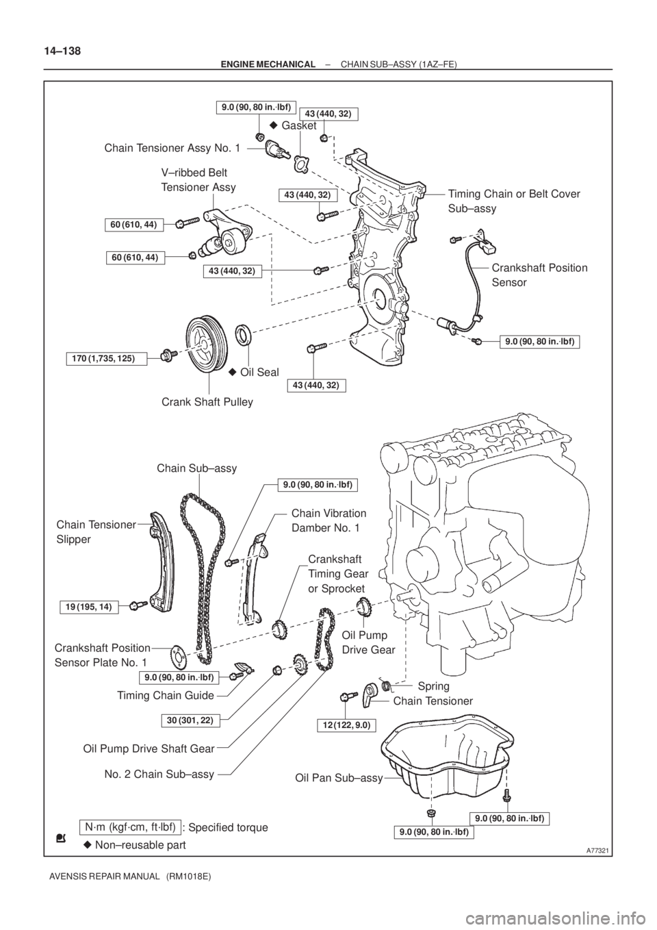
A77321
N´m (kgf´cm, ft´lbf)
: Specified torque
� Non±reusable part
43 (440, 32)
� Gasket
Chain Tensioner Assy No. 1
Timing Chain or Belt Cover
Sub±assy
Crankshaft Position
Sensor
9.0 (90, 80 in.�lbf)
V±ribbed Belt
Tensioner Assy
60 (610, 44)
60 (610, 44)
43 (440, 32)
43 (440, 32)
170 (1,735, 125)
Crank Shaft Pulley
� Oil Seal
43 (440, 32)
Chain Sub±assy
Chain Tensioner
Slipper
Chain Vibration
Damber No. 1
Crankshaft
Timing Gear
or Sprocket
19 (195, 14)
Crankshaft Position
Sensor Plate No. 1
Timing Chain Guide
Oil Pump
Drive Gear
12 (122, 9.0)
Spring
Chain Tensioner
Oil Pump Drive Shaft Gear
Oil Pan Sub±assy
9.0 (90, 80 in.�lbf)
9.0 (90, 80 in.�lbf)
9.0 (90, 80 in.�lbf)
30 (301, 22)
No. 2 Chain Sub±assy
9.0 (90, 80 in.�lbf)
9.0 (90, 80 in.�lbf)
14±138
± ENGINE MECHANICALCHAIN SUB±ASSY (1AZ±FE)
AVENSIS REPAIR MANUAL (RM1018E)
Page 2185 of 5135
A77286
Push
A64641
A00019
A77288
14±226
±
ENGINE MECHANICAL CHAIN SUB±ASSY(1AZ±FSE)
AVENSIS REPAIR MANUAL (RM1018E)
30.REMOVE CHAIN TENSIONER ASSY NO.1
(a)Remove the 2 nuts, the chain tensioner No. 1 and gasket.
NOTICE:
Do not turn the crankshaft.
31.REMOVE CRANKSHAFT POSITION SENSOR (See page 18±17) 32. REMOVE OIL PAN SUB±ASSY
(a) Remove the 12 bolts and 2 nuts.
(b) Insert the blade of SST between the crank case, timingchain cover and oil pan, cut off applied sealer and remove
the oil pan.
SST 09032±00100
NOTICE:
Be careful not to damage the contact surface of the timing
chain cover, crank case and oil pan.
33. REMOVE V±RIBBED BELT TENSIONER ASSY
(a) Remove the bolt and nut, and then remove the V±ribbed belt tensioner.
Page 2186 of 5135
A77289
Pry
A77243
± ENGINE MECHANICALCHAIN SUB±ASSY (1AZ±FSE)
14±227
AVENSIS REPAIR MANUAL (RM1018E)
34. REMOVE TIMING CHAIN OR BELT COVER
SUB±ASSY
(a) Remove the 14 bolts and 2 nuts.
(b) Using a screwdriver, pry between the timing chain cover
and cylinder head or cylinder block.
(c) Remove the timing chain cover.
NOTICE:
Be careful not to damage the contact surface of the timing
chain cover, cylinder head and cylinder block.
35. REMOVE CRANKSHAFT POSITION SENSOR PLATE NO.1
36. REMOVE CHAIN TENSIONER SLIPPER
(a) Remove the 2 bolts and the chain tensioner slipper.
37. REMOVE CHAIN VIBRATION DAMPER NO.1
(a) Remove the bolt and the chain vibration damper No. 1
38. REMOVE TIMING CHAIN GUIDE
(a) Remove the bolt and the timing chain guide.
39. REMOVE CHAIN SUB±ASSY
40. REMOVE CRANKSHAFT TIMING GEAR OR SPROCKET
Page 2190 of 5135

14±231
AVENSIS REPAIR MANUAL (RM1018E)
47. INSTALL TIMING CHAIN GUIDE
Torque: 9.0 N�m (92 kgf�cm, 80 in.")
A77290
Hold
Stopper
A32629
A77390Seal Packing
± ENGINE MECHANICALCHAIN SUB±ASSY (1AZ±FSE)
14±231
AVENSIS REPAIR MANUAL (RM1018E)
47. INSTALL TIMING CHAIN GUIDE
Torque: 9.0 N�m (92 kgf�cm, 80 in.�lbf)
48. INSTALL CHAIN TENSIONER SLIPPER
(a) Install the chain tensioner slipper with bolt.
Torque: 19 N�m (195 kgf�cm, 14 ft�lbf)
(b) Check that the chain tensioner slipper is held on the cylin-
der block stopper.
49. INSTALL CRANKSHAFT POSITION SENSOR PLATE
NO.1
(a) Install the plate with the ºFº mark facing forward.
50. INSTALL TIMING CHAIN OR BELT COVER SUB±ASSY
NOTICE:
�Remove any oil from the contact surface.
�Install the chain cover within 3 minutes after applying
seal packing.
�Do not start the engine within 2 hours after installing.
(a) Remove any old packing (FIPG) material and be careful
not to drop any oil on the contact surfaces of the timing
chain cover.
(b) Apply a continuous bead (Diameter 2 mm (0.09 in.)) of
seal packing as shown in the illustration.
Seal packing: Part No. 08826 ± 00080 or equivalent.
Page 2192 of 5135

14±233
AVENSIS REPAIR MANUAL (RM1018E)
52.INSTALL OIL PAN SUB±ASSY
NOTICE:
�Remov")
A77392
Seal Packing6mm
A64641
A77393
SST
A77394
Raise
Pin Hook
Push
±
ENGINE MECHANICAL CHAIN SUB±ASSY(1AZ±FSE)
14±233
AVENSIS REPAIR MANUAL (RM1018E)
52.INSTALL OIL PAN SUB±ASSY
NOTICE:
�Remove any oil from the contact surface.
�Install the oil pan within 3 minutes after applying seal
packing.
�Do not start the engine within 2 hours after installing.
(a)Remove any old packing (FIPG) material and be careful
not to drop any oil on the contact surface of the cylinder
block and oil pan.
(b)Apply a continuous bead (Diameter 3 mm to 4 mm (0.157 in.)) of seal packing as shown in the illustration, and install
the oil pan.
Seal packing: part No. 08826 ± 00080 or equivalent
(c)Install the oil pan with the 12 bolts and 2 nuts. Torque: 9.0 N �m (92 kgf �cm,80 in. �lbf)
53.INSTALL CRANKSHAFT POSITION SENSOR (See page 18±17) 54. INSTALL CRANKSHAFT PULLEY
(a) Using SST, tighten the set bolt.SST 09213±54015 (91651±60855), 09330±00021
Torque: 170 N �m (1,733 kgf �cm, 125 ft �lbf)
55. INSTALL CHAIN TENSIONER ASSY NO.1
(a) Release the ratchet pawl, fully push in the plunger and ap- ply the hook to the pin so that the plunger is located in
position.
Page 2199 of 5135
A77321
N´m (kgf´cm, ft´lbf)
: Specified torque
� Non±reusable part
43 (440, 32)
� Gasket
Chain Tensioner Assy No. 1
Timing Chain or Belt Cover
Sub±assy
Crankshaft Position
Sensor
9.0 (90, 80 in.�lbf)
V±ribbed Belt
Tensioner Assy
60 (610, 44)
60 (610, 44)
43 (440, 32)
43 (440, 32)
170 (1,735, 125)
Crank Shaft Pulley
� Oil Seal
43 (440, 32)
Chain Sub±assy
Chain Tensioner
Slipper
Chain Vibration
Damber No. 1
Crankshaft
Timing Gear
or Sprocket
19 (195, 14)
Crankshaft Position
Sensor Plate No. 1
Timing Chain Guide
Oil Pump
Drive Gear
12 (122, 9.0)
Spring
Chain Tensioner
Oil Pump Drive Shaft Gear
Oil Pan Sub±assy
9.0 (90, 80 in.�lbf)
9.0 (90, 80 in.�lbf)
9.0 (90, 80 in.�lbf)
30 (301, 22)
No. 2 Chain Sub±assy
9.0 (90, 80 in.�lbf)
9.0 (90, 80 in.�lbf)
± ENGINE MECHANICALCHAIN SUB±ASSY (1AZ±FSE)
14±221
AVENSIS REPAIR MANUAL (RM1018E)
Page 2208 of 5135

AVENSIS REPAIR MANUAL (RM1018E)
94.REMOVE WATER BY±PASS PIPE NO.1
(a)Remove the 2 bolts and 2 nuts.
(b)Remove t")
A78645
Oil Pressure Switch
14±212
±
ENGINE MECHANICAL PARTIAL ENGINE ASSY(1AZ±FSE)
AVENSIS REPAIR MANUAL (RM1018E)
94.REMOVE WATER BY±PASS PIPE NO.1
(a)Remove the 2 bolts and 2 nuts.
(b)Remove the water by±pass pipe No. 1 and a gasket.
95.REMOVE KNOCK SENSOR
(a)Remove the nut and the knock sensor. 96.REMOVE ENGINE OIL PRESSURE SWITCH ASSY
(a)Using SST, remove the engine oil pressure switch.SST09268±46021
97.REMOVE E.F.I. ENGINE COOLANT TEMPERATURE SENSOR
(a)Using a SST, remove the coolant temperature sensor SST09817±33190
98.REPLACE PARTIAL ENGINE ASSY
99.INSTALL E.F.I. ENGINE COOLANT TEMPERATURE SENSOR
(a)Install a new gasket to the engine coolant temperature sensor.
(b)Using SST, install the engine coolant temperature sensor. SST09817±33190
Torque: 20 N �m (208 kgf �cm,15 ft �lbf)
100.INSTALL ENGINE OIL PRESSURE SWITCH ASSY
(a)Clean the threads of the oil pressure switch, apply adhesive there.
Adhesive: Part No. 08833 ± 00080 THREE BOND 1344 or equivalent.
(b)Install the oil pressure switch. Torque: 15 N �m (153 kgf �cm,11 ft �lbf)
SST09268±46021
101.INSTALL KNOCK SENSOR Torque: 20 N �m (208 kgf �cm,15 ft �lbf)
102.INSTALL WATER BY±PASS PIPE NO.1
(a)Install the water by±pass pipe No. 1 and a new gasket.
(b)Install the 2 bolts and 2 nuts. Torque: 9.0 N �m (92 kgf �cm,80 in. �lbf)
103.INSTALL THERMOSTAT (See page 16±35)
104. INSTALL WATER INLET Torque: 9.0 N �m (92 kgf �cm, 80 in. �lbf)
105. INSTALL OIL LEVEL GAGE GUIDE
(a) Apply a light coat of engine oil to the O±ring, install it to the oil\
level gauge guide.
(b) Install the oil level gauge and guide with the bolt. Torque: 9.0 N �m (92 kgf �cm, 80 in. �lbf)
Page 2213 of 5135

14±217
AVENSIS REPAIR MANUAL (RM1018E)
158.INSTALL OIL RESERVOIR BRACKET NO.1
Torque: 8.0 N �m (82 kgf �cm,71 in. �lbf)
159.INSTALL RETURN TUBE SU")
±
ENGINE MECHANICAL PARTIAL ENGINE ASSY(1AZ±FSE)
14±217
AVENSIS REPAIR MANUAL (RM1018E)
158.INSTALL OIL RESERVOIR BRACKET NO.1
Torque: 8.0 N �m (82 kgf �cm,71 in. �lbf)
159.INSTALL RETURN TUBE SUB±ASSY
Torque: 8.0 N �m (82 kgf �cm,71 in. �lbf)
160.INSTALL RADIATOR RESERVE TANK SUB±ASSY Torque: 5.0 N �m (51 kgf �cm,44 in. �lbf)
161.INSTALL BATTERY CARRIER
162.INSTALL AIR CLEANER ASSEMBLY WITH HOSE
Torque: 5.0 N �m (51 kgf �cm,44 in. �lbf)
163.INSTALL COMPRESSOR AND MAGNETIC CLUTCH Torque: 25 N �m (255 kgf �cm,18 in. �lbf)
164.INSTALL GENERATOR ASSY (See page 19±20)
165.INSTALL FAN AND GENERATOR V BELT (See page 14±185)
166.INSTALL RADIATOR ASSY (See page 16±36)
167. INSTALL RADIATOR RELAY BLOCK Torque: 5.0 N �m (51 kgf �cm, 44 in. �lbf)
168. INSTALL ENGINE COVER SUB±ASSY NO.1 Torque: 7.0 N �m (71 kgf �cm, 62 in. �lbf)
169. ADD MANUAL TRANSAXLE OIL (M/T TRANSAXLE)
170. ADD AUTOMATIC TRANSAXLE FLUID (A/T TRANSAXLE)
171. ADD ENGINE OIL
172.ADD COOLANT (See page 16±31)
173.ADD POWER STEERING FLUID (See page 51±4)
174. BLEED POWER STEERING FLUID
175. CHECK FOR ENGINE OIL LEAKS
176.CHECK FOR ENGINE COOLANT LEAKS (See page 16±25)
177.CHECK FOR FUEL LEAKS (See page 11±30)
178. INSTALL FRONT WHEELS Torque: 103 N �m (1,050 kgf �cm, 76 ft �lbf)
179.ADJUST FRONT WHEEL ALIGNMENT (See page 26±6)
180.INSPECT CHECK IDLE SPEED AND IGNITION TIMING (See page 14±204)
181. INSPECT CO/HC
182. CHECK ABS SPEED SENSOR SIGNAL

AVENSIS REPAIR MANUAL (RM1018E)
30.REMOVE CHAIN TENSIONER ASSY NO.1
(a)Remove the 2 nuts, the chain tensioner")

14±227
AVENSIS REPAIR MANUAL (RM1018E)
34. REMOVE TIMING CHAIN OR BELT COVER
SUB±ASSY
(a) Remove the 14 bolts and 2 nuts.
(b) Using")
