Page 2102 of 5135
14±104
± ENGINE MECHANICALENGINE (1AZ±FE)
AVENSIS REPAIR MANUAL (RM1018E)CO
HCProblemsCauses
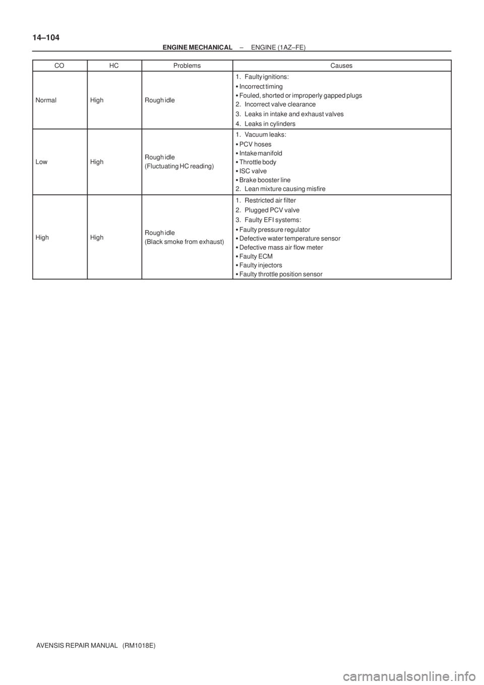
NormalHighRough idle
1. Faulty ignitions:
�Incorrect timing
�Fouled, shorted or improperly gapped plugs
2. Incorrect valve clearance
3. Leaks in intake and exhaust valves
4. Leaks in cylinders
LowHighRough idle
(Fluctuating HC reading)
1. Vacuum leaks:
�PCV hoses
�Intake manifold
�Throttle body
�ISC valve
�Brake booster line
2. Lean mixture causing misfire
HighHighRough idle
(Black smoke from exhaust)
1. Restricted air filter
2. Plugged PCV valve
3. Faulty EFI systems:
�Faulty pressure regulator
�Defective water temperature sensor
�Defective mass air flow meter
�Faulty ECM
�Faulty injectors
�Faulty throttle position sensor
Page 2110 of 5135

14±83
AVENSIS REPAIR MANUAL (RM1018E)
22. DISCONNECT VENTILATION HOSE
(a) Disconnect the ventilation hose fro")
A65078
A64058
A79363
A64026
± ENGINE MECHANICALCYLINDER HEAD GASKET (1ZZ±FE/3ZZ±FE)
14±83
AVENSIS REPAIR MANUAL (RM1018E)
22. DISCONNECT VENTILATION HOSE
(a) Disconnect the ventilation hose from the cylinder head
cover.
23. DISCONNECT VENTILATION HOSE NO.2
(a) Disconnect the ventilation hose from the cylinder head
cover.
24. REMOVE INTAKE MANIFOLD
(a) Disconnect the 2 water hoses from the throttle body.
(b) Disconnect the ventilation hose and ventilation hose No.
2 from the cylinder head cover.
(c) Disconnect the vacuum hose from the water by±pass
pipe No. 1.
(d) Remove the 4 bolts, 2 nuts and 2 wire brackets.
(e) Remove the intake manifold and the throttle body assem-
bly.
(f) Remove the gasket from the intake manifold and the
throttle body assembly.
25. REMOVE OIL LEVEL GAGE SUB±ASSY
(a) Remove the oil level gage from the oil level gage guide.
26. REMOVE OIL LEVEL GAGE GUIDE
(a) Disconnect the crankshaft position sensor cramp.
(b) Remove the bolt and the oil level gage guide.
27. SEPARATE WATER BY±PASS PIPE NO.1
(a) Remove the 2 bolts which are used to secure the water
by±pass pipe.
Page 2113 of 5135

AVENSIS REPAIR MANUAL (RM1018E)
38. REMOVE TRANSVERSE ENGINE ENGINE
MOUNTING BRACKET
(a) Rem")
A12816
A76692
A62178
Push
A10076
A30848
14±86
± ENGINE MECHANICALCYLINDER HEAD GASKET (1ZZ±FE/3ZZ±FE)
AVENSIS REPAIR MANUAL (RM1018E)
38. REMOVE TRANSVERSE ENGINE ENGINE
MOUNTING BRACKET
(a) Remove the 3 bolts and the transverse engine engine
mounting bracket.
39. REMOVE CRANKSHAFT POSITION SENSOR
(a) Remove the 2 bolts which are used to secure the crank-
shaft position sensor.
40. REMOVE CHAIN TENSIONER ASSY NO.1
(a) Remove the 2 nuts and the chain tensioner.
NOTICE:
Do not revolve the crankshaft without the chain tensioner.
41. REMOVE TIMING CHAIN OR BELT COVER
SUB±ASSY
(a) Remove the 11 bolts and nuts.
(b) Using a torx wrench socket (E8), remove the stud bolt.
(c) Remove the timing chain cover by prying between the cyl-
inder head and the cylinder block with a screwdriver.
NOTICE:
Be careful not to damage the timing chain cover, the cylin-
der head and the cylinder block.
42. REMOVE TIMING GEAR COVER OIL SEAL
(a) Using a screwdriver, remove the oil seal.
43. REMOVE CRANKSHAFT POSITION SENSOR PLATE
NO.1
44. REMOVE CHAIN TENSIONER SLIPPER
(a) Remove the bolt and the chain tensioner slipper.
45. REMOVE CHAIN VIBRATION DAMPER NO.1
(a) Remove the 2 bolt and the chain vibration damper.
Page 2116 of 5135

14±89
AVENSIS REPAIR MANUA")
A62170
Set KeyUpward
A62171
Yellow
Color Link
Timing Mark
A62172
SST
A62173
Yellow Color Mark
Timing Mark
A30867
± ENGINE MECHANICALCYLINDER HEAD GASKET (1ZZ±FE/3ZZ±FE)
14±89
AVENSIS REPAIR MANUAL (RM1018E)
(2) Using a crankshaft pulley bolt, turn the crankshaft
and set the set key on the crankshaft upward.
(b) Install the timing chain on the crankshaft timing sprocket
with the yellow color link and the timing mark on the crank-
shaft timing sprocket aligned.
HINT:
Three yellow color links are on the chain.
(c) Using SST, install the crankshaft timing sprocket.
SST 09223±22010
(d) Install the timing chain to the camshaft timing sprockets
with the yellow color links and the timing marks on the
camshaft timing sprockets aligned.
55. INSTALL CHAIN VIBRATION DAMPER NO.1
(a) Install chain vibration damper with the 2 bolts.
Torque: 9.0 N�m (92 kgf�cm, 80 in.�lbf)
56. INSTALL CHAIN TENSIONER SLIPPER
(a) Install the chain tensioner slipper with the bolt.
Torque: 19 N�m (194 kgf�cm, 14 ft�lbf)
57. INSTALL CRANKSHAFT POSITION SENSOR PLATE
NO.1
(a) Install the plate with the ºFº mark facing forward.
Page 2118 of 5135

14±91
AVENSIS REPAIR MANUAL (RM1018E)
(c) Install the timing cha")
A65677
A
A
AA
A
A
AAA B
B
B
A62177
Raise
Push
Hook
Pin
A62178
Push
A76692
± ENGINE MECHANICALCYLINDER HEAD GASKET (1ZZ±FE/3ZZ±FE)
14±91
AVENSIS REPAIR MANUAL (RM1018E)
(c) Install the timing chain cover with the 11 bolts and nut.
Torque:
13 N�m (133 kgf�cm, 10 ft�lbf) for A
19 N�m (194 kgf�cm, 14 ft�lbf) for B
(d) Using a torx wrench socket (E8), install the stud bolt.
Torque: 9.5 N�m (97 kgf�cm, 84 in.�lbf)
60. INSTALL CHAIN TENSIONER ASSY NO.1
(a) Check that the O±ring is clean, and set the hook as shown
in the illustration.
(b) Apply engine oil to the chain tensioner and install it with
the 2 nuts.
Torque: 9.0 N�m (92 kgf�cm, 80 in.�lbf)
NOTICE:
If the hook released the plunger during installation, re±
hook the plunger by the hook to fix it.
61. INSTALL CRANKSHAFT POSITION SENSOR
(a) Apply a light coat of the engine oil to the O±ring on the
crankshaft position sensor.
(b) Install the crankshaft position sensor with the 2 bolts.
Torque: 9.0 N�m (92 kgf�cm, 80 in.�lbf)
Page 2126 of 5135
A60625
Crankshaft Pulley V±ribbed Belt
Tensioner Assy
Water Pump AssyTransverse Engine
Engine Mounting Bracket
Crankshaft Position Sensor Chain Tensioner Assy No. 1
Timing Chain or
Belt Cover Sub±assy
� Oil Seal
Crankshaft Position Sensor
Plate No. 1Chain Sub±assy
Chain Tensioner Slipper
Crankshaft timing Sprocket� O±ring
� Non±reusable part
N´m (kgf´cm, ft´lbf) : Specified torque
47 (479, 35)
29 (296, 21)
69 (704, 51)
138 (1,047, 102)
13 (133, 10)
9.0 (92, 80 in.�lbf)
9.0 (92, 80 in.�lbf)
19 (194, 14)
9.0 (92, 80 in.�lbf) (L=20)
11 (112, 8) (L=35)
9.5 (97, 84 in.�lbf)
13 (133, 10) (M6)
19 (194, 14) (M8)
± ENGINE MECHANICALCYLINDER HEAD GASKET (1ZZ±FE/3ZZ±FE)
14±79
AVENSIS REPAIR MANUAL (RM1018E)
Page 2130 of 5135

14±183
AVENSIS REPAIR MANUAL (RM1018E)
(e)Inspect cylinder compression pressure.
SST09992±00500
(1)Insert a compression gauge into the spark plughole.")
A79033
±
ENGINE MECHANICAL ENGINE(1AZ±FSE)
14±183
AVENSIS REPAIR MANUAL (RM1018E)
(e)Inspect cylinder compression pressure.
SST09992±00500
(1)Insert a compression gauge into the spark plughole.
(2)Fully open the throttle.
(3)While cranking the engine, measure the compres- sion pressure.
Compression pressure:
1,300 kPa (13.3 kgf/cm
2, 189 psi)
Minimum pressure:
1000 kPa (10.2 kgf/cm
2, 145 psi)
Difference between each cylinder:
100 kPa (1.0 kgf/cm
2, 14 psi)
NOTICE:
�Always use a fully charged battery to obtain engine
speed of 250 rpm or more.
�Check other cylinder's compression pressure in the
same way.
�This measurement must be done in as short a time as
possible.
(4)If the cylinder compression is low, pour a small amount of engine oil into the cylinder through the
spark plug hole and inspect again.
HINT:
�If adding oil increases the compression, the piston rings
and/or cylinder bore may be worn or damaged.
�If pressure stays low, a valve may be sticking or seating
improperly, or there may be leakage past the gasket.
10.INSPECT CO/HC
(a)Start the engine.
(b)Run the engine at 2,500 rpm for approximately 180 seconds.
(c)Insert CO/HC meter testing probe at least 40 cm (1.3 ft) into the tail\
pipe during idling.
(d)Check CO/HC concentration at idle. Idle CO concentration: 0 to 0.5 %
Idle HC concentration: Applicable local regulation
(e)If the CO/HC concentration does not conform to specifications, perform troubleshooting in the order given below.
(1)Check heated oxygen sensor operation. (See page 12±6)
(2) See the table below for possible causes, and then inspect and repair the applicable causes ifnecessary.
Page 2131 of 5135
14±184
± ENGINE MECHANICALENGINE (1AZ±FSE)
AVENSIS REPAIR MANUAL (RM1018E)CO
HCProblemsCauses
NormalHighRough idle
1. Faulty ignitions:
�Incorrect timing
�Fouled, shorted or improperly gapped plugs
2. Incorrect valve clearance
3. Leaks in intake and exhaust valves
4. Leaks in cylinders
LowHighRough idle
(Fluctuating HC reading)
1. Vacuum leaks:
�PCV hoses
�Intake manifold
�Throttle body
�ISC valve
�Brake booster line
2. Lean mixture causing misfire
HighHighRough idle
(Black smoke from exhaust)
1. Restricted air filter
2. Plugged PCV valve
3. Faulty EFI systems:
�Faulty pressure regulator
�Defective water temperature sensor
�Defective mass air flow meter
�Faulty ECM
�Faulty injectors
�Faulty throttle position sensor