Page 2031 of 5135

A12816
A76692
A62178
Push
A10076
A30848
14±52
± ENGINE MECHANICALCHAIN SUB±ASSY (1ZZ±FE/3ZZ±FE)
AVENSIS REPAIR MANUAL (RM1018E)
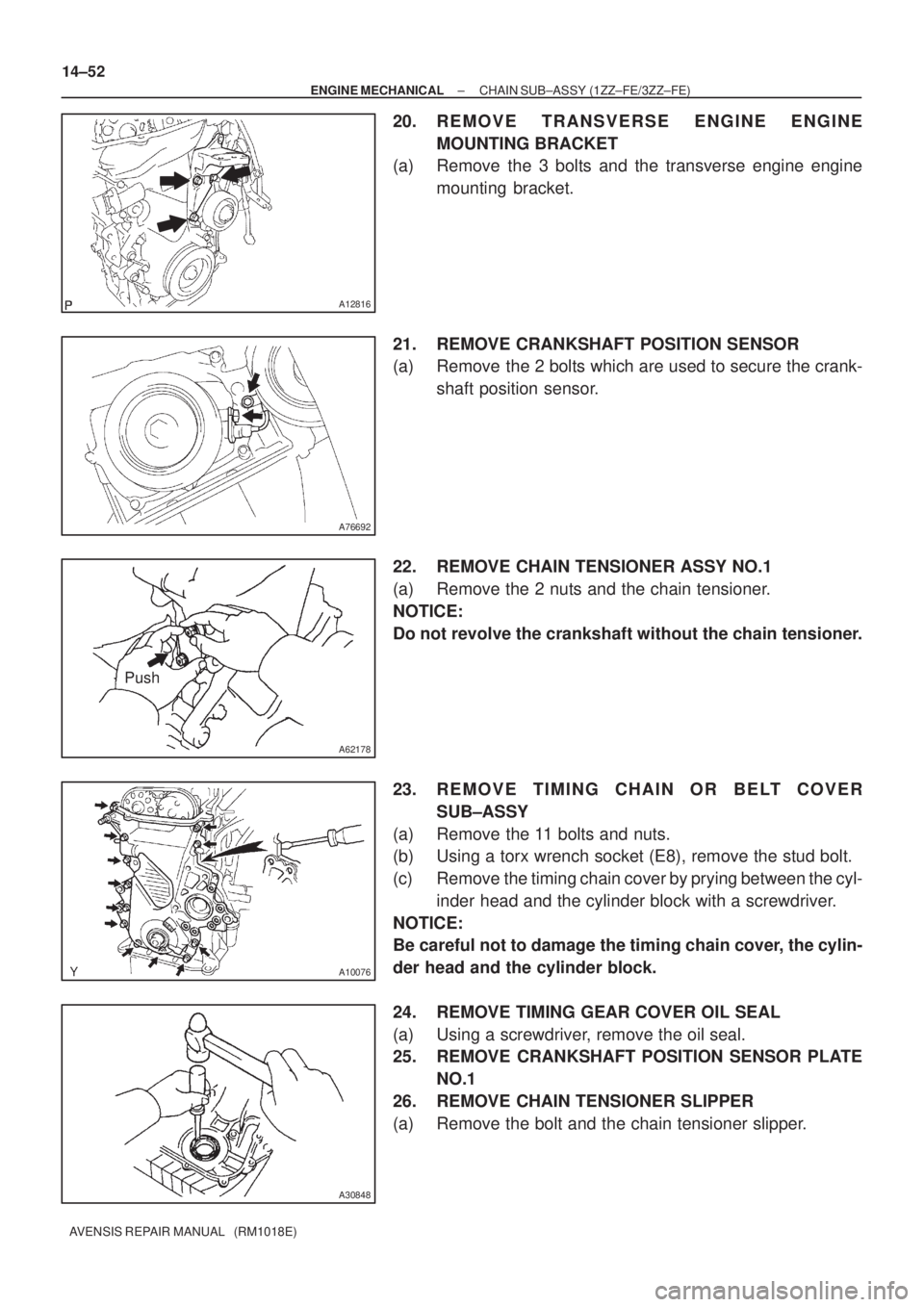
20. REMOVE TRANSVERSE ENGINE ENGINE
MOUNTING BRACKET
(a) Remove the 3 bolts and the transverse engine engine
mounting bracket.
21. REMOVE CRANKSHAFT POSITION SENSOR
(a) Remove the 2 bolts which are used to secure the crank-
shaft position sensor.
22. REMOVE CHAIN TENSIONER ASSY NO.1
(a) Remove the 2 nuts and the chain tensioner.
NOTICE:
Do not revolve the crankshaft without the chain tensioner.
23. REMOVE TIMING CHAIN OR BELT COVER
SUB±ASSY
(a) Remove the 11 bolts and nuts.
(b) Using a torx wrench socket (E8), remove the stud bolt.
(c) Remove the timing chain cover by prying between the cyl-
inder head and the cylinder block with a screwdriver.
NOTICE:
Be careful not to damage the timing chain cover, the cylin-
der head and the cylinder block.
24. REMOVE TIMING GEAR COVER OIL SEAL
(a) Using a screwdriver, remove the oil seal.
25. REMOVE CRANKSHAFT POSITION SENSOR PLATE
NO.1
26. REMOVE CHAIN TENSIONER SLIPPER
(a) Remove the bolt and the chain tensioner slipper.
Page 2033 of 5135
A62173
Yellow Color Link
Timing Mark
A30867
A62174
SST
A62175
Seal Width
4 to 5 mm
Seal Packing
14±54
± ENGINE MECHANICALCHAIN SUB±ASSY (1ZZ±FE/3ZZ±FE)
AVENSIS REPAIR MANUAL (RM1018E)
(d) Install the timing chain to the camshaft timing sprockets
with the yellow color links aligned with the timing marks on
the camshaft timing sprockets.
29. INSTALL CHAIN TENSIONER SLIPPER
(a) Install the chain tensioner slipper with the bolt.
Torque: 19 N�m (194 kgf�cm, 14 ft�lbf)
30. INSTALL CRANKSHAFT POSITION SENSOR PLATE
NO.1
(a) Install the plate with the ºFº mark facing outward.
31. INSTALL TIMING GEAR COVER OIL SEAL
(a) Apply MP grease to a new oil seal lip.
(b) Using SST, tap in the oil seal until its surface is flush with
the timing chain cover edge.
SST 09223±22010
NOTICE:
Keep the lip free of foreign objects.
32. INSTALL TIMING CHAIN OR BELT COVER SUB±ASSY
(a) Remove any old packing (FIPG) material from the contact
surface.
Page 2035 of 5135

A62177
Raise
Push
Hook
Pin
A62178
Push
A76692
A12816
A11858
14±56
±
ENGINE MECHANICAL CHAIN SUB±ASSY(1ZZ±FE/3ZZ±FE)
AVENSIS REPAIR MANUAL (RM1018E)
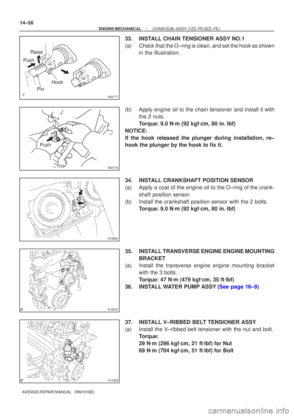
33.INSTALL CHAIN TENSIONER ASSY NO.1
(a)Check that the O±ring is clean, and set the hook as shown in the illustration.
(b)Apply engine oil to the chain tensioner and install it with the 2 nuts.
Torque: 9.0 N �m (92 kgf �cm, 80 in. �lbf)
NOTICE:
If the hook released the plunger during installation, re±
hook the plunger by the hook to fix it.
34.INSTALL CRANKSHAFT POSITION SENSOR
(a)Apply a coat of the engine oil to the O±ring of the crank- shaft position sensor.
(b)Install the crankshaft position sensor with the 2 bolts. Torque: 9.0 N �m (92 kgf �cm, 80 in. �lbf)
35.INSTALL TRANSVERSE ENGINE ENGINE MOUNTING BRACKET
(a)Install the transverse engine engine mounting bracket with the 3 bolts.
Torque: 47 N �m (479 kgf �cm, 35 ft �lbf)
36.INSTALL WATER PUMP ASSY(See page 16±9)
37. INSTALL V±RIBBED BELT TENSIONER ASSY
(a) Install the V±ribbed belt tensioner with the nut and bolt. Torque:
29 N�m (296 kgf �cm, 21 ft �lbf) for Nut
69 N �m (704 kgf �cm, 51 ft �lbf) for Bolt
Page 2042 of 5135
A60625
Crankshaft Pulley V±ribbed Belt
Tensioner Assy
Water Pump AssyTransverse Engine
Engine Mounting Bracket
Crankshaft Position Sensor Chain Tensioner Assy No. 1
Timing Chain or
Belt Cover Sub±assy
� Oil Seal
Crankshaft Position Sensor
Plate No. 1Chain Sub±assy
Chain Tensioner Slipper
Crankshaft timing Sprocket� O±ring
� Non±reusable part
N´m (kgf´cm, ft´lbf) : Specified torque
47 (479, 35)
29 (296, 21)
69 (704, 51)
138 (1,047, 102)
13 (133, 10)
9.0 (92, 80 in.�lbf)
9.0 (92, 80 in.�lbf)
19 (194, 14)
9.0 (92, 80 in.�lbf) (L=20)
11 (112, 8) (L=35)
9.5 (97, 84 in.�lbf)
13 (133, 10) (M6)
19 (194, 14) (M8)
14±48
± ENGINE MECHANICALCHAIN SUB±ASSY (1ZZ±FE/3ZZ±FE)
AVENSIS REPAIR MANUAL (RM1018E)
Page 2050 of 5135
A76713
A64023
A79363
A64026
14±34
±
ENGINE MECHANICAL PARTIAL ENGINE ASSY (1ZZ±FE/3ZZ±FE)
AVENSIS REPAIR MANUAL (RM1018E)
(b) Remove the 2 nuts which are used to secure the engine wire.
(c) Remove the 4 bolts and the 4 ignition coils.
69. REMOVE FUEL DELIVERY PIPE SUB±ASSY (See page 11±11)
70. REMOVE INTAKE MANIFOLD
(a) Disconnect the 2 water hoses from the throttle body.
(b) Disconnect the ventilation hose and the ventilation hose No. 2 from the cylinder head cover.
(c) Disconnect the vacuum hose from the water by±pass
pipe No. 1.
(d) Remove the 4 bolts, 2 nuts and 2 wire brackets,then re- move the intake manifold and the throttle body assembly.
(e) Remove the gasket from the intake manifold and the
throttle body assembly.
71. REMOVE OIL LEVEL GAGE SUB±ASSY
(a) Remove the oil level gage from the oil level gage guide.
72. REMOVE OIL LEVEL GAGE GUIDE
(a) Disconnect the crank shaft position sensor cramp.
(b) Remove the bolt and the oil level gage guide.
Page 2051 of 5135
A64027
A64028
B00084
A76692
A64029
±
ENGINE MECHANICAL PARTIAL ENGINE ASSY (1ZZ±FE/3ZZ±FE)
14±35
AVENSIS REPAIR MANUAL (RM1018E)
73. REMOVE WATER BY±PASS PIPE NO.1
(a) Disconnect the knock sensor cramp.
(b) Remove the 2 bolts and 2 nuts, then detach the water by±
pass pipe and the gasket.
74. REMOVE WATER INLET
(a) Remove the 2 nuts and the water inlet.
75. REMOVE THERMOSTAT
76. REMOVE ENGINE OIL PRESSURE SWITCH ASSY (See page 17±1)
77. REMOVE CAMSHAFT POSITION SENSOR
(a) Remove the bolt and the camshaft position sensor.
78. REMOVE CRANKSHAFT POSITION SENSOR
(a) Remove the 2 bolts and the crankshaft position sensor.
79. REMOVE KNOCK SENSOR
(a) Remove the nut and the knock sensor.
Page 2053 of 5135
A76722
A76723
A64033
A64034
A64034
± ENGINE MECHANICALPARTIAL ENGINE ASSY (1ZZ±FE/3ZZ±FE)
14±37
AVENSIS REPAIR MANUAL (RM1018E)
85. REMOVE EXHAUST MANIFOLD HEAT INSULATOR
NO.1
(a) Disconnect the heated oxygen sensor connector.
(b) Remove the 3 bolts and the nut, and then remove the ex-
haust manifold heat insulator.
86. REMOVE EXHAUST MANIFOLD
(a) Remove the 5 nuts, then remove the exhaust manifold
and the gasket.
87. REMOVE ENGINE COOLANT TEMPERATURE
SENSOR
(a) Using SST, remove the engine coolant temperature sen-
sor.
SST 09817±33190
88. REMOVE RADIO SETTING CONDENSER
(a) Remove the bolt and the condenser.
89. REMOVE WATER BY±PASS HOSE NO.2
90. REMOVE RADIATOR HOSE INLET
91. REMOVE HEATER INLET WATER HOSE
92. REPLACE PARTIAL ENGINE ASSY
93. INSTALL RADIO SETTING CONDENSER
(a) Install the condenser with the bolt.
Torque: 10 N�m (102 kgf�cm, 7 ft�lbf)
Page 2054 of 5135

A64033
A76723
A76722
A76721
A76720
ABB 14±38
± ENGINE MECHANICALPARTIAL ENGINE ASSY (1ZZ±FE/3ZZ±FE)
AVENSIS REPAIR MANUAL (RM1018E)
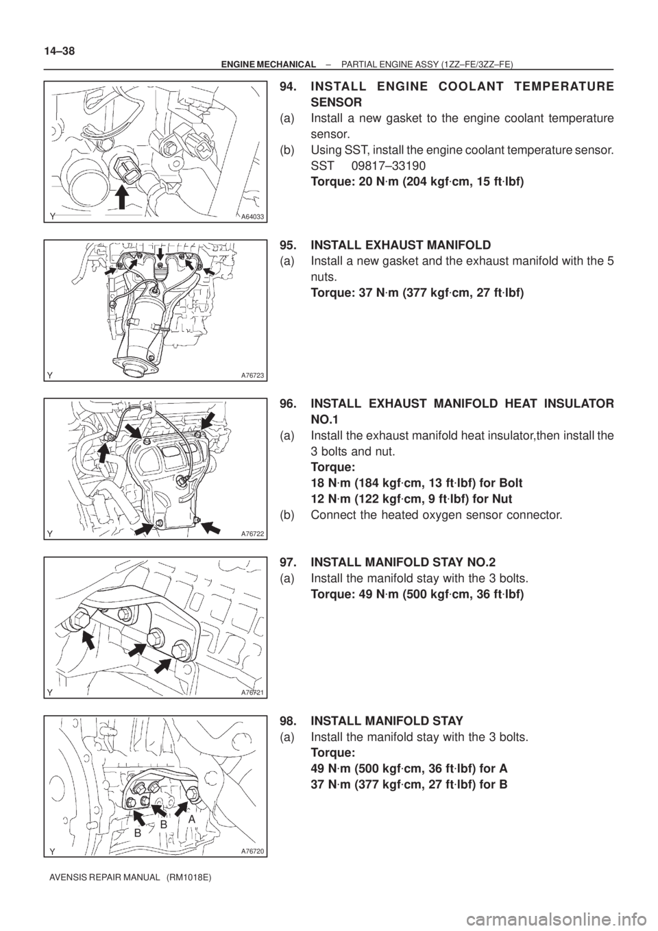
94. INSTALL ENGINE COOLANT TEMPERATURE
SENSOR
(a) Install a new gasket to the engine coolant temperature
sensor.
(b) Using SST, install the engine coolant temperature sensor.
SST 09817±33190
Torque: 20 N�m (204 kgf�cm, 15 ft�lbf)
95. INSTALL EXHAUST MANIFOLD
(a) Install a new gasket and the exhaust manifold with the 5
nuts.
Torque: 37 N�m (377 kgf�cm, 27 ft�lbf)
96. INSTALL EXHAUST MANIFOLD HEAT INSULATOR
NO.1
(a) Install the exhaust manifold heat insulator,then install the
3 bolts and nut.
Torque:
18 N�m (184 kgf�cm, 13 ft�lbf) for Bolt
12 N�m (122 kgf�cm, 9 ft�lbf) for Nut
(b) Connect the heated oxygen sensor connector.
97. INSTALL MANIFOLD STAY NO.2
(a) Install the manifold stay with the 3 bolts.
Torque: 49 N�m (500 kgf�cm, 36 ft�lbf)
98. INSTALL MANIFOLD STAY
(a) Install the manifold stay with the 3 bolts.
Torque:
49 N�m (500 kgf�cm, 36 ft�lbf) for A
37 N�m (377 kgf�cm, 27 ft�lbf) for B