Page 1871 of 5135
A79581
A79582
A79583
± FUELFUEL INJECTOR ASSY (1AZ±FSE)
11±43
AVENSIS REPAIR MANUAL (RM1018E)
(e) Using a Torx socket, remove the 2 stud bolts.
(f) Disconnect the 2 vacuum hoses and the vacuum sensor
connector.
(g) Remove the intake air control valve assy and gasket.
Page 1872 of 5135
A79584
A79585
A79586
A79587
A79588
11±44
± FUELFUEL INJECTOR ASSY (1AZ±FSE)
AVENSIS REPAIR MANUAL (RM1018E)
(h) Remove the intake manifold.
12. REMOVE SURGE TANK STAY NO.1
(a) Disconnect the wire harness from the surge tank stay
No.1.
(b) Remove the 3 bolts and the surge tank stay No.1.
13. REMOVE INTAKE MANIFOLD INSULATOR NO.2
(a) Disconnect the fuel injector assy connector and the knock
sensor connector.
(b) Remove the intake manifold insulator No.2 from the cylin-
der block.
14. REMOVE NOZZLE HOLDER CLAMP
(a) Using a Torx socket (T±40), remove the nozzle holder
clamp.
15. REMOVE FUEL DELIVERY PIPE SUB±ASSY
(a) Disconnect the fuel pressure sensor connector.
(b) Disconnect the fuel hose from the fuel delivery pipe sub±
assy.
(c) Remove the 5 bolts.
(d) Remove the fuel injector and the fuel delivery pipe sub±
assy together.
Page 1874 of 5135
A79592
5�
A79593
A79594
11±46
± FUELFUEL INJECTOR ASSY (1AZ±FSE)
AVENSIS REPAIR MANUAL (RM1018E)
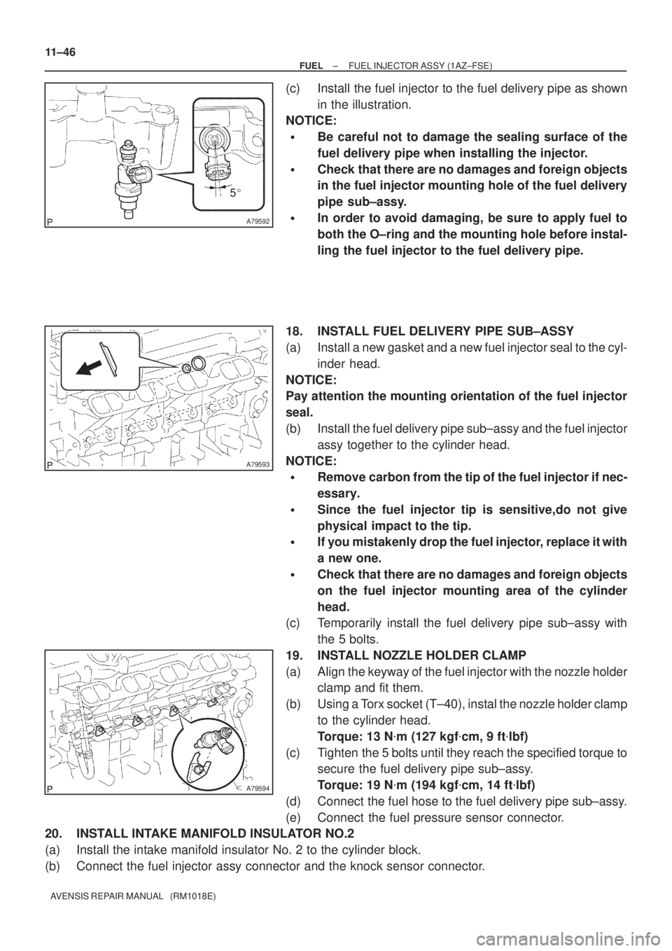
(c) Install the fuel injector to the fuel delivery pipe as shown
in the illustration.
NOTICE:
�Be careful not to damage the sealing surface of the
fuel delivery pipe when installing the injector.
�Check that there are no damages and foreign objects
in the fuel injector mounting hole of the fuel delivery
pipe sub±assy.
�In order to avoid damaging, be sure to apply fuel to
both the O±ring and the mounting hole before instal-
ling the fuel injector to the fuel delivery pipe.
18. INSTALL FUEL DELIVERY PIPE SUB±ASSY
(a) Install a new gasket and a new fuel injector seal to the cyl-
inder head.
NOTICE:
Pay attention the mounting orientation of the fuel injector
seal.
(b) Install the fuel delivery pipe sub±assy and the fuel injector
assy together to the cylinder head.
NOTICE:
�Remove carbon from the tip of the fuel injector if nec-
essary.
�Since the fuel injector tip is sensitive,do not give
physical impact to the tip.
�If you mistakenly drop the fuel injector, replace it with
a new one.
�Check that there are no damages and foreign objects
on the fuel injector mounting area of the cylinder
head.
(c) Temporarily install the fuel delivery pipe sub±assy with
the 5 bolts.
19. INSTALL NOZZLE HOLDER CLAMP
(a) Align the keyway of the fuel injector with the nozzle holder
clamp and fit them.
(b) Using a Torx socket (T±40), instal the nozzle holder clamp
to the cylinder head.
Torque: 13 N�m (127 kgf�cm, 9 ft�lbf)
(c) Tighten the 5 bolts until they reach the specified torque to
secure the fuel delivery pipe sub±assy.
Torque: 19 N�m (194 kgf�cm, 14 ft�lbf)
(d) Connect the fuel hose to the fuel delivery pipe sub±assy.
(e) Connect the fuel pressure sensor connector.
20. INSTALL INTAKE MANIFOLD INSULATOR NO.2
(a) Install the intake manifold insulator No. 2 to the cylinder block.
(b) Connect the fuel injector assy connector and the knock sensor connector.
Page 1875 of 5135
A79595
42135
A79579
±
FUEL FUEL INJECTOR ASSY(1AZ±FSE)
11±47
AVENSIS REPAIR MANUAL (RM1018E)
21.INSTALL SURGE TANK STAY NO.1
(a)Install the surge tank stay No. 1 with the 3 bolts.
Torque: 21 N �m (210 kgf �cm, 15 ft �lbf)
(b)Connect the wire harness to the surge tank stay No. 1.
22.INSTALL INTAKE MANIFOLD
(a)Set a new gasket to the intake manifold.
(b)Temporarily install the intake manifold to the engine assy.
(c)Temporarily install the intake air control valve and a newgasket between the intake manifold and cylinder head,
and then check that the stud bolt holes are aligned.
(d)Connect the 2 vacuum hose and the vacuum sensor con-
nector.
(e)Using a Torx socket, install and tighten the 2 stud bolts to secure the intake manifold, the intake air control valve
and gasket.
Torque: 9.5 N �m (97 kgf �cm, 84 in. �lbf)
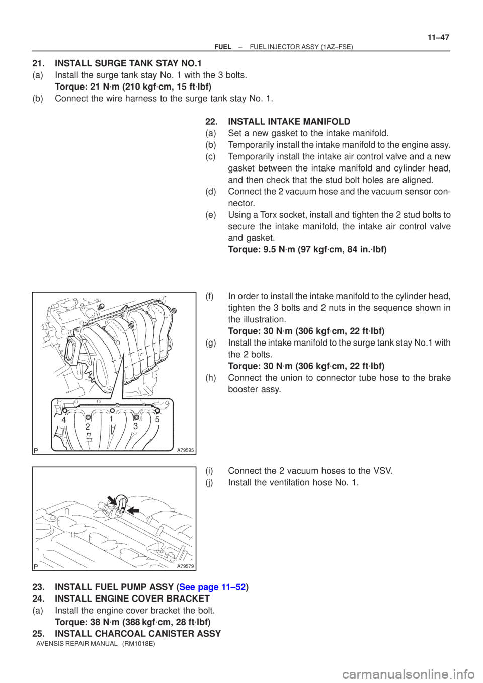
(f)In order to install the intake manifold to the cylinder head, tighten the 3 bolts and 2 nuts in the sequence shown in
the illustration.
Torque: 30 N �m (306 kgf �cm, 22 ft �lbf)
(g)Install the intake manifold to the surge tank stay No.1 with
the 2 bolts.
Torque: 30 N �m (306 kgf �cm, 22 ft �lbf)
(h)Connect the union to connector tube hose to the brake booster assy.
(i)Connect the 2 vacuum hoses to the VSV.
(j)Install the ventilation hose No. 1.
23.INSTALL FUEL PUMP ASSY (See page 11±52)
24. INSTALL ENGINE COVER BRACKET
(a) Install the engine cover bracket the bolt. Torque: 38 N �m (388 kgf �cm, 28 ft �lbf)
25. INSTALL CHARCOAL CANISTER ASSY
Page 1885 of 5135
A75340
Battery4
5
������B12608
A76859
Hand±held Tester
± FUELFUEL SYSTEM (1AZ±FSE)
11±35
AVENSIS REPAIR MANUAL (RM1018E)
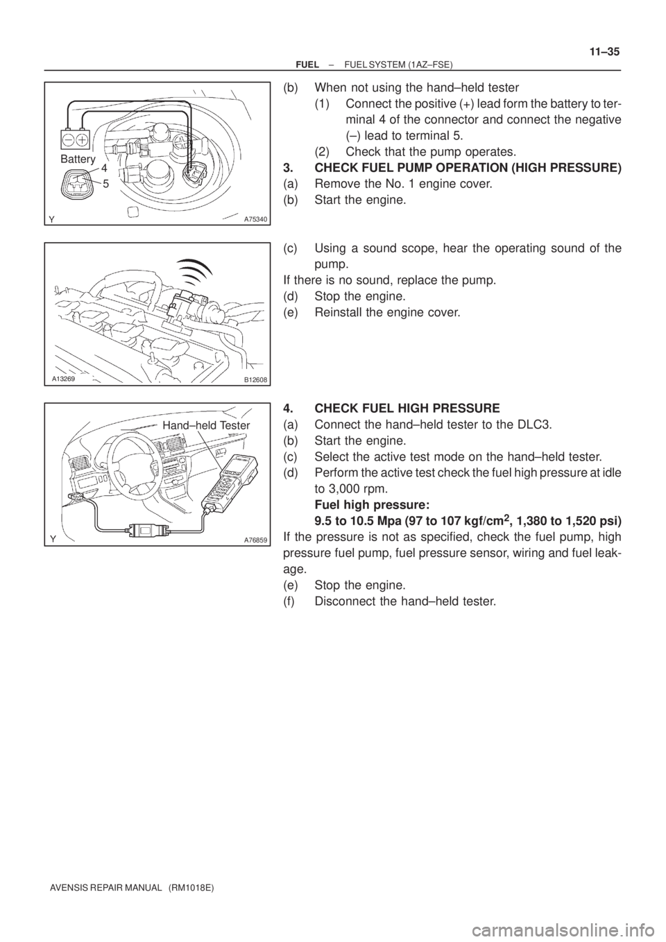
(b) When not using the hand±held tester
(1) Connect the positive (+) lead form the battery to ter-
minal 4 of the connector and connect the negative
(±) lead to terminal 5.
(2) Check that the pump operates.
3. CHECK FUEL PUMP OPERATION (HIGH PRESSURE)
(a) Remove the No. 1 engine cover.
(b) Start the engine.
(c) Using a sound scope, hear the operating sound of the
pump.
If there is no sound, replace the pump.
(d) Stop the engine.
(e) Reinstall the engine cover.
4. CHECK FUEL HIGH PRESSURE
(a) Connect the hand±held tester to the DLC3.
(b) Start the engine.
(c) Select the active test mode on the hand±held tester.
(d) Perform the active test check the fuel high pressure at idle
to 3,000 rpm.
Fuel high pressure:
9.5 to 10.5 Mpa (97 to 107 kgf/cm
2, 1,380 to 1,520 psi)
If the pressure is not as specified, check the fuel pump, high
pressure fuel pump, fuel pressure sensor, wiring and fuel leak-
age.
(e) Stop the engine.
(f) Disconnect the hand±held tester.
Page 1928 of 5135
110CX±02
A75346
A79038
E2S PR2 VCS
VCPR E2
Fuel pressure sensor
A79039Pressure discharge valve
A62162
Vacuum Switch Body
11±56
± FUELFUEL SYSTEM (1CD±FTV)
AVENSIS REPAIR MANUAL (RM1018E)
FUEL SYSTEM (1CD±FTV)
INSPECTION
1. INJECTION OR SUPPLY PUMP ASSY
(a) Resistance inspection.
(1) Using an ohmmeter, measure the resistance be-
tween the terminals.
Resistance: 1.5 to 2.3 � at 20�C (68�F)
2. INJECTOR ASSY
(a) Resistance inspection.
(1) Using an ohmmeter, measure the resistance between the terminals.
Resistance: 0.85 to 1.05 � at 20�C (68�F)
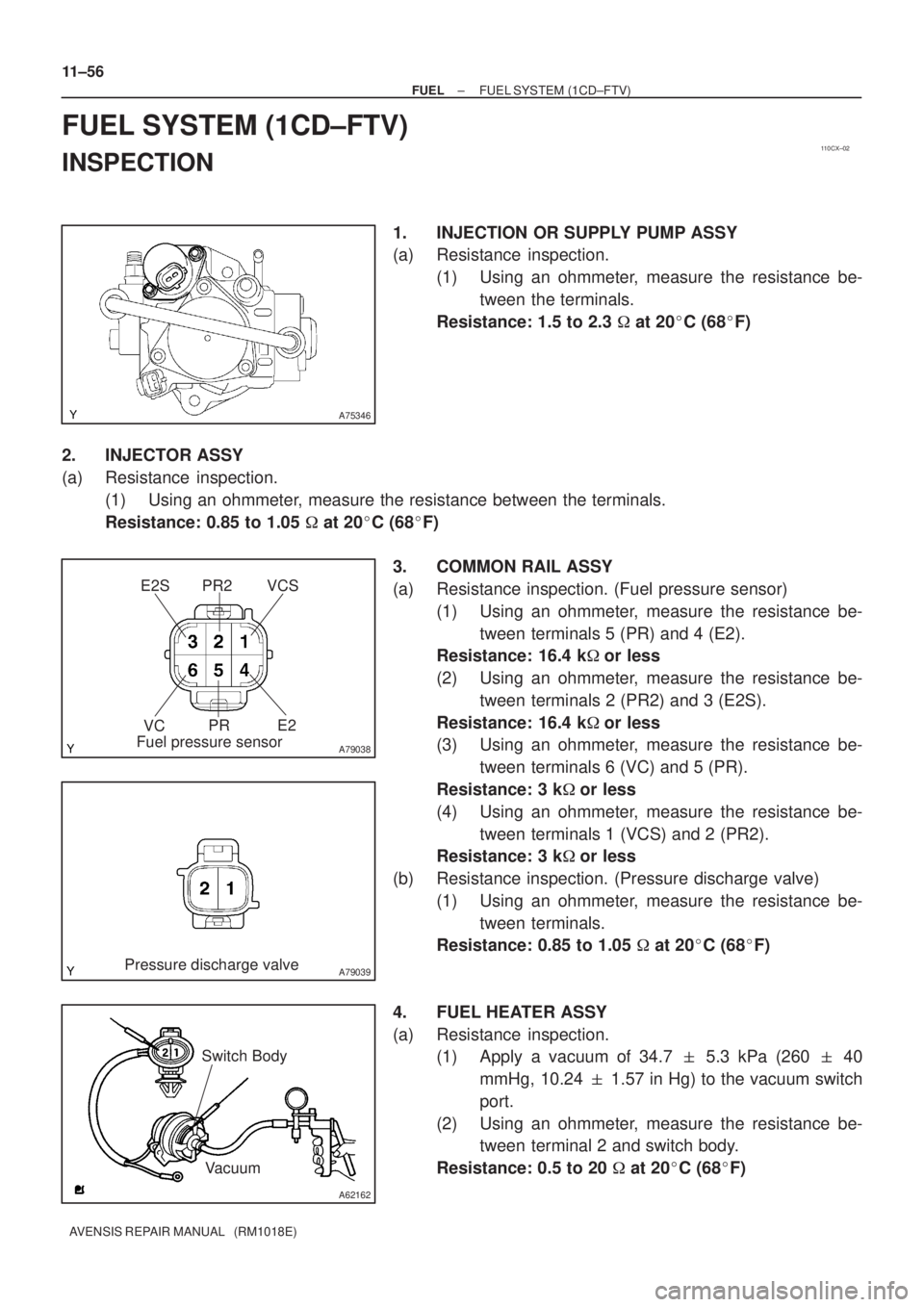
3. COMMON RAIL ASSY
(a) Resistance inspection. (Fuel pressure sensor)
(1) Using an ohmmeter, measure the resistance be-
tween terminals 5 (PR) and 4 (E2).
Resistance: 16.4 k�or less
(2) Using an ohmmeter, measure the resistance be-
tween terminals 2 (PR2) and 3 (E2S).
Resistance: 16.4 k�or less
(3) Using an ohmmeter, measure the resistance be-
tween terminals 6 (VC) and 5 (PR).
Resistance: 3 k�or less
(4) Using an ohmmeter, measure the resistance be-
tween terminals 1 (VCS) and 2 (PR2).
Resistance: 3 k�or less
(b) Resistance inspection. (Pressure discharge valve)
(1) Using an ohmmeter, measure the resistance be-
tween terminals.
Resistance: 0.85 to 1.05 � at 20�C (68�F)
4. FUEL HEATER ASSY
(a) Resistance inspection.
(1) Apply a vacuum of 34.7 � 5.3 kPa (260 � 40
mmHg, 10.24 � 1.57 in Hg) to the vacuum switch
port.
(2) Using an ohmmeter, measure the resistance be-
tween terminal 2 and switch body.
Resistance: 0.5 to 20 � at 20�C (68�F)
Page 1929 of 5135
± FUELFUEL SYSTEM (1CD±FTV)
11±57
AVENSIS REPAIR MANUAL (RM1018E)
5. LEVEL WARNING SWITCH
(a) Continuity inspection.
(1) Using an ohmmeter, check that there is continuity between terminals.
Specified condition:
There is continuity when raising a float.
There is no continuity when letting a float down.
6. FUEL TEMPERATURE SENSOR
(a) Resistance inspection.
(1) Using an ohmmeter, measure the resistance between the terminals.
Resistance:
Approx. 20�C (68�F) 2.21 to 2.69 �
Approx. 80�C (176�F) 0.287 to 0.349 �
Page 1936 of 5135
A77115
Ohmmeter
Resistance
A77116
Ohmmeter
No continuity
A77117
Air E F
A77118
Air E
F
Battery
A64543
+B
Bank 2 Sensor 1:
HT
E1
12±14
± EMISSION CONTROLEMISSION CONTROL SYSTEM (1AZ±FSE)
AVENSIS REPAIR MANUAL (RM1018E)
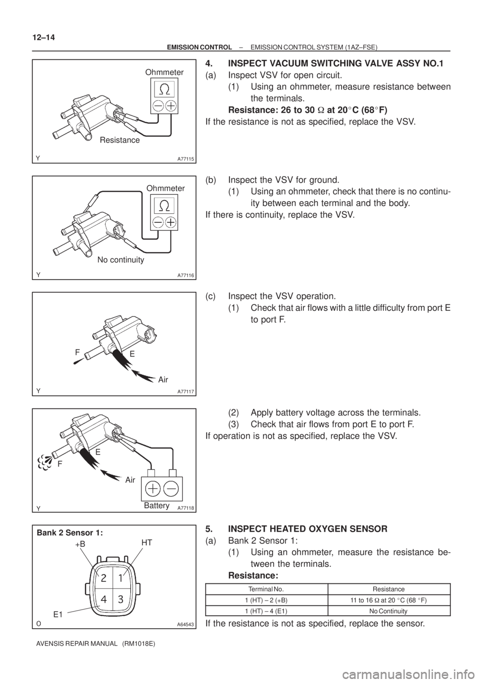
4. INSPECT VACUUM SWITCHING VALVE ASSY NO.1
(a) Inspect VSV for open circuit.
(1) Using an ohmmeter, measure resistance between
the terminals.
Resistance: 26 to 30 � at 20�C (68�F)
If the resistance is not as specified, replace the VSV.
(b) Inspect the VSV for ground.
(1) Using an ohmmeter, check that there is no continu-
ity between each terminal and the body.
If there is continuity, replace the VSV.
(c) Inspect the VSV operation.
(1) Check that air flows with a little difficulty from port E
to port F.
(2) Apply battery voltage across the terminals.
(3) Check that air flows from port E to port F.
If operation is not as specified, replace the VSV.
5. INSPECT HEATED OXYGEN SENSOR
(a) Bank 2 Sensor 1:
(1) Using an ohmmeter, measure the resistance be-
tween the terminals.
Resistance:
Terminal No.Resistance
1 (HT) ± 2 (+B)11 to 16 � at 20 �C (68 �F)
1 (HT) ± 4 (E1)No Continuity
If the resistance is not as specified, replace the sensor.