Page 1796 of 5135

Rotation
Center of
Throttle Link
11�
10±16
±
ENGINE CONTROL SYSTEM THROTTLE BODY ASSY(3ZZ±FE)
AVENSIS REPAIR MANUAL (RM1018E)
9.REMOVE THRO")
A78501
A78503
30� to 45 �
A78469
66.3 mm
(2.610 in.)
Rotation
Center of
Throttle Link
11�
10±16
±
ENGINE CONTROL SYSTEM THROTTLE BODY ASSY(3ZZ±FE)
AVENSIS REPAIR MANUAL (RM1018E)
9.REMOVE THROTTLE POSITION SENSOR
(a)Remove the 2 screws, and then remove the throttle posi- tion sensor.
10.INSTALL THROTTLE POSITION SENSOR
(a)Make sure that the throttle valve is fully closed.
(b)With the throttle position sensor rotated 30 � to 45 � coun-
terclockwise about the fully closed position of the throttle
valve, install the throttle position sensor to the throttle
body.
(c)Rotate the throttle position sensor clockwise and secure it with the 2 screws.
Torque: 2.0 N �m (20 kgf �cm, 18 in. �lbf)
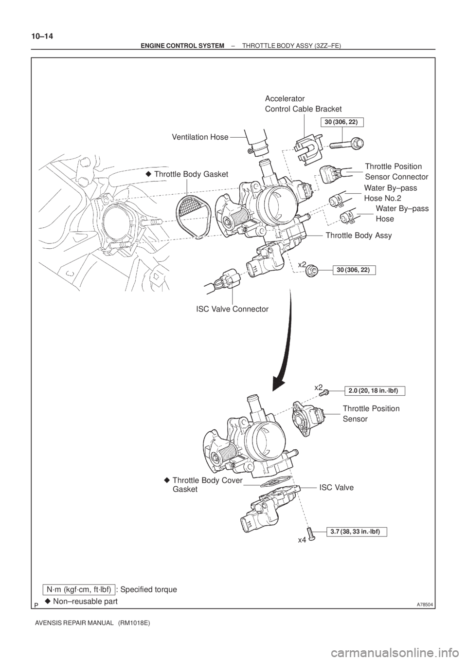
11.INSTALL ISC VALVE
(a)Install a new gasket to the throttle body.
(b)Install the ISC valve with the 4 screws.
Torque: 3.7 N �m (38 kgf �cm, 33 in. �lbf)
12.INSTALL THROTTLE BODY ASSY
(a)Install a new gasket to the intake manifold.
(b)Install the throttle body and the accelerator control brack- et with the bolt and 2 nuts.
Torque: 30 N �m (306 kgf �cm, 22 ft �lbf)
13.INSTALL ACCELERATOR CONTROL CABLE ASSY
(a)Install the accelerator control cable as shown in the il- lustration.
Torque: 13 N �m (129 kgf �cm, 9 ft �lbf)
14.INSTALL AIR CLEANER CAP SUB±ASSY (See page 10±9)
15.INSTALL CYLINDER HEAD COVER NO.2 (See page 10±9)
16.ADD ENGINE COOLANT (See page 16±7)
17.CHECK FOR ENGINE COOLANT LEAKS (See page 16±1)
18. INSTALL ENGINE ROOM COVER SIDE
19. INSTALL RADIATOR SUPPORT OPENING COVER
Page 1798 of 5135
A78504
� Throttle Body Gasket
� Non±reusable part
N´m (kgf´cm, ft´lbf) : Specified torqueISC Valve � Throttle Body Cover
GasketThrottle Position
SensorWater By±pass
Hose Water By±pass
Hose No.2
ISC Valve ConnectorThrottle Body Assy Ventilation Hose
Throttle Position
Sensor Connector
30 (306, 22)
30 (306, 22)
Accelerator
Control Cable Bracket
3.7 (38, 33 in.´lbf)
2.0 (20, 18 in.´lbf)
x2
x2
x4 10±14
± ENGINE CONTROL SYSTEMTHROTTLE BODY ASSY (3ZZ±FE)
AVENSIS REPAIR MANUAL (RM1018E)
Page 1800 of 5135

(b)(c)
(c)
(d)
(e)
(f)
(g)
(h)
Air Cleaner clamp
A78461
A78462
(a)
(b)
(c)
A78463
(d)
(e)
(M/T) 10±10
± ENGINE CONTROL SYSTEMTHROTTLE BODY ASSY (1ZZ±FE)
AVENSIS REPAIR MANUAL (RM1018E)")
A78460
(a)
(b)(c)
(c)
(d)
(e)
(f)
(g)
(h)
Air Cleaner clamp
A78461
A78462
(a)
(b)
(c)
A78463
(d)
(e)
(M/T) 10±10
± ENGINE CONTROL SYSTEMTHROTTLE BODY ASSY (1ZZ±FE)
AVENSIS REPAIR MANUAL (RM1018E)
5. REMOVE AIR CLEANER CAP SUB±ASSY
(a) Disconnect the mass air flow meter connector.
(b) Disconnect the VSV connector.
(c) Remove the 2 wire harness clamps.
(d) Disconnect the fuel vapor feed hose No. 1.
(e) Disconnect the fuel vapor feed hose No. 3.
(f) Remove the accelerator control cable from the accelera-
tor control cable support No. 2.
(g) Loosen the hose clamp.
(h) Raise the air cleaner clamp up, slide it to the air cleaner
cap.
(i) Remove the air cleaner cap together with the air cleaner
hose No. 1.
6. SEPARATE ACCELERATOR CONTROL CABLE ASSY
(a) Loosen the nut and separate the accelerator control
cable.
7. REMOVE THROTTLE BODY ASSY
(a) Disconnect the water by±pass hose.
(b) Disconnect the water by±pass hose No. 2.
(c) Disconnect the ventilation hose.
(d) Disconnect the throttle position sensor connector.
(e) Disconnect the ISC valve connector.
(f) Remove the 3 bolts and 2 nuts, and then remove the
throttle body bracket and the throttle body. (A/T)
(g) Remove the 5 bolts and 2 nuts, and then remove the
throttle body bracket and the throttle body. (M/T)
(h) Remove the gasket from the intake manifold.
Page 1801 of 5135

10±11
AVENSIS REPAIR MANUAL (RM1018E)
8. REMOVE ACCELERATOR CONTROL CABLE
BRACKET
(a) Remove the 2 bolts,")
A78464
A78465
A78466
A78467
30� to 45�
± ENGINE CONTROL SYSTEMTHROTTLE BODY ASSY (1ZZ±FE)
10±11
AVENSIS REPAIR MANUAL (RM1018E)
8. REMOVE ACCELERATOR CONTROL CABLE
BRACKET
(a) Remove the 2 bolts, and then remove the accelerator
control cable bracket.
9. REMOVE ISC VALVE
(a) Remove the 3 screws, and then remove the ISC valve.
(b) Remove the gasket from the throttle body.
10. REMOVE THROTTLE POSITION SENSOR
(a) Remove the 2 screws, and then remove the throttle posi-
tion sensor.
11. INSTALL THROTTLE POSITION SENSOR
(a) Make sure that the throttle valve is fully closed.
(b) With the throttle position sensor rotated 30� to 45� coun-
terclockwise about the fully closed position of the throttle
valve, install the throttle position sensor to the throttle
body.
(c) Rotate the throttle position sensor clockwise and secure
it with the 2 screws.
Torque: 2.0 N�m (20 kgf�cm, 18 in.�lbf)
12. INSTALL ISC VALVE
(a) Install a new gasket to the throttle body.
(b) Install the ISC valve with the 3 screws.
Torque: 3.7 N�m (38 kgf�cm, 33 in.�lbf)
13. INSTALL ACCELERATOR CONTROL CABLE
BRACKET
Torque: 13 N�m (133 kgf�cm, 10 ft�lbf)
Page 1802 of 5135

(c)
A78468
65.1 mm
(2.563 in.)
Rotation
Center of
Throttle Link
18�
10±12
±
ENGINE CONTROL SYSTEM THROTTLE BODY ASSY(1ZZ±FE)
AVENSIS REPAIR MANUAL (RM1018E)
14.INSTALL")
A78463
A
A
A
A
BB
A
(d)
(c)
A78468
65.1 mm
(2.563 in.)
Rotation
Center of
Throttle Link
18�
10±12
±
ENGINE CONTROL SYSTEM THROTTLE BODY ASSY(1ZZ±FE)
AVENSIS REPAIR MANUAL (RM1018E)
14.INSTALL THROTTLE BODY ASSY
(a)Install a new gasket to the intake manifold.
(b)Install the throttle body and the throttle body bracket with the 3 bolts and 2 nuts. (A/T)
Torque:
30 N�m (306 kgf �cm, 22 ft �lbf) for bolt and nut A
(c)Install the throttle body and the throttle body bracket with
the 5 bolts and 2 nuts. (M/T)
Torque:
30 N�m (306 kgf �cm, 22 ft �lbf) for bolt and nut A
13 N �m (133 kgf �cm, 10 ft �lbf) for bolt B
(d)Connect the ISC valve connector.
(e)Connect the throttle position sensor connector.
(f)Connect the ventilation hose.
(g)Connect the water by±pass hose No. 2.
(h)Connect the water by±pass hose.
15.INSTALL ACCELERATOR CONTROL CABLE ASSY
(a)Install the accelerator control cable as shown in the il-
lustration.
Torque: 13 N �m (129 kgf �cm, 9 ft �lbf)
16.INSTALL AIR CLEANER CAP SUB±ASSY Torque: 1.5 N �m (15 kgf �cm, 13 in. �lbf)
17.INSTALL CYLINDER HEAD COVER NO.2 Torque: 7.0 N �m (71 kgf �cm, 62 in. �lbf)
18.ADD ENGINE COOLANT (See page 16±7)
19.CHECK FOR ENGINE COOLANT LEAKS (See page 16±1)
20. INSTALL ENGINE ROOM COVER SIDE
21. INSTALL RADIATOR SUPPORT OPENING COVER
Page 1804 of 5135
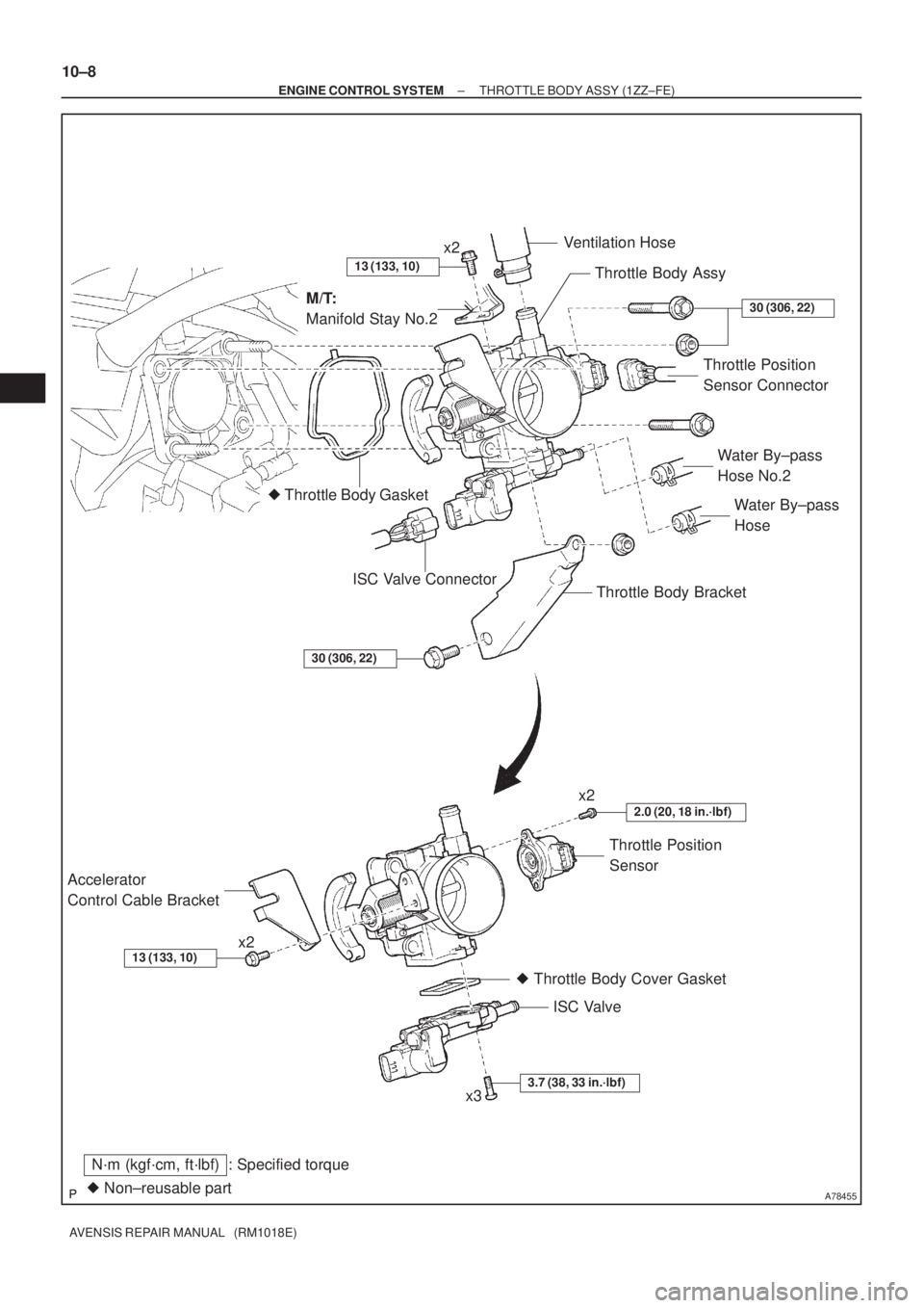
A78455
� Throttle Body Gasket
� Non±reusable part
N´m (kgf´cm, ft´lbf) : Specified torqueISC Valve � Throttle Body Cover Gasket Accelerator
Control Cable BracketThrottle Position
SensorWater By±pass
Hose Water By±pass
Hose No.2
Throttle Body Bracket ISC Valve ConnectorThrottle Body Assy
M/T:
Manifold Stay No.2Ventilation Hose
Throttle Position
Sensor Connector
13 (133, 10)
30 (306, 22)
30 (306, 22)
3.7 (38, 33 in.´lbf)
2.0 (20, 18 in.´lbf)
13 (133, 10)
x3 x2x2 x2 10±8
± ENGINE CONTROL SYSTEMTHROTTLE BODY ASSY (1ZZ±FE)
AVENSIS REPAIR MANUAL (RM1018E)
Page 1806 of 5135

AVEN")
A60621
3ZZ±FE: 1ZZ±FE:
Throttle Stop Screw
Throttle Lever
Throttle Stop Screw
Throttle Lever
No clearance
No clearance
A60551
VTA
E2VC
10±4
± ENGINE CONTROL SYSTEMSFI SYSTEM (1ZZ±FE/3ZZ±FE)
AVENSIS REPAIR MANUAL (RM1018E)
3. INSPECT THROTTLE BODY ASSY
(a) Check throttle body.
(1) Check that throttle valve shaft is not rickety.
(2) Check that each port is not stopped up.
(3) Check that throttle valve opens and closes smooth-
ly.
(4) Check that there is no clearance between the
throttle stop screw and throttle lever at the throttle
closed position.
NOTICE:
Do not adjust the throttle stop screw.
4. INSPECT THROTTLE POSITION SENSOR
(a) Resistance inspection.
(1) Disconnect the throttle position sensor connector.
(2) Using an ohmmeter, measure the resistance be-
tween terminals 1 (VC) and 2 (E2).
Resistance: 2.5 to 6.0 k�
(3) Check the variation resistance between terminals 3
(VTA) and 2 (E2).
Variation in resistance:
The resistance value increases in proportion to the
throttle lever opening value.
HINT:
Throttle valveResistance
Fully open0.2 to 5.7 k�
Fully close2.0 to 10.2 k�
Page 1807 of 5135

TEMPERATURE�C(�F) (32) (68) (104)(140)(176)(212)
A65174
Ohmmeter
A60553
± ENGINE CONTROL SYSTEMSFI SYSTEM (1ZZ±FE/3")
A60552
30
20
10
5
3
2
1
0.5
0.3
0.2
0.1
RESISTANCE k�
±20 0 20 40 60 80 100
(±4)
TEMPERATURE�C(�F) (32) (68) (104)(140)(176)(212)
A65174
Ohmmeter
A60553
± ENGINE CONTROL SYSTEMSFI SYSTEM (1ZZ±FE/3ZZ±FE)
10±5
AVENSIS REPAIR MANUAL (RM1018E)
5. INSPECT ENGINE COOLANT TEMPERATURE
SENSOR
(a) Resistance inspection.
(1) Using an ohmmeter, measure the resistance be-
tween terminals.
Resistance:
2.32 to 2.59 k�at 20�C (68�F)
0.310 to 0.326 k�at 80�C (176�F)
NOTICE:
In case of checking the water temperature sensor in the wa-
ter, be careful not to allow water to go into the terminals,
and after checking, wipe out the sensor.
6. INSPECT KNOCK SENSOR
(a) Using an ohmmeter, measure the resistance between ter-
minals.
Resistance: 120 to 280 k�at 20�C (68�F)
HINT:
If the resistance is not specified, replace the sensor.
7. INSPECT EFI RELAY
(a) Inspect the relay continuity.
(1) Using an ohmmeter, check that there is continuity
between terminals 1 and 2.
Specified condition: Continuity
(2) Check that there is no continuity between terminals
3 and 5.
Specified condition: No continuity
(b) Inspect the relay operation.
(1) Apply battery voltage across terminals 1 and 2.
(2) Using an ohmmeter, check that there is continuity
between terminals 3 and 5.
Specified condition: Continuity