Page 1772 of 5135

2. USING HAND±HELD TESTER
(a) Connect the hand±held tester to the DLC3.
(b) Monitor the ECU data by following the promp")
05±1702
± DIAGNOSTICSCRUISE CONTROL SYSTEM
AVENSIS REPAIR MANUAL (RM1018E)
2. USING HAND±HELD TESTER
(a) Connect the hand±held tester to the DLC3.
(b) Monitor the ECU data by following the prompts on the tester screen.
HINT:
Hand±held tester has a ºSnapshotº function which records the monitored data.
Refer to the hand±held tester operator's manual for further details.
3. DATA LIST
HINT:
From the DATA LIST displayed by the the hand±held tester, you can read the value of the switch, the sensor
and so on without removing parts. Reading the DATA LIST as the first step to troubleshooting is one way
to shorten labor time.
(a) Connect the hand±held tester to the DLC3.
(b) Turn the ignition switch to the ON position.
(c) According to the display on the tester, read the ºDATA LISTº.
ItemMeasurement Item /
Display (Range)Normal ConditionDiagnostic Note
VEHICLE SPDVehicle speed / min.: 0 km/h (0
mph), max.: 255 km/h (158 mph)Actual vehicle speed±
MEMORY SPD
Stored vehicle speed / min.: 36
km/h (22 mph), max.: 200 km/h
(124 mph)
Actual stored vehicle speed±
THROTTLERequired throttle opening angle /
min.: 0�, max.: 125�Actual required throttle opening±
CRUISE CONTROLCruise control system active
condition / ON or OFFON : Cruise control activated
OFF : Cruise control inactivated±
MAIN SW (MAIN)Main SW signal (Main CPU) / ON
or OFFON : Main SW ON (Pushed in)
OFF: Main SW OFF (Pushed out)º3º
MAIN SW (SUB)Main SW signal (Sub CPU) / ON
or OFFON : Main SW ON (Pushed in)
OFF: Main SW OFF (Pushed out)º3º
CCS READY MCruise control system standby
condition (Main CPU) / ON or OFFON ± OFF : Change ON/OFF
each time Main SW is pushed in.º1º
CCS READY SCruise control system standby
condition (Sub CPU) / ON or OFFON ± OFF : Change ON/OFF
each time Main SW is pushed in.º1º
CCS INDICATOR MCruise indicator signal (Main CPU)
/ ON or OFFON : ºCCS READYº ON
OFF : ºCCS READYº OFFº2º
CCS INDICATOR SCruise indicator signal (Sub CPU)
/ ON or OFFON : ºCCS READYº ON
OFF : ºCCS READYº OFFº2º
CANCEL SWCANCEL SW signal / ON or OFFON : CANCEL SW ON
OFF : CANCEL SW OFF±
SET/COAST SWCOAST/SET SW signal / ON or
OFFON : COAST/SET SW ON
OFF : COAST/SET SW OFF±
RES/ACC SWACCEL/RES SW signal / ON or
OFFON : ACCEL/RES SW ON
OFF : ACCEL/RES SW OFF±
STP LIGHT SW2 MStop lamp SW signal (Main CPU) /
ON or OFFON : Brake pedal depressed
OFF : Brake pedal released±
STP LIGHT SW2 SStop lamp SW signal (Sub CPU) /
ON or OFFON : Brake pedal depressed
OFF : Brake pedal released±
Page 1784 of 5135
A77875
(a)
(b)
(c)
(d)
(e)
A81619
A77876
A77877
A77878
10±28
± ENGINE CONTROL SYSTEMTHROTTLE BODY ASSY (1AZ±FE)
AVENSIS REPAIR MANUAL (RM1018E)
7. REMOVE THROTTLE BODY ASSY
(a) Disconnect the throttle position sensor connector.
(b) Disconnect the ISC valve connector.
(c) Disconnect the water by±pass hose No. 2.
(d) Disconnect the water by±pass hose.
(e) Remove the fuel tube from the fuel pipe support.
(f) Remove the 3 bolts, and then remove the fuel pipe sup-
port and the throttle body.
(g) Remove the gasket from the intake manifold.
8. REMOVE FUEL VAPOR FEED HOSE NO.2
(a) Remove the fuel vapor feed hose No. 2 from the throttle
body.
9. REMOVE ISC VALVE
(a) Remove the 3 screws, and then remove the ISC valve.
(b) Remove the gasket from the throttle body.
10. REMOVE THROTTLE POSITION SENSOR
(a) Remove the 2 screws, and then remove the throttle posi-
tion sensor.
Page 1785 of 5135

Rotation
Center of
Throttle Link
±
ENGINE CONTROL SYSTEM THROTTLE BODY ASSY(1AZ±FE)
10±29
AVENSIS REPAIR MANUAL (RM1018E)
11.INSTALL THROTTLE POSITION SEN")
A77879
45�
A77880
83.8 mm
(3.299 in.)
Rotation
Center of
Throttle Link
±
ENGINE CONTROL SYSTEM THROTTLE BODY ASSY(1AZ±FE)
10±29
AVENSIS REPAIR MANUAL (RM1018E)
11.INSTALL THROTTLE POSITION SENSOR
(a)Make sure that throttle valve is fully closed.
(b)With the throttle position sensor rotated 45 � counter-
clockwise about the fully closed position of the throttle
valve, install the throttle position sensor to the throttle
body.
(c)Rotate the throttle position sensor clockwise and secure
it with the 2 screws.
12.INSTALL ISC VALVE
(a)Install a new gasket to the throttle body.
(b)Install the ISC valve with the 3 screws.
13.INSTALL FUEL VAPOR FEED HOSE NO.2
14.INSTALL THROTTLE BODY ASSY
(a)Install a new gasket to the intake manifold.
(b)Install the throttle body and the fuel pipe support with the 3 bolts.
Torque: 30 N �m (306 kgf �cm, 22 ft �lbf)
(c)Install the fuel tube to the fuel pipe support.
(d)Connect the water by±pass hose.
(e)Connect the water by±pass hose No. 2.
(f)Connect the ISC valve connector.
(g)Connect the throttle position sensor connector.
15.INSTALL ACCELERATOR CONTROL CABLE ASSY
(a)Instal the accelerator control cable as shown in the il- lustration.
Torque: 13 N �m (129 kgf �cm, 9 ft �lbf)
16.INSTALL AIR CLEANER CAP SUB±ASSY
17.INSTALL ENGINE COVER SUB±ASSY NO.1 Torque: 7.0 N �m (71 kgf �cm, 62 in. �lbf)
18.ADD ENGINE COOLANT (See page 16±19)
19.CHECK FOR ENGINE COOLANT LEAKS (See page 16±13)
20. INSTALL ENGINE ROOM COVER SIDE
21. INSTALL RADIATOR SUPPORT OPENING COVER
Page 1787 of 5135
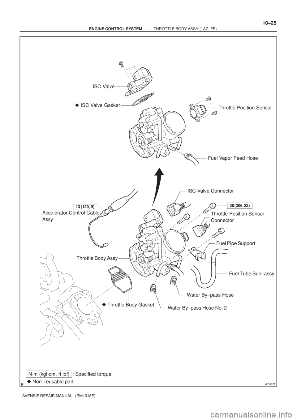
A77871� Non±reusable part
N´m (kgf´cm, ft´lbf) : Specified torqueISC Valve
� ISC Valve Gasket
Fuel Vapor Feed HoseThrottle Position Sensor
Accelerator Control Cable
Assy
� Throttle Body Gasket
Water By±pass Hose No. 2Water By±pass HoseFuel Tube Sub±assy Fuel Pipe Support Throttle Position Sensor
Connector ISC Valve Connector
13 (129, 9)30 (306, 22)
Throttle Body Assy
± ENGINE CONTROL SYSTEMTHROTTLE BODY ASSY (1AZ±FE)
10±25
AVENSIS REPAIR MANUAL (RM1018E)
Page 1789 of 5135

10±21
AVENSIS REPAIR MANUAL (RM1018E)
(b) Adjust the throttle stop screw.
NOTICE:
The throttle stop screw adjusting is very, so adjust")
VTA E2 VC
A35493
± ENGINE CONTROL SYSTEMSFI SYSTEM (1AZ±FE)
10±21
AVENSIS REPAIR MANUAL (RM1018E)
(b) Adjust the throttle stop screw.
NOTICE:
The throttle stop screw adjusting is very, so adjust it only
when the adjusting is really needed.
(1) Loosen the locknut and loosen the screw until it de-
taches the lever.
(2) Confirm that the throttle vale is fully closed.
(3) After the screw touches the lever, tighten it by 1/4
revolution additionally and tighten the lock nut.
(4) Seal the lock nut with yellow paint.
(5) Check that the throttle position sensor operates
normally.
4. INSPECT THROTTLE POSITION SENSOR
(a) Resistance inspection.
(1) Disconnect the throttle position sensor connector.
(2) Using an ohmmeter, measure the resistance be-
tween terminals VC and E2.
Resistance: 2.5 to 5.0 k�
(3) Check the change of resistance between terminals
VTA and E2.
Change of resistance:
The resistance value increases in proportion to the
throttle lever opening value.
HINT:
Throttle valveResistance
Fully close0.2 to 5.7 k�
Fully open2.0 to 10.2 k�
Page 1790 of 5135

RESISTANCE k�
30
20
10
5
2
1
0.5
0.3
0.2
0.13
±20 0 20 40 60 80 100
(±4)(32) (80) (140)(104) (212)
(176)
A50371
A65174
Ohmmeter
E34090
10±22
± ENGINE CONTROL SYSTEMSFI SYSTEM (1A")
TEMPERATURE�C(�F)
RESISTANCE k�
30
20
10
5
2
1
0.5
0.3
0.2
0.13
±20 0 20 40 60 80 100
(±4)(32) (80) (140)(104) (212)
(176)
A50371
A65174
Ohmmeter
E34090
10±22
± ENGINE CONTROL SYSTEMSFI SYSTEM (1AZ±FE)
AVENSIS REPAIR MANUAL (RM1018E)
5. INSPECT ENGINE COOLANT TEMPERATURE
SENSOR
(a) Resistance inspection.
(1) Using an ohmmeter, measure the resistance be-
tween each terminal.
Resistance:
Approx. 20�C (68�F) 2.32 to 2.59k�
Approx. 80�C (176�F) 0.310 to 0.326k�
NOTICE:
In case of checking the water temperature sensor in the wa-
ter, be careful not to allow water to go into the terminals,
and after checking, wipe out the sensor.
6. INSPECT KNOCK SENSOR
(a) Using an ohmmeter, measure the resistance between ter-
minals.
Resistance: 120 to 280 k�at 20�C (68�F)
HINT:
If the resistance is not specified, replace the sensor.
7. INSPECT EFI RELAY
(a) Inspect the relay continuity.
(1) Using an ohmmeter, check that there is continuity
between terminals 1 and 2.
Specified condition: Continuity
(2) Check that there is no continuity between terminals
3 and 5.
Specified condition: No continuity
(b) Inspect the relay operation.
(1) Apply battery voltage across terminals 1 and 2.
(2) Using an ohmmeter, check that there is continuity
between terminals 3 and 5.
Specified condition: Continuity
Page 1794 of 5135
100FF±01
A78505
A78502
A78506
Upper
30�30�
± ENGINE CONTROL SYSTEMKNOCK SENSOR (1ZZ±FE/3ZZ±FE)
10±17
AVENSIS REPAIR MANUAL (RM1018E)
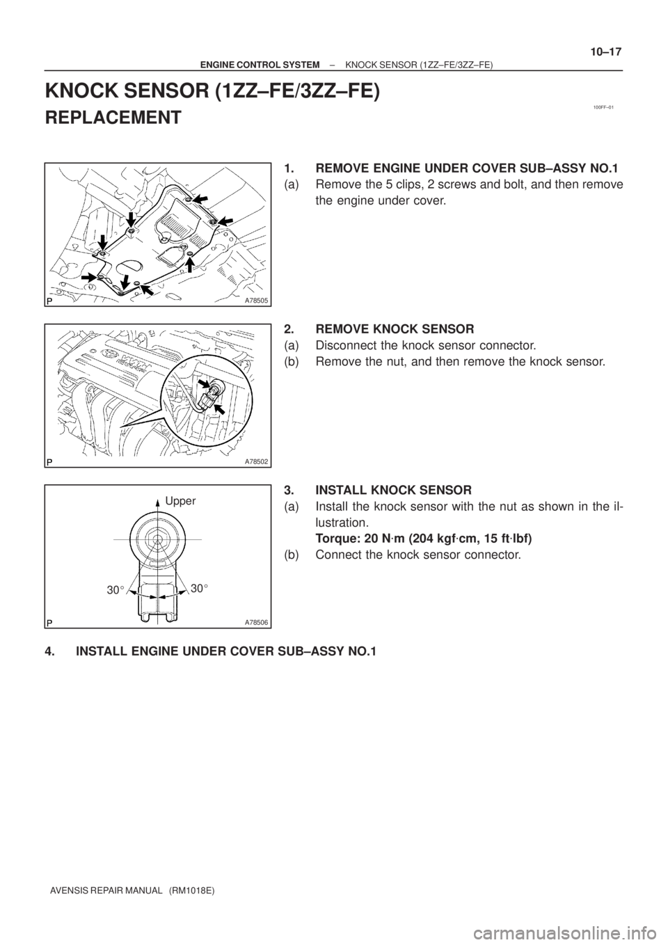
KNOCK SENSOR (1ZZ±FE/3ZZ±FE)
REPLACEMENT
1. REMOVE ENGINE UNDER COVER SUB±ASSY NO.1
(a) Remove the 5 clips, 2 screws and bolt, and then remove
the engine under cover.
2. REMOVE KNOCK SENSOR
(a) Disconnect the knock sensor connector.
(b) Remove the nut, and then remove the knock sensor.
3. INSTALL KNOCK SENSOR
(a) Install the knock sensor with the nut as shown in the il-
lustration.
Torque: 20 N�m (204 kgf�cm, 15 ft�lbf)
(b) Connect the knock sensor connector.
4. INSTALL ENGINE UNDER COVER SUB±ASSY NO.1
Page 1795 of 5135

(b)
(c)
A78499
(d)
(e)
A78500
±
ENGINE CONTROL SYSTEM THROTTLE BODY ASSY(3ZZ±FE)
10±15
AVENSIS REPAIR MANUAL (RM1018E)
Removal & Installation and Disassembly & Reassem")
100FE±01
A78497
A78498
(a)
(b)
(c)
A78499
(d)
(e)
A78500
±
ENGINE CONTROL SYSTEM THROTTLE BODY ASSY(3ZZ±FE)
10±15
AVENSIS REPAIR MANUAL (RM1018E)
Removal & Installation and Disassembly & Reassembly
1.REMOVE RADIATOR SUPPORT OPENING COVER (See page 10±9)
2.REMOVE ENGINE ROOM COVER SIDE (See page 10±9)
3.DRAIN ENGINE COOLANT (See page 16±7)
4.REMOVE CYLINDER HEAD COVER NO.2 (See page 10±9)
5.REMOVE AIR CLEANER CAP SUB±ASSY (See page 10±9)
6. SEPARATE ACCELERATOR CONTROL CABLE ASSY
(a) Loosen the nut and separate the accelerator controlcable.
7. REMOVE THROTTLE BODY ASSY
(a) Disconnect the ventilation hose.
(b) Disconnect the water by±pass hose.
(c) Disconnect the water by±pass hose No. 2.
(d) Disconnect the throttle position sensor.
(e) Disconnect the ISC valve connector.
(f) Remove the bolt and 2 nuts, and then remove the acceler- ator control bracket and the throttle body.
(g) Remove the gasket from the intake manifold.
8. REMOVE ISC VALVE
(a) Remove the 4 screws, and then remove the ISC valve.
(b) Remove the gasket from the throttle body.

(b)
(c)
(d)
(e)
A81619
A77876
A77877
A77878
10±28
± ENGINE CONTROL SYSTEMTHROTTLE BODY ASSY (1AZ±FE)
AVENSIS REPAIR MANUAL (RM1018E)
7. REMOVE THROTTLE BODY ASSY
(a) Disconnect the thr")