Page 1524 of 5135
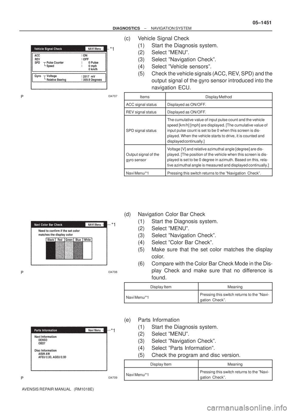
I34707
*1
I34708
*1
I34709
*1
± DIAGNOSTICSNAVIGATION SYSTEM
05±1451
AVENSIS REPAIR MANUAL (RM1018E)
(c) Vehicle Signal Check
(1) Start the Diagnosis system.
(2) Select ºMENUº.
(3) Select ºNavigation Checkº.
(4) Select ºVehicle sensorsº.
(5) Check the vehicle signals (ACC, REV, SPD) and the
output signal of the gyro sensor introduced into the
navigation ECU.
ItemsDisplay Method
ACC signal statusDisplayed as ON/OFF.
REV signal statusDisplayed as ON/OFF.
SPD signal status
The cumulative value of input pulse count and the vehicle
speed [km/h] [mph] are displayed. [The cumulative value of
input pulse count is set to be 0 when this screen is dis-
played. When the vehicle starts to drive, it is counted and
displayed continually.]
Output signal of the
gyro sensor
Voltage [V] and relative azimuthal angle [degree] are dis-
played. [The position of the vehicle when this screen is dis-
played is set to be 0 degree in azimuth. Based on this, rela-
tive azimuthal angle is measured and displayed continually.]
Navi Menu/*1Pressing this switch returns to the ºNavigation Checkº.
(d) Navigation Color Bar Check
(1) Start the Diagnosis system.
(2) Select ºMENUº.
(3) Select ºNavigation Checkº.
(4) Select ºColor Bar Checkº.
(5) Make sure that the set color matches the display
color.
(6) Compare with the Color Bar Check Mode in the Dis-
play Check and make sure that no difference is
found.
Display ItemMeaning
Navi Menu/*1Pressing this switch returns to the ºNavi-
gation Checkº.
(e) Parts Information
(1) Start the Diagnosis system.
(2) Select ºMENUº.
(3) Select ºNavigation Checkº.
(4) Select ºParts Informationº.
(5) Check the program and disc version.
Display ItemMeaning
Navi Menu/*1Pressing this switch returns to the ºNavi-
gation Checkº.
Page 1531 of 5135
I34624
Front Seat Inner
Belt Assy LH
Occupant Detection Sensor
Front Seat Inner
Belt Assy RH
Passenger's Seat belt
Warning LampDriver Side R/BAccessary Meter
Combination Meter Assy
Driver Side J/B
Fuse Block
Center J/B
± DIAGNOSTICSCOMBINATION METER
05±1501
AVENSIS REPAIR MANUAL (RM1018E)
Page 1535 of 5135
Terminal No.
Wire harness side
Turn Signal Flasher Relay
Skid Control ECU with Actuator Brake Fluid Level Warning Switch
Engine ECU
Oil Pressure Switch
DOME Fuse Headlight Beam Level Control ECU
Skid Control ECU with Actuator
Skid Control ECU with Actuator Turn Signal Flasher Relay Engine ECU ± Multi Display RAD No.1 Fuse
GND
EMPS ECU
TAIL Fuse
Skid Control ECU with Actuator Fuel Sensor Gauge
Skid Control ECU with Actuator
± GND
Rear Fog Light Relay Front Fog Light Relay Multi Display Fuse Filter Warning Switch (*1)
IGN Fuse Fuel Sender Gauge
Engine Oil Level Sensor Security ECU Ambient Temp. Sensor
4P OUT (Other Parts) H±HI RH Fuse/H±LP RH Fuse 1
2
3
4
5
6
7
8
9
10
11
12
13
14
15
16
17
18
19
201
2
3
4
5
6
7
8
9
10
11
12
13
14
15
16
17
18
C10
Airbag Sensor Assembly GND
GAUGE1 Fuse Skid Control ECU with Actuator
C11Engine ECU
Integration Relay
21
22
*1: 1CD±FTVAmbient Temp. Sensor
± DIAGNOSTICSCOMBINATION METER
05±1505
AVENSIS REPAIR MANUAL (RM1018E)
Page 1536 of 5135
056Q9±02
Ignition SW
ODO/TRIP SW
Driver's Seat BeltON
OFF
6s
10s10s
ON
OFF
Unfastened
Fastened
± DIAGNOSTICSCOMBINATION METER
05±1499
AVENSIS REPAIR MANUAL (RM1018E)
PRE±CHECK
1. DATA LIST
According to the DATA LIST displayed by the hand±held tester, you can read the value of the switch, sensor,
actuator and so on without parts removal. Reading the DATA LIST as the first step of troubleshooting is one
method to shorten work time.
(a) Warm up the engine.
(b) Turn the ignition switch to OFF.
(c) Connect the hand±held tester to DLC3.
(d) Turn the ignition switch to ON.
(e) Operate the hand±held tester according to the steps on the display and select ºDATA LISTº.
ALL(ECM):
ItemMeasurement Item/
Range (Display)Normal ConditionDiagnostic Note
VEHICLE SPEEDVehicle speed / Min.: 0 km/h,
Max.: 255 km/hAlmost same at the meter speed
(When driving)±
ENGINE SPEEDEngine speed / Min.: 0 rpm, Max.:
16,383 rpmAlmost same at the meter rpm
(When engine is running)±
COOLANT TEMPCoolant Temperature / Min.:
±40�C, Max.: 140�CAfter warming up: 80 ± 95�C (176
± 203���If the value is º±40 �Cº or º140
�Cº, sensor circuit is open or
shorted.
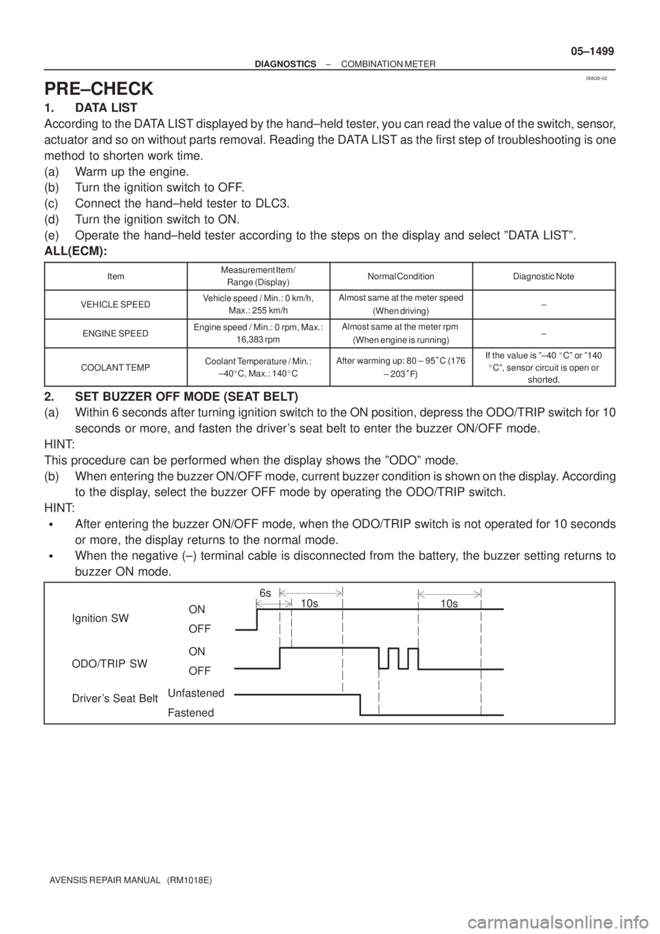
2. SET BUZZER OFF MODE (SEAT BELT)
(a) Within 6 seconds after turning ignition switch to the ON position, depress the ODO/TRIP switch for 10
seconds or more, and fasten the driver's seat belt to enter the buzzer ON/OFF mode.
HINT:
This procedure can be performed when the display shows the ºODOº mode.
(b) When entering the buzzer ON/OFF mode, current buzzer condition is shown on the display. According
to the display, select the buzzer OFF mode by operating the ODO/TRIP switch.
HINT:
�After entering the buzzer ON/OFF mode, when the ODO/TRIP switch is not operated for 10 seconds
or more, the display returns to the normal mode.
�When the negative (±) terminal cable is disconnected from the battery, the buzzer setting returns to
buzzer ON mode.
Page 1545 of 5135
I34724
Neutral Start SW (*4)
Back±up Light SW (*5)21
N1B1
(*4)(*5) 5
IK1
R±YR±Y (*3)R±Y (*1)
R±Y (*2)R±Y (*2)AA
CC
J5
J/C
J22
J/C 14
N3
Navigation ECU
REV
*1: LHD
*2: RHD
*3: LHD Except 1ZZ±FE, 3ZZ±FE *4: A/T
*5: M/T
I32703REV
N3
05±1490
±
DIAGNOSTICS NAVIGATION SYSTEM
AVENSIS REPAIR MANUAL (RM1018E)
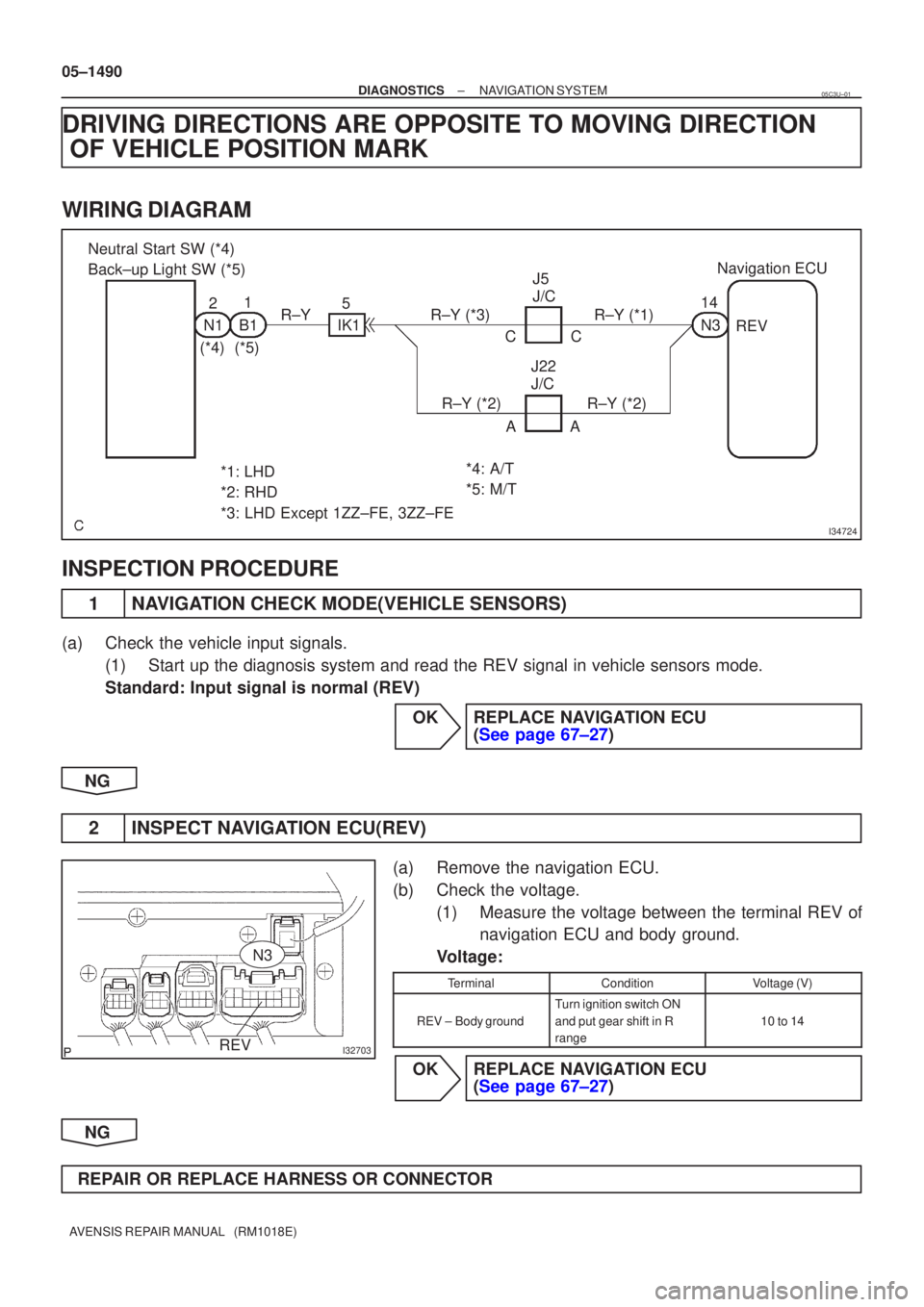
DRIVING DIRECTIONS ARE OPPOSITE TO MOVING DIRECTION OF VEHICLE POSITION MARK
WIRING DIAGRAM
INSPECTION PROCEDURE
1NAVIGATION CHECK MODE(VEHICLE SENSORS)
(a)Check the vehicle input signals.
(1)Start up the diagnosis system and read the REV signal in vehicle sensors\
mode.
Standard: Input signal is normal (REV)
OKREPLACE NAVIGATION ECU (See page 67±27)
NG
2INSPECT NAVIGATION ECU(REV)
(a)Remove the navigation ECU.
(b)Check the voltage. (1)Measure the voltage between the terminal REV ofnavigation ECU and body ground.
Voltage:
TerminalConditionVoltage (V)
REV ±Body ground
Turn ignition switch ON
and put gear shift in R
range
10 to 14
OKREPLACE NAVIGATION ECU (See page 67±27)
NG
REPAIR OR REPLACE HARNESS OR CONNECTOR
05C3U±01
Page 1546 of 5135
I34722
Combination MeterNavigation ECU
18
C11 V±W J/C
HH J10 (*1)
J20 (*2)
V±W
*1: LHD
*2: RHD 5
N3SPD
05±1488
±
DIAGNOSTICS NAVIGATION SYSTEM
AVENSIS REPAIR MANUAL (RM1018E)
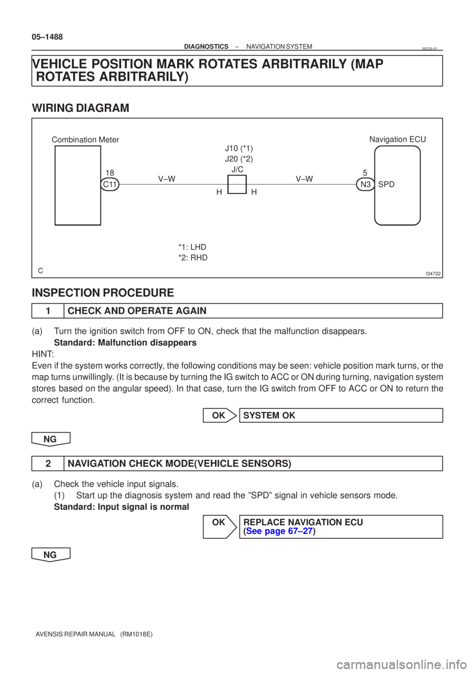
VEHICLE POSITION MARK ROTATES ARBITRARILY (MAP ROTATES ARBITRARILY)
WIRING DIAGRAM
INSPECTION PROCEDURE
1CHECK AND OPERATE AGAIN
(a)Turn the ignition switch from OFF to ON, check that the malfunction disappea\
rs.
Standard: Malfunction disappears
HINT:
Even if the system works correctly, the following conditions may be seen: vehicle position mark turns, or the
map turns unwillingly. (It is because by turning the IG switch to ACC or ON during turning, \
navigation system
stores based on the angular speed). In that case, turn the IG switch from OFF to ACC\
or ON to return the
correct function.
OKSYSTEM OK
NG
2NAVIGATION CHECK MODE(VEHICLE SENSORS)
(a)Check the vehicle input signals. (1)Start up the diagnosis system and read the ºSPDº signal in vehicle\
sensors mode.
Standard: Input signal is normal
OKREPLACE NAVIGATION ECU (See page 67±27)
NG
05C3S±01
Page 1550 of 5135
I32703
SPDGND1N3
9 to14 V
0 Turn the wheel
05±1486
±
DIAGNOSTICS NAVIGATION SYSTEM
AVENSIS REPAIR MANUAL (RM1018E)
4NAVIGATION CHECK MODE(VEHICLE SENSORS)
(a)Check the vehicle input signals. (1)Start up the diagnosis system and read the SPEED signal in vehicle signa\
l check mode.
Standard: Input signal is normal (SPEED)
NGGo to step 6
OK
5CHECK AND OPERATE AGAIN
Standard: Normally returns OKSYSTEM OK
NG
REPLACE NAVIGATION ECU (See page 67±27)
6INSPECT NAVIGATION ECU(SPD, GND1)
(a)Remove the navigation ECU.
(b)Check the voltage. (1)Shift the shift lever to neutral.
(2)Jack up either one of the front wheels.
(3)Turn ignition switch ON.
(4)Measure the voltage between the terminal SPD andGND1 of navigation ECU when the front wheels are
turned slowly.
Standard: Voltage is pulsed.
OKREPLACE NAVIGATION ECU (See page 67±27)
NG
REPAIR OR REPLACE HARNESS OR CONNECTOR
Page 1561 of 5135
± DIAGNOSTICSPOWER DOOR LOCK CONTROL SYSTEM
05±1537
AVENSIS REPAIR MANUAL (RM1018E)
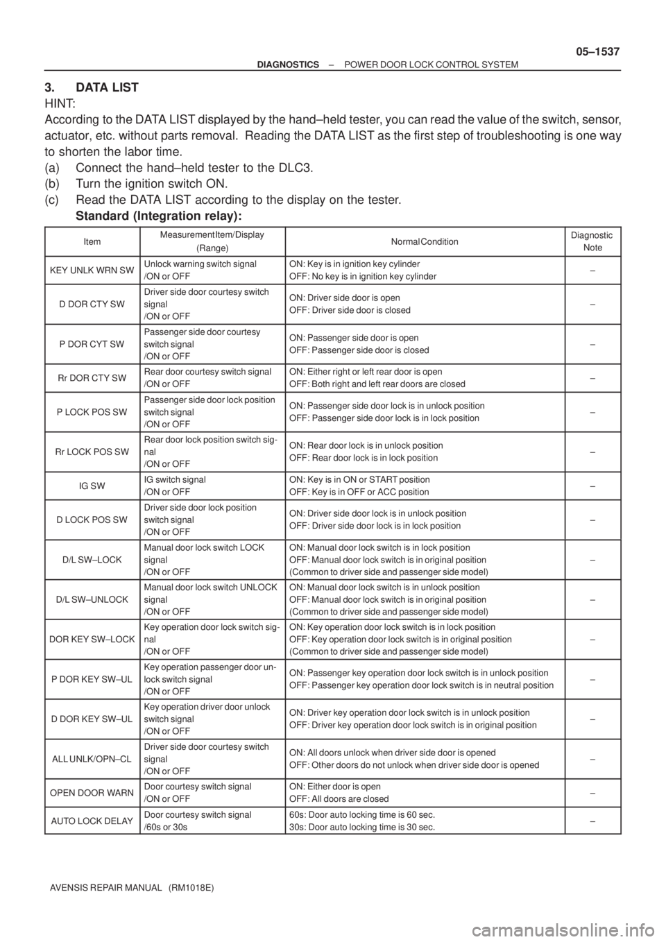
3. DATA LIST
HINT:
According to the DATA LIST displayed by the hand±held tester, you can read the value of the switch, sensor,
actuator, etc. without parts removal. Reading the DATA LIST as the first step of troubleshooting is one way
to shorten the labor time.
(a) Connect the hand±held tester to the DLC3.
(b) Turn the ignition switch ON.
(c) Read the DATA LIST according to the display on the tester.
Standard (Integration relay):
ItemMeasurement Item/Display
(Range)Normal ConditionDiagnostic
Note
KEY UNLK WRN SWUnlock warning switch signal
/ON or OFFON: Key is in ignition key cylinder
OFF: No key is in ignition key cylinder±
D DOR CTY SW
Driver side door courtesy switch
signal
/ON or OFFON: Driver side door is open
OFF: Driver side door is closed±
P DOR CYT SW
Passenger side door courtesy
switch signal
/ON or OFFON: Passenger side door is open
OFF: Passenger side door is closed±
Rr DOR CTY SWRear door courtesy switch signal
/ON or OFFON: Either right or left rear door is open
OFF: Both right and left rear doors are closed±
P LOCK POS SW
Passenger side door lock position
switch signal
/ON or OFFON: Passenger side door lock is in unlock position
OFF: Passenger side door lock is in lock position±
Rr LOCK POS SW
Rear door lock position switch sig-
nal
/ON or OFFON: Rear door lock is in unlock position
OFF: Rear door lock is in lock position±
IG SWIG switch signal
/ON or OFFON: Key is in ON or START position
OFF: Key is in OFF or ACC position±
D LOCK POS SW
Driver side door lock position
switch signal
/ON or OFFON: Driver side door lock is in unlock position
OFF: Driver side door lock is in lock position±
D/L SW±LOCK
Manual door lock switch LOCK
signal
/ON or OFFON: Manual door lock switch is in lock position
OFF: Manual door lock switch is in original position
(Common to driver side and passenger side model)
±
D/L SW±UNLOCK
Manual door lock switch UNLOCK
signal
/ON or OFFON: Manual door lock switch is in unlock position
OFF: Manual door lock switch is in original position
(Common to driver side and passenger side model)
±
DOR KEY SW±LOCK
Key operation door lock switch sig-
nal
/ON or OFFON: Key operation door lock switch is in lock position
OFF: Key operation door lock switch is in original position
(Common to driver side and passenger side model)
±
P DOR KEY SW±UL
Key operation passenger door un-
lock switch signal
/ON or OFFON: Passenger key operation door lock switch is in unlock position
OFF: Passenger key operation door lock switch is in neutral position±
D DOR KEY SW±UL
Key operation driver door unlock
switch signal
/ON or OFFON: Driver key operation door lock switch is in unlock position
OFF: Driver key operation door lock switch is in original position±
ALL UNLK/OPN±CL
Driver side door courtesy switch
signal
/ON or OFFON: All doors unlock when driver side door is opened
OFF: Other doors do not unlock when driver side door is opened±
OPEN DOOR WARNDoor courtesy switch signal
/ON or OFFON: Either door is open
OFF: All doors are closed±
AUTO LOCK DELAYDoor courtesy switch signal
/60s or 30s60s: Door auto locking time is 60 sec.
30s: Door auto locking time is 30 sec.±