Page 1446 of 5135
������������H42844
Airbag
Sensor
Assy
Center Knee Squib
DK± DK+
A
B
C D E
F
± DIAGNOSTICSSUPPLEMENTAL RESTRAINT SYSTEM
05±1375
AVENSIS REPAIR MANUAL (RM1018E)
INSPECTION PROCEDURE
1 CHECK CONNECTOR
(a) Turn the ignition switch to the LOCK position.
(b) Disconnect the negative (±) terminal cable from the battery, and wait for at least 90 seconds.
(c) Disconnect the connectors from the airbag sensor assy center and the instrument panel airbag assy.
(d) Check that the instrument panel wire connector (on the instrument panel airbag assy side) is not dam-
aged.
OK:
The lock button is not disengaged, or the claw of the lock is not deformed or damaged.
NG REPAIR OR REPLACE INSTRUMENT PANEL
WIRE
OK
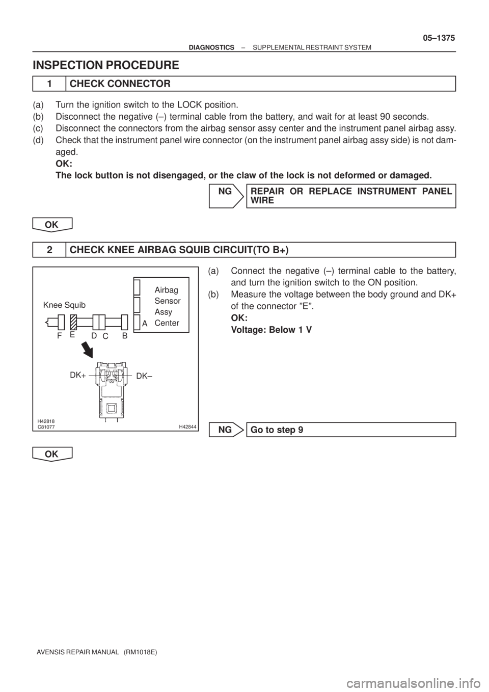
2 CHECK KNEE AIRBAG SQUIB CIRCUIT(TO B+)
(a) Connect the negative (±) terminal cable to the battery,
and turn the ignition switch to the ON position.
(b) Measure the voltage between the body ground and DK+
of the connector ºEº.
OK:
Voltage: Below 1 V
NG Go to step 9
OK
Page 1447 of 5135
������������H42844
Airbag
Sensor
Assy
Center Knee Squib
DK± DK+
A
B
C D E
F
������������H42844
Airbag
Sensor
Assy
Center Knee Squib
DK± DK+
A
B
C D E
F
05±1376
± DIAGNOSTICSSUPPLEMENTAL RESTRAINT SYSTEM
AVENSIS REPAIR MANUAL (RM1018E)
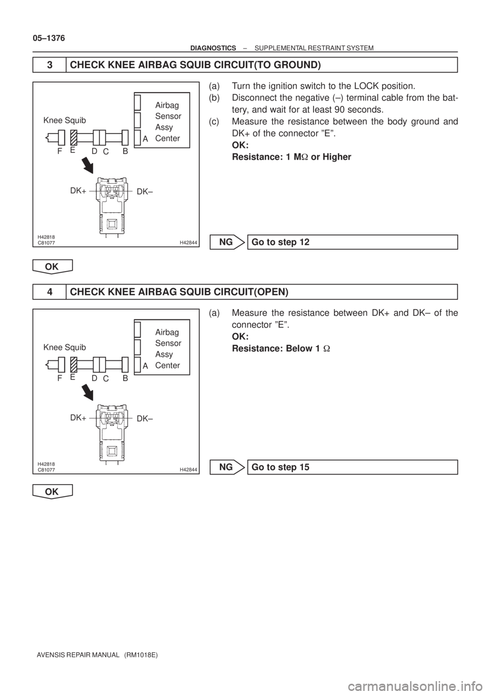
3 CHECK KNEE AIRBAG SQUIB CIRCUIT(TO GROUND)
(a) Turn the ignition switch to the LOCK position.
(b) Disconnect the negative (±) terminal cable from the bat-
tery, and wait for at least 90 seconds.
(c) Measure the resistance between the body ground and
DK+ of the connector ºEº.
OK:
Resistance: 1 M� or Higher
NG Go to step 12
OK
4 CHECK KNEE AIRBAG SQUIB CIRCUIT(OPEN)
(a) Measure the resistance between DK+ and DK± of the
connector ºEº.
OK:
Resistance: Below 1 �
NG Go to step 15
OK
Page 1448 of 5135

�� � � ��\b\bH42844
Airbag
Sensor
Assy
Center
Knee Squib
DK±
DK+
A
B
C
D
E
F
�� �
�����\f�����H42845
Airbag
Sensor
Assy
Center
Knee Squib
DLC3
CG TC DTC B1650/B1651/
B1652/B1653/49
C
D
E
F
±
DIAGNOSTICS SUPPLEMENTAL RESTRAINT SYSTEM
05±1377
AVENSIS REPAIR MANUAL (RM1018E)
5CHECK KNEE AIRBAG SQUIB CIRCUIT(SHORT)
(a)Release the activation prevention mechanism built in the
connector ºBº (See page 05±1184).
(b)Measure the resistance between DK+ and DK± of the connector ºEº.
OK:
Resistance 1 M � or Higher
NGGo to step 17
OK
6CHECK AIR BAG SENSOR ASSY CENTER
(a)Connect the connectors to the airbag sensor assy center and the instrument panel airbag assy.
(b)Connect the negative (±) terminal cable to the battery, and wait for at least 2 seconds.
(c)Turn the ignition switch to the ON position, and wait for at
least 10 seconds.
(d)Clear the stored DTCs in the memory (See page 05±1184).
(e) Turn the ignition switch to the LOCK position.
(f) Turn the ignition switch to the ON position, and wait for at least 10 seconds.
(g)Check the DTCs (See page 05±1184). OK:
DTC B1650/49, B1651/49, B1652/49 or B1653/49 are
not output.
HINT:
Codes other than code B1650/49, B1651/49, B1652/49 or
B1683/49 may be output at this time, but they are not related
to this check.
NG Go to step 7
OK
USE SIMULATION METHOD TO CHECK
Page 1449 of 5135

���\b� ������
�����H42845
Airbag
Sensor
Assy
Center
Knee Squib
DLC3
CG TC DTC B1650/B1651/
B1652/B1653/49
C
D
E
F
05±1378
±
DIAGNOSTICS SUPPLEMENTAL RESTRAINT SYSTEM
AVENSIS REPAIR MANUAL (RM1018E)
7REPLACE AIR BAG SENSOR ASSY CENTER
(a)Turn the ignition switch to the LOCK position.
(b)Disconnect the negative (±) terminal cable from the battery, and wait for at least 90 seconds.
(c)Replace the airbag sensor assy center (See page 60±62).
8RECHECK DTC
(a)Connect the negative (±) terminal cable to the battery, and wait for at least 2 seconds.
(b)Turn the ignition switch to the ON position, and wait for at least 10 seconds.
(c)Clear the stored DTCs in the memory (See page
05±1184).
(d) Turn the ignition switch to the LOCK position.
(e) Turn the ignition switch to the ON position, and wait for at least 10 seconds.
(f)Check the DTCs (See page 05±1184). OK:
DTC B1650/49, B1651/49, B1652/49 or B1653/49 are
not output.
HINT:
Codes other than code B1650/49, B1651/49, B1652/49 or
B1683/49 may be output at this time, but they are not related
to this check.
NG REPLACE INSTRUMENT PANEL AIR BAG ASSY
OK
END
Page 1450 of 5135

�����������H42846
Airbag
Sensor
Assy
Center Knee Squib
DK± DK+Floor Wire
No.2 Instrument
Panel Wire
A
B C
D E F
����� �����H42847
Airbag
Sensor
Assy
Center Knee Squib
DK± DK+Floor Wire No.2
A
B C
D E F
± DIAGNOSTICSSUPPLEMENTAL RESTRAINT SYSTEM
05±1379
AVENSIS REPAIR MANUAL (RM1018E)
9 CHECK INSTRUMENT PANEL WIRE(TO B+)
(a) Turn the ignition switch to the LOCK position.
(b) Disconnect the negative (±) terminal cable from the bat-
tery, and wait for at least 90 seconds.
(c) Disconnect the instrument panel wire connector from the
floor wire No.2.
(d) Connect the negative (±) terminal cable to the battery,
and turn the ignition switch to the ON position.
(e) Measure the voltage between the body ground and DK+
of the connector ºEº.
OK:
Voltage: Below 1 V
NG REPAIR OR REPLACE INSTRUMENT PANEL
WIRE
OK
10 CHECK FLOOR WIRE NO.2(TO B+)
(a) Turn the ignition switch to the LOCK position.
(b) Turn the ignition switch to the ON position.
(c) Measure the voltage between the body ground and DK+
of the connector ºCº.
OK:
Voltage: Below 1 V
NG REPAIR OR REPLACE FLOOR WIRE NO.2
OK
11 USE SIMULATION METHOD TO CHECK
NG Go to step 1
OK
REPLACE ALL SRS COMPONENTS INCLUDING WIRE HARNESS
Page 1451 of 5135
�����������H42846
Airbag
Sensor
Assy
Center Knee Squib
DK± DK+Floor Wire
No.2 Instrument
Panel Wire
A
B C
D E F
����� �����H42847
Airbag
Sensor
Assy
Center Knee Squib
DK± DK+Floor Wire No.2
A
B C
D E F
05±1380
± DIAGNOSTICSSUPPLEMENTAL RESTRAINT SYSTEM
AVENSIS REPAIR MANUAL (RM1018E)
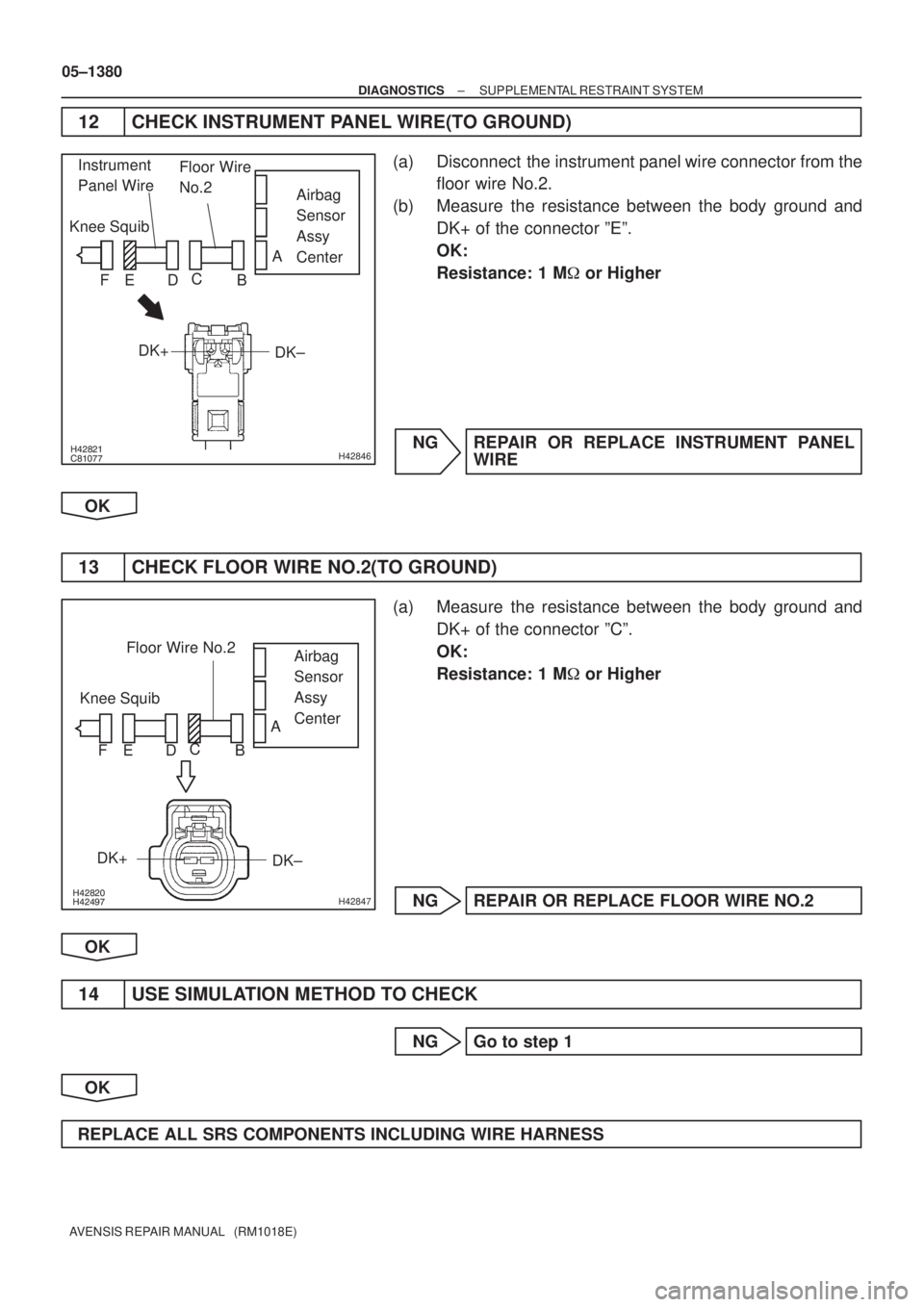
12 CHECK INSTRUMENT PANEL WIRE(TO GROUND)
(a) Disconnect the instrument panel wire connector from the
floor wire No.2.
(b) Measure the resistance between the body ground and
DK+ of the connector ºEº.
OK:
Resistance: 1 M� or Higher
NG REPAIR OR REPLACE INSTRUMENT PANEL
WIRE
OK
13 CHECK FLOOR WIRE NO.2(TO GROUND)
(a) Measure the resistance between the body ground and
DK+ of the connector ºCº.
OK:
Resistance: 1 M� or Higher
NG REPAIR OR REPLACE FLOOR WIRE NO.2
OK
14 USE SIMULATION METHOD TO CHECK
NG Go to step 1
OK
REPLACE ALL SRS COMPONENTS INCLUDING WIRE HARNESS
Page 1452 of 5135
�����������H42846
Airbag
Sensor
Assy
Center Knee Squib
DK± DK+Floor Wire
No.2 Instrument
Panel Wire
A
B C
D E F
����� �����H42847
Airbag
Sensor
Assy
Center Knee Squib
DK± DK+Floor Wire No.2
A
B C
D E F
± DIAGNOSTICSSUPPLEMENTAL RESTRAINT SYSTEM
05±1381
AVENSIS REPAIR MANUAL (RM1018E)
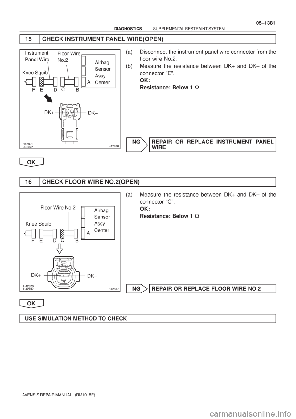
15 CHECK INSTRUMENT PANEL WIRE(OPEN)
(a) Disconnect the instrument panel wire connector from the
floor wire No.2.
(b) Measure the resistance between DK+ and DK± of the
connector ºEº.
OK:
Resistance: Below 1 �
NG REPAIR OR REPLACE INSTRUMENT PANEL
WIRE
OK
16 CHECK FLOOR WIRE NO.2(OPEN)
(a) Measure the resistance between DK+ and DK± of the
connector ºCº.
OK:
Resistance: Below 1 �
NG REPAIR OR REPLACE FLOOR WIRE NO.2
OK
USE SIMULATION METHOD TO CHECK
Page 1453 of 5135
�����\b�����H42846
Airbag
Sensor
Assy
Center
Knee Squib
DK±
DK+ Floor Wire
No.2
Instrument
Panel Wire
A
B
C
D
E
F
����� �����H42847
Airbag
Sensor
Assy
Center
Knee Squib
DK±
DK+ Floor Wire No.2
A
B
C
D
E
F
05±1382
±
DIAGNOSTICS SUPPLEMENTAL RESTRAINT SYSTEM
AVENSIS REPAIR MANUAL (RM1018E)
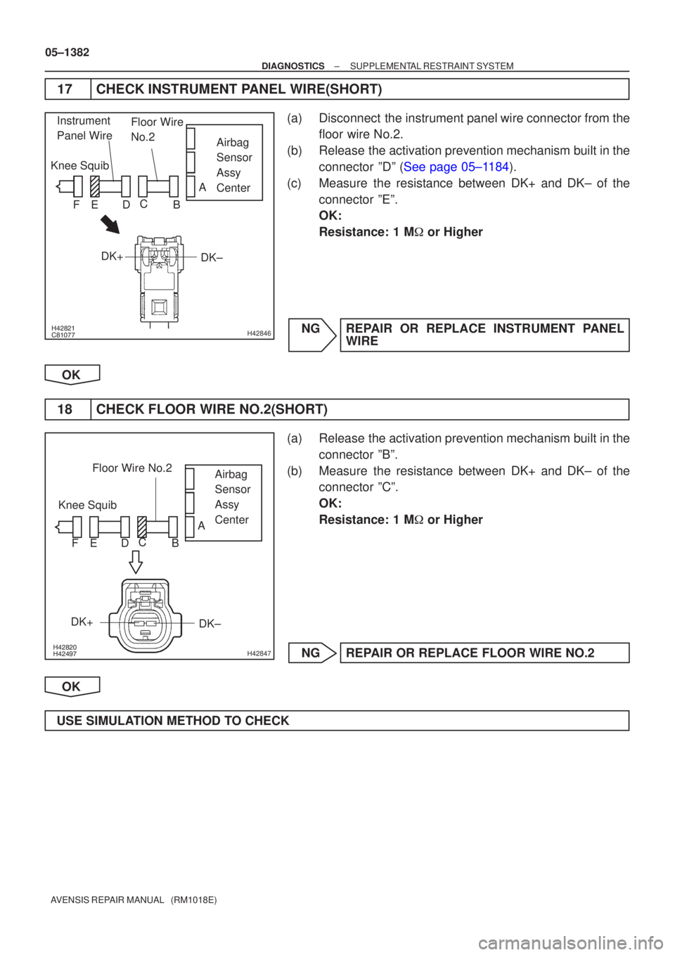
17CHECK INSTRUMENT PANEL WIRE(SHORT)
(a)Disconnect the instrument panel wire connector from the floor wire No.2.
(b)Release the activation prevention mechanism built in the connector ºDº (See page 05±1184).
(c) Measure the resistance between DK+ and DK± of the connector ºEº.
OK:
Resistance: 1 M � or Higher
NG REPAIR OR REPLACE INSTRUMENT PANEL WIRE
OK
18 CHECK FLOOR WIRE NO.2(SHORT)
(a) Release the activation prevention mechanism built in the connector ºBº.
(b) Measure the resistance between DK+ and DK± of the connector ºCº.
OK:
Resistance: 1 M � or Higher
NG REPAIR OR REPLACE FLOOR WIRE NO.2
OK
USE SIMULATION METHOD TO CHECK