Page 1414 of 5135

������
������ ������H40938
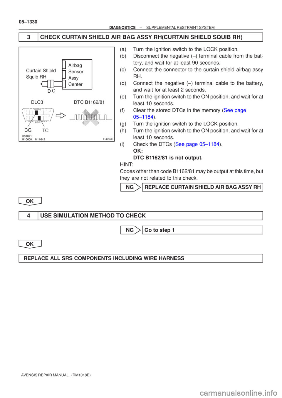
Airbag
Sensor
Assy
Center
Curtain Shield
Squib RH
DLC3
TC
CG
DTC B1162/81
C
D
05±1330
±
DIAGNOSTICS SUPPLEMENTAL RESTRAINT SYSTEM
AVENSIS REPAIR MANUAL (RM1018E)
3 CHECK CURTAIN SHIELD AIR BAG ASSY RH(CURTAIN SHIELD SQUIB RH)
(a) Turn the ignition switch to the LOCK position.
(b) Disconnect the negative (±) terminal cable from the bat- tery, and wait for at least 90 seconds.
(c) Connect the connector to the curtain shield airbag assy RH.
(d) Connect the negative (±) terminal cable to the battery, and wait for at least 2 seconds.
(e) Turn the ignition switch to the ON position, and wait for at least 10 seconds.
(f)Clear the stored DTCs in the memory (See page 05±1184).
(g) Turn the ignition switch to the LOCK position.
(h) Turn the ignition switch to the ON position, and wait for at least 10 seconds.
(i)Check the DTCs (See page 05±1184). OK:
DTC B1162/81 is not output.
HINT:
Codes other than code B1162/81 may be output at this time, but
they are not related to this check.
NG REPLACE CURTAIN SHIELD AIR BAG ASSY RH
OK
4 USE SIMULATION METHOD TO CHECK
NG Go to step 1
OK
REPLACE ALL SRS COMPONENTS INCLUDING WIRE HARNESS
Page 1425 of 5135

05±1404
± DIAGNOSTICSAUDIO SYSTEM
AVENSIS REPAIR MANUAL (RM1018E)
2. IDENTIFICATION OF NOISE SOURCE
(a) Identify the condition under which the noise occurs, and
check the noise filter on the related part.
Condition in which noise occursNoise Source
Depressing the acceleration pedal increases noise, and stopping the engine
erases the noise immediately.Generator
Noise occurs during the A/C or the heater operation.Blower motor
Rapid acceleration while driving on the unpaved road or after the IG switch is
turned ON makes noise.Fuel pump
Pressing and then releasing the horn switch, and keeping pressing the horn
switch makes unusual noise.Horn
Stopping the engine erases small noise that has been heard.Ignition
Noise occurs synchronously with the turn signal flash.Flasher
Noise occurs during the window washer operation.Washer
Noise occurs during the engine running, and it continues after the engine
stops.Engine coolant temperature sensor
Noise occurs during the wiper operation.Wiper
Noise occurs when the brake pedal is depressed.Stop light switch
Others.Static electricity stored on the vehicle
(b) Reference:
�Make sure first that there is no noise from outside.
Failing to do so makes the noise source detection
difficult and leads to misunderstanding.
�The noise should be removed in descending order
of loudness.
�Setting the radio untuned makes noise noticeable,
making the recognition of the phenomenon easier.
Page 1432 of 5135
H43588
Driver Side J/BAirbag Sensor Assy Center
D5 DLC3
TCW−
L
J21D
J/C
(*2) TC
(*2)
W− L
(*1) J20
B
(*2)
J8
B
(*1) W−
L
DB17
DD8
J8 B
(*1) A27
19
13 W−
L
1AZ−
FSE, 1CD− FTV Engine:
CG TC TC
TC
TC
W−
L
W− L
W− L
W−
L
W−B
W−
B
W−
B
W− B
(*1)
(*2) J9 J21
DD
(*2)(*1)
DL DC
15
3
E9
S1
S2
20
17
25
(*2)
A
J16
J/C
A
(*1)
IO IP
(*3)
M1
16
4
CA
CB 3
6
(*6)
(*4, *5)
Skid Control ECU with Actuator Skid Control ECU with Actuator ECM
Multi− Display
*1: LHD *2: RHD
*3: w/ Navigation System (Map Type) *4:
1AZ− FSE
*5: 1CD− FTV (w/ VSC)
*6: 1CD− FTV (w/ ABS)
Center J/B
−
DIAGNOSTICS SUPPLEMENTAL RESTRAINT SYSTEM
05−1391
TC TERMINAL CIRCUIT
CIRCUIT DESCRIPTION
DTC output mode is set by connecting terminals TC and CG of the DLC3.
The DTCs are displayed by blinking the SRS warning light.
WIRING DIAGRAM
05C65 −01
Page 1433 of 5135
H43587
Driver Side J/BAirbag Sensor Assy Center
D5 DLC3
TC W−
L
J8 TC
(*2)W−
L
(*1) W−
L
DB 17
DD8
B
(*1) A2719
*1: LHD W−
L
B
13
1AZ−
FE Engine:
W−L
W−
L
W−L
J8
J9 D
TCTC
TC
CG
W−
B
W− B
W− B W−
B
W−
L
M1 16
4
AJ16
J/C
A
IO IP
(*2)
(*1) (*3)
(*2)
(*3)
(*1) CA
CB 6
3 Center J/B J/C
DC
DL 3
15
E920
S2 25 ECM
Skid Control ECU with Actuator
Multi−
Display
*2: RHD
*3: w/ Navigation System (Map Type)
05−
1392
−
DIAGNOSTICS SUPPLEMENTAL RESTRAINT SYSTEM
Page 1434 of 5135
H43589
Driver Side J/BAirbag Sensor Assy Center
D5 DLC3
TCW−
L
J8 TC
(*2)
(*1)
W−L
DB 17
DD8
B
(*1) A27
19
*1: LHD B
13
1ZZ−
FE, 3ZZ −FE Engine:
W−L
W−
L
W−L
J8
J9 D
TCTC
TC
CG
W−
B
W− B
W−B W−
B
M116
4
AJ16
J/C
A
IO IP
(*2)
(*1) (*2)
(*1) CA
CB 6
3 J/C
DC
DL 3
15
E920
S2 25 ECM
Skid Control ECU with Actuator Multi−Display
*2: RHD
*3: w/ Navigation System (Map Type) B
B
J20 J20
(*1)
J9D
D
D
J21 J21
(*2)
TC
W−
L
W−
B(*1)
E15 4
W−L(*1) Center J/B
(*2) (*1)(*
1) (*2)
(*3)
W−
L
(*2) W−
L
(*2)
EPS ECU
−
DIAGNOSTICS SUPPLEMENTAL RESTRAINT SYSTEM
05−1392-1
HINT:
When each warning light stays blinking, a ground short in the wiring of terminal TC of the DLC3 or an internal
ground short in each ECU is suspected.
Page 1435 of 5135
H40065H40173H43360
DLC3:TC
Airbag Sensor Assy Center:
TC
A27
H40173CG
DLC3
05− 1392-2
−
DIAGNOSTICS SUPPLEMENTAL RESTRAINT SYSTEM
INSPECTION PROCEDURE
1 CHECK WIRE HARNESS(DLC3 −AIRBAG SENSOR ASSY CENTER)
(a) Turn the ignition switch to the LOCK position.
(b) Disconnect the airbag sensor assy center connector.
(c) Measure the resistance according to the value(s) in the
table below.
Standard:
Tester connectionConditionSpecified condition
DLC3 (TC) −A27−1 9 (TC)AlwaysBelow 1�
NG REPAIR OR REPLACE WIRE HARNESS(TC of
DLC3−TC of AIRBAG SENSOR ASSY CENTER)
OK
2 CHECK WIRE HARNESS(CG of DLC3 −BODY GROUND)
(a) Measure the resistance according to the value(s) in the
table below.
Standard:
Tester connectionConditionSpecified condition
DLC3 (CG) −
Body groundAlwaysBelow 1�
NG REPAIR OR REPLACE WIRE HARNESS(CG of
DLC3−BODY GROUND)
OK
Page 1436 of 5135
H40065
TC
A27
−
DIAGNOSTICS SUPPLEMENTAL RESTRAINT SYSTEM
05−1392-3
3 CHECK WIRE HARNESS(TC of AIRBAG SENSOR ASSY CENTER −BODY
GROUND)
(a) Measure the resistance according to the value(s) in the
table below.
Standard:
Tester connectionConditionSpecified condition
A27−1 9 (TC) −
Body groundAlways1 M� or Higher
NG REPAIR OR REPLACE WIRE HARNESS AND
EACH ECU
OK
REPLACE AIR BAG SENSOR ASSY CENTER
Page 1437 of 5135

± DIAGNOSTICSSUPPLEMENTAL RESTRAINT SYSTEM
05±1389
AVENSIS REPAIR MANUAL (RM1018E)
SRS WARNING LIGHT CIRCUIT MALFUNCTION (DOES NOT LIGHT
UP, WHEN IGNITION SWITCH IS TURNED TO ON)
CIRCUIT DESCRIPTION
The SRS warning light is located on the combination meter assy.
When the SRS is normal, the SRS warning light comes on for approx. 6 seconds after the ignition switch
is turned from the LOCK position to the ON position, and then it turns off automatically.
If there is a malfunction in the SRS, the SRS warning light comes on to inform a trouble to the driver.
When between terminal TC and terminal CG of the DLC3 are connected, the DTC is displayed by blinking
the SRS warning light.
WIRING DIAGRAM
See page .
INSPECTION PROCEDURE
1 CHECK SOURCE VOLTAGE
(a) Measure the voltage of the battery.
OK:
Voltage: 10 to 14 V
NG HARNESS BETWEEN BATTERY AND AIRBAG
SENSOR ASSY CENTER, AND CHARGING
SYSTEM
OK
2 CHECK AIR BAG SENSOR ASSY CENTER
(a) Turn the ignition switch to the LOCK position.
(b) Disconnect the negative (±) terminal cable from the battery, and wait for at least 90 seconds.
(c) Disconnect the connectors from the airbag sensor assy center.
(d) Connect the negative (±) terminal cable to the battery, and turn the ignition switch to the ON position.
(e) Check that the SRS warning light operation.
OK:
The SRS warning light does not come on.
NG REPLACE AIR BAG SENSOR ASSY CENTER
OK
056N4±03