Page 1438 of 5135
������
�����
C81395
05±1390
± DIAGNOSTICSSUPPLEMENTAL RESTRAINT SYSTEM
AVENSIS REPAIR MANUAL (RM1018E)
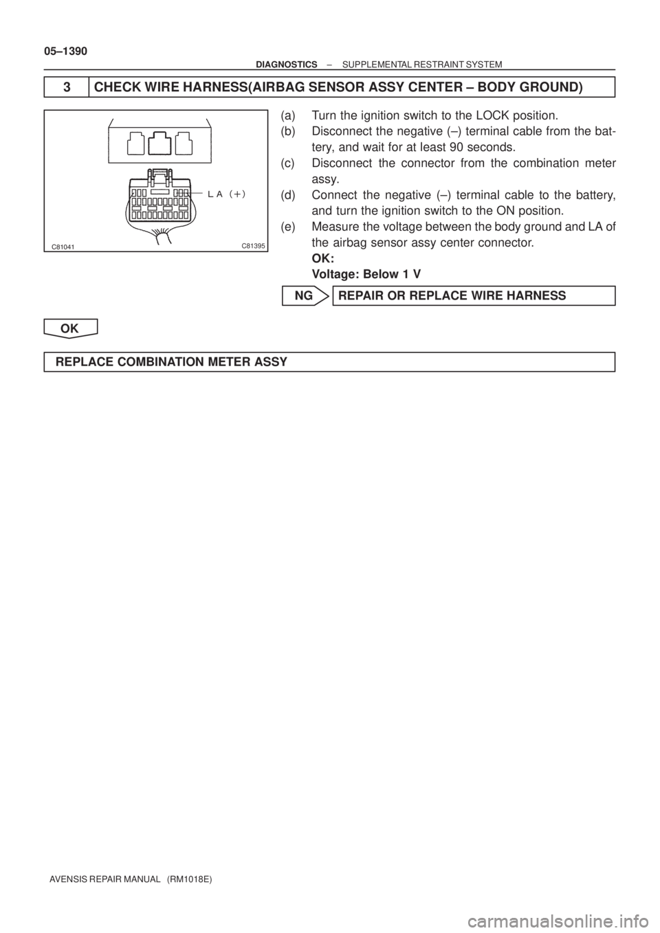
3 CHECK WIRE HARNESS(AIRBAG SENSOR ASSY CENTER ± BODY GROUND)
(a) Turn the ignition switch to the LOCK position.
(b) Disconnect the negative (±) terminal cable from the bat-
tery, and wait for at least 90 seconds.
(c) Disconnect the connector from the combination meter
assy.
(d) Connect the negative (±) terminal cable to the battery,
and turn the ignition switch to the ON position.
(e) Measure the voltage between the body ground and LA of
the airbag sensor assy center connector.
OK:
Voltage: Below 1 V
NG REPAIR OR REPLACE WIRE HARNESS
OK
REPLACE COMBINATION METER ASSY
Page 1439 of 5135
H42518
Combination Meter Assy
Driver Side J/BAirbag Sensor Assy Center
*1: LHD
*2: RHD
*3: Gasoline
*4: 1CD±FTV SRS8
C11B±Y
J16
J/C(*2)
IL 17
C1012
DA6
DDB±Y3
A27
LA
W±B
J15
J/C W±B
(*1)
A
AW±B
W±B
(*1, *4)(*1, *3)(*2) W±B
A
A J17
J/C
A
IO
IK 05±1386
± DIAGNOSTICSSUPPLEMENTAL RESTRAINT SYSTEM
AVENSIS REPAIR MANUAL (RM1018E)
SRS WARNING LIGHT CIRCUIT MALFUNCTION (ALWAYS LIGHT
UP, WHEN IGNITION SWITCH IS ACC OR LOCK POSITION)
CIRCUIT DESCRIPTION
The SRS warning light is located on the combination meter assy.
When the SRS is normal, the SRS warning light comes on for approx. 6 seconds after the ignition switch
is turned from the LOCK position to the ON position, and then it turns off automatically.
If there is a malfunction in the SRS, the SRS warning light comes on to inform a trouble to the driver.
When between terminal TC and terminal CG of the DLC3 are connected, the DTC is displayed by blinking
the SRS warning light.
WIRING DIAGRAM
05C64±01
Page 1440 of 5135

INSPECTION PROCEDURE
1 CHECK CONNECTOR
(a) Turn the ignition switch to the LOCK")
H42822
C11±8
������
�����
C81395
± DIAGNOSTICSSUPPLEMENTAL RESTRAINT SYSTEM
05±1387
AVENSIS REPAIR MANUAL (RM1018E)
INSPECTION PROCEDURE
1 CHECK CONNECTOR
(a) Turn the ignition switch to the LOCK position.
(b) Disconnect the negative (±) terminal cable from the battery, and wait for at least 90 seconds.
(c) Check that the connection of the airbag sensor assy center connectors.
OK:
The connectors are connector.
NG CONNECT CONNECTORS
OK
2 CHECK WIRE HARNESS(COMBINATION METER ASSY ± BODY GROUND)
(a) Disconnect the connector from the combination meter
assy.
(b) Connect the negative (±) terminal cable to the battery,
and turn the ignition switch to the ON position.
(c) Measure the voltage between the body ground and termi-
nal C11±8 of the combination meter assy.
OK:
Voltage: Below 8 V
NG REPAIR OR REPLACE COMBINATION METER
ASSY
OK
3 CHECK WIRE HARNESS(AIRBAG SENSOR ASSY CENTER ± COMBINATION
METER ASSY)
(a) Disconnect the negative (±) terminal cable from the bat-
tery, and wait for at least 90 seconds.
(b) Disconnect the connector from the airbag sensor assy
center.
(c) Measure the resistance between the body ground and
terminal LA of the connector on the airbag sensor assy
center side.
OK:
Resistance : 1 M� or Higher
NG REPAIR OR REPLACE WIRE HARNESS
(AIRBAG SENSOR ASSY CENTER ±
COMBINATION METER ASSY)
OK
Page 1441 of 5135
��
������H42848
Airbag Sensor Assy Center
Combination Meter Assy
C11±8
05±1388
± DIAGNOSTICSSUPPLEMENTAL RESTRAINT SYSTEM
AVENSIS REPAIR MANUAL (RM1018E)
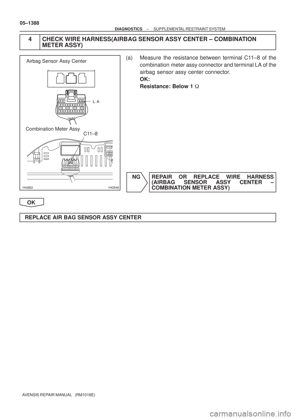
4 CHECK WIRE HARNESS(AIRBAG SENSOR ASSY CENTER ± COMBINATION
METER ASSY)
(a) Measure the resistance between terminal C11±8 of the
combination meter assy connector and terminal LA of the
airbag sensor assy center connector.
OK:
Resistance: Below 1 �
NG REPAIR OR REPLACE WIRE HARNESS
(AIRBAG SENSOR ASSY CENTER ±
COMBINATION METER ASSY)
OK
REPLACE AIR BAG SENSOR ASSY CENTER
Page 1442 of 5135

H42517
Airbag Sensor Assy Center
A275
E1
E2 27IG2 2
1
Battery28 4IGN Driver Side J/B
IG2
AM2 I13
Ignition SW
B
4 3 6
Engine Room R/B No.1, Engine Room J/B No.1 AM2B±R
DD
W±BB±W
A27
A27 DD DH5
DAW±B 1 11
B±R1
1
1A
2
1 IE4 IP1
(*3)
(*4)(*1) B±G
Engine Room R/B No.3
Engine Room J/B No.43
DD 4B4A
3 9(*1) B±G (*2)
(*1) B±GB
(*2)
Driver Side J/B
IJ FL MAIN
W±B
*1: Gasoline
*2: 1CD±FTV*3: LHD
*4: RHD B±R
± DIAGNOSTICSSUPPLEMENTAL RESTRAINT SYSTEM
05±1383
AVENSIS REPAIR MANUAL (RM1018E)
SOURCE VOLTAGE DROP
CIRCUIT DESCRIPTION
The SRS is equipped with a voltage±increase circuit (DC±DC converter) in the airbag sensor assy center
in case the source voltage drops.
When the battery voltage drops, the voltage±increase circuit (DC±DC converter) functions to increase the
voltage of the SRS to normal voltage.
A malfunction in this circuit is displayed by different form from the other code. The source voltage drop is
indicated when the SRS warning light comes on without showing any DTCs.
Malfunction in this circuit is not recorded in the airbag sensor assy center. The SRS warning light automatical-
ly goes off when the source voltage returns to normal.
DTC No.Diagnosis
(Normal)Source voltage drop
WIRING DIAGRAM
056N1±04
Page 1443 of 5135

INSPECTION PROCEDURE
1PREPARE FOR INSPECTION
(a)Turn the ignition switch to the LOCK position.")
H40065
IG2
E2 E1
05±1384
±
DIAGNOSTICS SUPPLEMENTAL RESTRAINT SYSTEM
AVENSIS REPAIR MANUAL (RM1018E)
INSPECTION PROCEDURE
1PREPARE FOR INSPECTION
(a)Turn the ignition switch to the LOCK position.
(b)Disconnect the negative (±) terminal cable from the battery, and wait for at least 90 seconds.
(c)Disconnect the connectors of the airbag sensor assy center (See page 60±62).
2 CHECK SOURCE VOLTAGE
(a) Connect the negative (±) terminal cable to the battery, and turn the ignition switch to the ON position.
(b) Measure the voltage between E1 (E2) and IG2 on the air- bag sensor assy center side and operate electric system
(defogger, wiper, headlight, heater blower, etc.).
OK:
Voltage: 10 to 14 V
NG REPAIR OR REPLACE HARNESS BETWEEN BATTERY AND AIRBAG SENSOR ASSY
CENTER, AND CHARGING SYSTEM
OK
3 CHECK SRS WARNING LIGHT TURN OFF
(a) Turn the ignition switch to the LOCK position.
(b) Disconnect the negative (±) terminal cable from the battery, and wait for at least 90 seconds.
(c) Connect the airbag sensor assy center connectors.
(d) Connect the negative (±) terminal cable to the battery, and wait for at least 2 seconds.
(e) Turn the ignition switch to the ON position, and wait for at least 10 sec\
onds.
(f) Operate electric system (defogger, wiper, headlight, heater blower, etc.) and check that SRS warning light goes off.
OK:
SRS warning light does not come on.
NG REPAIR OR REPLACE HARNESS BETWEENBATTERY AND AIRBAG SENSOR ASSY
CENTER, AND CHARGING SYSTEM
OK
Page 1444 of 5135
±
DIAGNOSTICS SUPPLEMENTAL RESTRAINT SYSTEM
05±1385
AVENSIS REPAIR MANUAL (RM1018E)
4CHECK AIR BAG SENSOR ASSY CENTER
(a)Turn the ignition switch to the LOCK position.
(b)Disconnect the negative (±) terminal cable from the battery, and wait for at least 90 seconds.
(c)Connect the negative (±) terminal cable to the battery, and wait for at least 2 seconds.
(d)Turn the ignition switch to the ON position, and wait for at least 10 sec\
onds.
(e)Clear the stored DTCs in the memory (See page 05±1184).
(f)Turn the ignition switch to the LOCK position.
(g)Turn the ignition switch to the ON position, and wait for at least 10 sec\
onds.
(h)Check the DTCs (See page 05±1184).
OK:
DTC is not output.
NG REPLACE AIR BAG SENSOR ASSY CENTER
OK
USE SIMULATION METHOD TO CHECK
Page 1445 of 5135

DTC B")
H42516
K3
Knee Airbag SquibAirbag Sensor Assy Center
Y±R
IN1
2
1A2811
DK±
1 2
A2812
IN1 Y±BY±R
Y±B
DK+ 05±1374
± DIAGNOSTICSSUPPLEMENTAL RESTRAINT SYSTEM
AVENSIS REPAIR MANUAL (RM1018E)
DTC B1650/49 SHORT IN KNEE SQUIB CIRCUIT
DTC B1651/49 OPEN IN KNEE SQUIB CIRCUIT
DTC B1652/49 SHORT IN KNEE SQUIB CIRCUIT (TO
GROUND)
DTC B1653/49 SHORT IN KNEE SQUIB CIRCUIT (TO B+)
CIRCUIT DESCRIPTION
The knee squib circuit consists of the airbag sensor assy center and the instrument panel airbag assy.
This circuit actuates the SRS to deploy when the SRS deployment conditions are fulfilled.
When the malfunction is detected in the knee squib circuit under the following conditions, these codes are
recorded.
�DTC B1650/49 is for short circuit
�DTC B1651/49 is for open circuit
�DTC B1652/49 is for short to ground
�DTC B1653/49 is for short to B+
DTC No.DTC Detection ConditionTrouble Area
B1650/49
B1651/49
B1652/49
B1653/49
�Short circuit between DK+ wire harness and DK± wire har-
ness of squib
�Open circuit in DK+ wire harness or DK± wire harness of
squib
�Short circuit in knee squib wire harness (to ground)
�Short circuit in knee squib wire harness (to B+)
�Knee squib malfunction
�Airbag sensor assy center
�Instrument panel airbag assy (Knee squib)
�Instrument panel wire
�Floor wire No.2
�Airbag sensor assy center
WIRING DIAGRAM
05C63±01

IL 17
C1012
DA6
DDB±Y3
A27
LA
W±B
J15
J/C W±B
(*1)
A
AW±B")

4CHECK AIR BAG SENSOR ASSY CENTER
(a)Turn the ignition switch to the LOCK position.
(b)Disconnect the negative (")