Page 5 of 5135
022J5±01
± PREPARATIONENGINE CONTROL SYSTEM
02±3
AVENSIS REPAIR MANUAL (RM1018E)
ENGINE CONTROL SYSTEM
PREPARATION
SST
09268±21010Fuel Hose PullerKNOCK SENSOR(1AZ±FE)
Recomended Tools
09082±00040TOYOTA Electrical TesterSFI SYSTEM(1AZ±FE)
SFI SYSTEM(1AZ±FSE)
SFI SYSTEM(1ZZ±FE/3ZZ±FE)
(09083±00150)Test Lead SetSFI SYSTEM(1AZ±FE)
SFI SYSTEM(1AZ±FSE)
SFI SYSTEM(1ZZ±FE/3ZZ±FE)
Equipment
Ohmmeter
Radiator cap tester
Service Wire Harness
Torque wrench
Vernier calipers
Voltmeter
Page 9 of 5135
± INTRODUCTIONTERMS
01±43
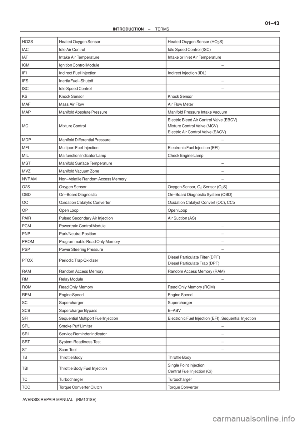
AVENSIS REPAIR MANUAL (RM1018E) HO2S
Heated Oxygen SensorHeated Oxygen Sensor (HO2S)
IACIdle Air ControlIdle Speed Control (ISC)
IATIntake Air TemperatureIntake or Inlet Air Temperature
ICMIgnition Control Module±
IFIIndirect Fuel InjectionIndirect Injection (IDL)
IFSInertia Fuel±Shutoff±
ISCIdle Speed Control±
KSKnock SensorKnock Sensor
MAFMass Air FlowAir Flow Meter
MAPManifold Absolute PressureManifold Pressure Intake Vacuum
MCMixture Control
Electric Bleed Air Control Valve (EBCV)
Mixture Control Valve (MCV)
Electric Air Control Valve (EACV)
MDPManifold Differential Pressure±
MFIMultiport Fuel InjectionElectronic Fuel Injection (EFI)
MILMalfunction Indicator LampCheck Engine Lamp
MSTManifold Surface Temperature±
MVZManifold Vacuum Zone±
NVRAMNon±Volatile Random Access Memory±
O2SOxygen SensorOxygen Sensor, O2 Sensor (O2S)
OBDOn±Board DiagnosticOn±Board Diagnostic System (OBD)
OCOxidation Catalytic ConverterOxidation Catalyst Convert (OC), CCo
OPOpen LoopOpen Loop
PAIRPulsed Secondary Air InjectionAir Suction (AS)
PCMPowertrain Control Module±
PNPPark/Neutral Position±
PROMProgrammable Read Only Memory±
PSPPower Steering Pressure±
PTOXPeriodic Trap OxidizerDiesel Particulate Filter (DPF)
Diesel Particulate Trap (DPT)
RAMRandom Access MemoryRandom Access Memory (RAM)
RMRelay Module±
ROMRead Only MemoryRead Only Memory (ROM)
RPMEngine SpeedEngine Speed
SCSuperchargerSupercharger
SCBSupercharger BypassE±ABV
SFISequential Multiport Fuel InjectionElectronic Fuel Injection (EFI), Sequential Injection
SPLSmoke Puff Limiter±
SRIService Reminder Indicator±
SRTSystem Readiness Test±
STScan Tool±
TBThrottle BodyThrottle Body
TBIThrottle Body Fuel InjectionSingle Point Injection
Central Fuel Injection (Ci)
TCTurbochargerTurbocharger
TCCTorque Converter ClutchTorque Converter
Page 10 of 5135
01±44
± INTRODUCTIONTERMS
AVENSIS REPAIR MANUAL (RM1018E) TCM
Transmission Control ModuleTransmission ECU, ECT ECU
TPThrottle PositionThrottle Position
TRTransmission Range±
TVVThermal Vacuum ValveBimetallic Vacuum Switching Valve (BVSV)
Thermostatic Vacuum Switching Valve (TVSV)
TWCThree±Way Catalytic Converter
Three±Way Catalytic (TWC)
Manifold Converter
CC
RO
TWC+OCThree±Way + Oxidation Catalytic ConverterCCR + CCo
VA FVolume Air FlowAir Flow Meter
VRVoltage RegulatorVoltage Regulator
VSSVehicle Speed SensorVehicle Speed Sensor
WOTWide Open ThrottleFull Throttle
WU±OCWarm Up Oxidation Catalytic Converter±
WU±TWCWarm Up Three±Way Catalytic Converter±
3GRThird Gear±
4GRFourth Gear±
Page 11 of 5135
010B9±11
± INTRODUCTIONTERMS
01±37
AVENSIS REPAIR MANUAL (RM1018E)
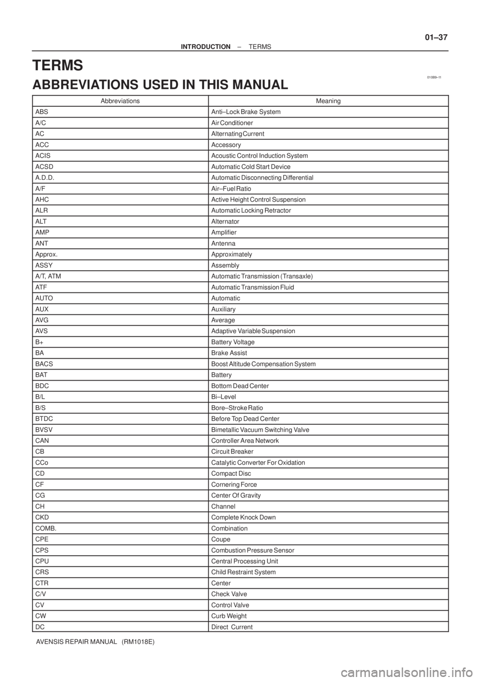
TERMS
ABBREVIATIONS USED IN THIS MANUAL
AbbreviationsMeaning
ABSAnti±Lock Brake System
A/CAir Conditioner
ACAlternating Current
ACCAccessory
ACISAcoustic Control Induction System
ACSDAutomatic Cold Start Device
A.D.D.Automatic Disconnecting Differential
A/FAir±Fuel Ratio
AHCActive Height Control Suspension
ALRAutomatic Locking Retractor
ALTAlternator
AMPAmplifier
ANTAntenna
Approx.Approximately
ASSYAssembly
A/T, ATMAutomatic Transmission (Transaxle)
AT FAutomatic Transmission Fluid
AUTOAutomatic
AUXAuxiliary
AV GAverage
AV SAdaptive Variable Suspension
B+Battery Voltage
BABrake Assist
BACSBoost Altitude Compensation System
BATBattery
BDCBottom Dead Center
B/LBi±Level
B/SBore±Stroke Ratio
BTDCBefore Top Dead Center
BVSVBimetallic Vacuum Switching Valve
CANController Area Network
CBCircuit Breaker
CCoCatalytic Converter For Oxidation
CDCompact Disc
CFCornering Force
CGCenter Of Gravity
CHChannel
CKDComplete Knock Down
COMB.Combination
CPECoupe
CPSCombustion Pressure Sensor
CPUCentral Processing Unit
CRSChild Restraint System
CTRCenter
C/VCheck Valve
CVControl Valve
CWCurb Weight
DCDirect Current
Page 13 of 5135
± INTRODUCTIONTERMS
01±39
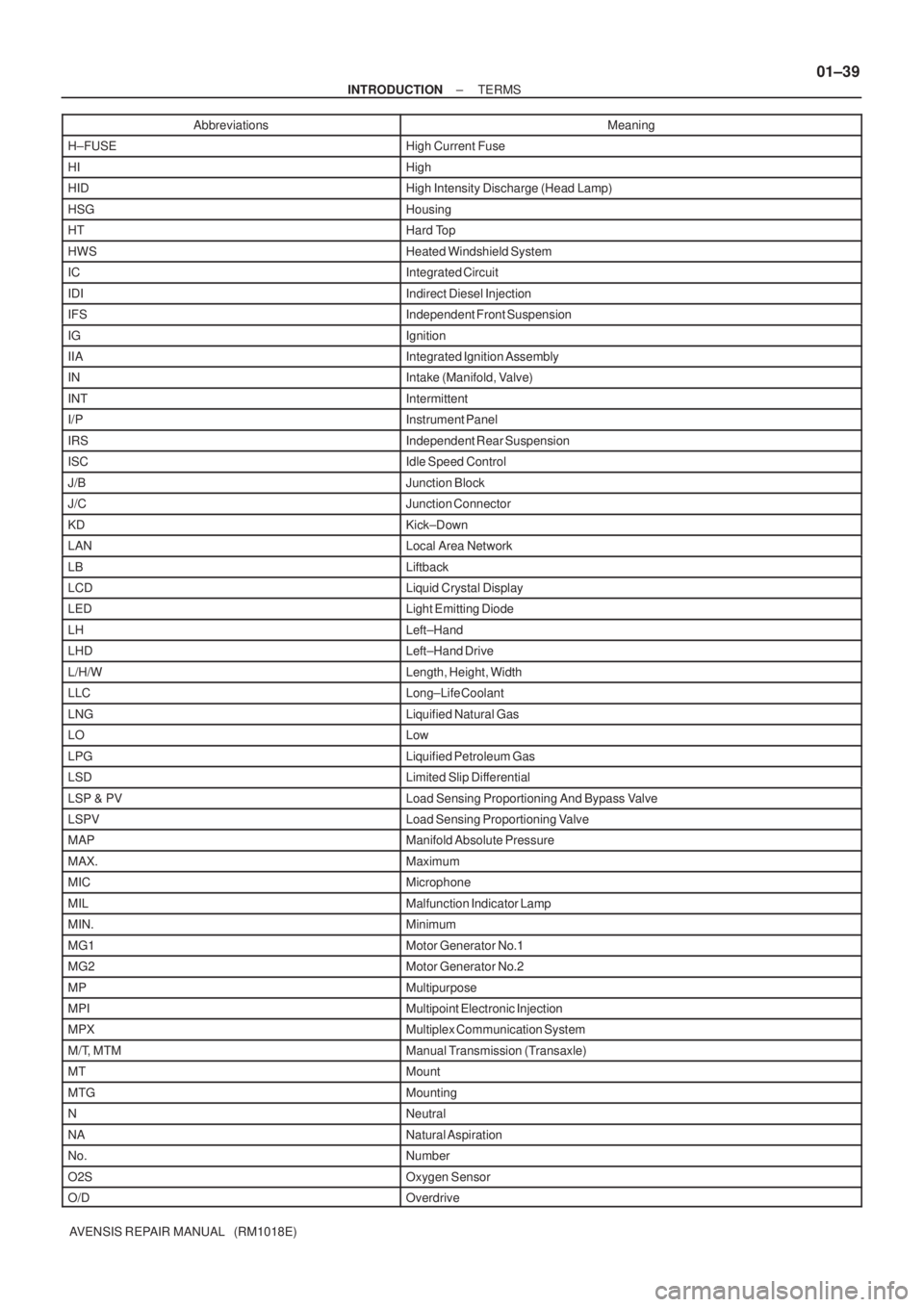
AVENSIS REPAIR MANUAL (RM1018E)Abbreviations Meaning
H±FUSEHigh Current Fuse
HIHigh
HIDHigh Intensity Discharge (Head Lamp)
HSGHousing
HTHard Top
HWSHeated Windshield System
ICIntegrated Circuit
IDIIndirect Diesel Injection
IFSIndependent Front Suspension
IGIgnition
IIAIntegrated Ignition Assembly
INIntake (Manifold, Valve)
INTIntermittent
I/PInstrument Panel
IRSIndependent Rear Suspension
ISCIdle Speed Control
J/BJunction Block
J/CJunction Connector
KDKick±Down
LANLocal Area Network
LBLiftback
LCDLiquid Crystal Display
LEDLight Emitting Diode
LHLeft±Hand
LHDLeft±Hand Drive
L/H/WLength, Height, Width
LLCLong±Life Coolant
LNGLiquified Natural Gas
LOLow
LPGLiquified Petroleum Gas
LSDLimited Slip Differential
LSP & PVLoad Sensing Proportioning And Bypass Valve
LSPVLoad Sensing Proportioning Valve
MAPManifold Absolute Pressure
MAX.Maximum
MICMicrophone
MILMalfunction Indicator Lamp
MIN.Minimum
MG1Motor Generator No.1
MG2Motor Generator No.2
MPMultipurpose
MPIMultipoint Electronic Injection
MPXMultiplex Communication System
M/T, MTMManual Transmission (Transaxle)
MTMount
MTGMounting
NNeutral
NANatural Aspiration
No.Number
O2SOxygen Sensor
O/DOverdrive
Page 14 of 5135
01±40
± INTRODUCTIONTERMS
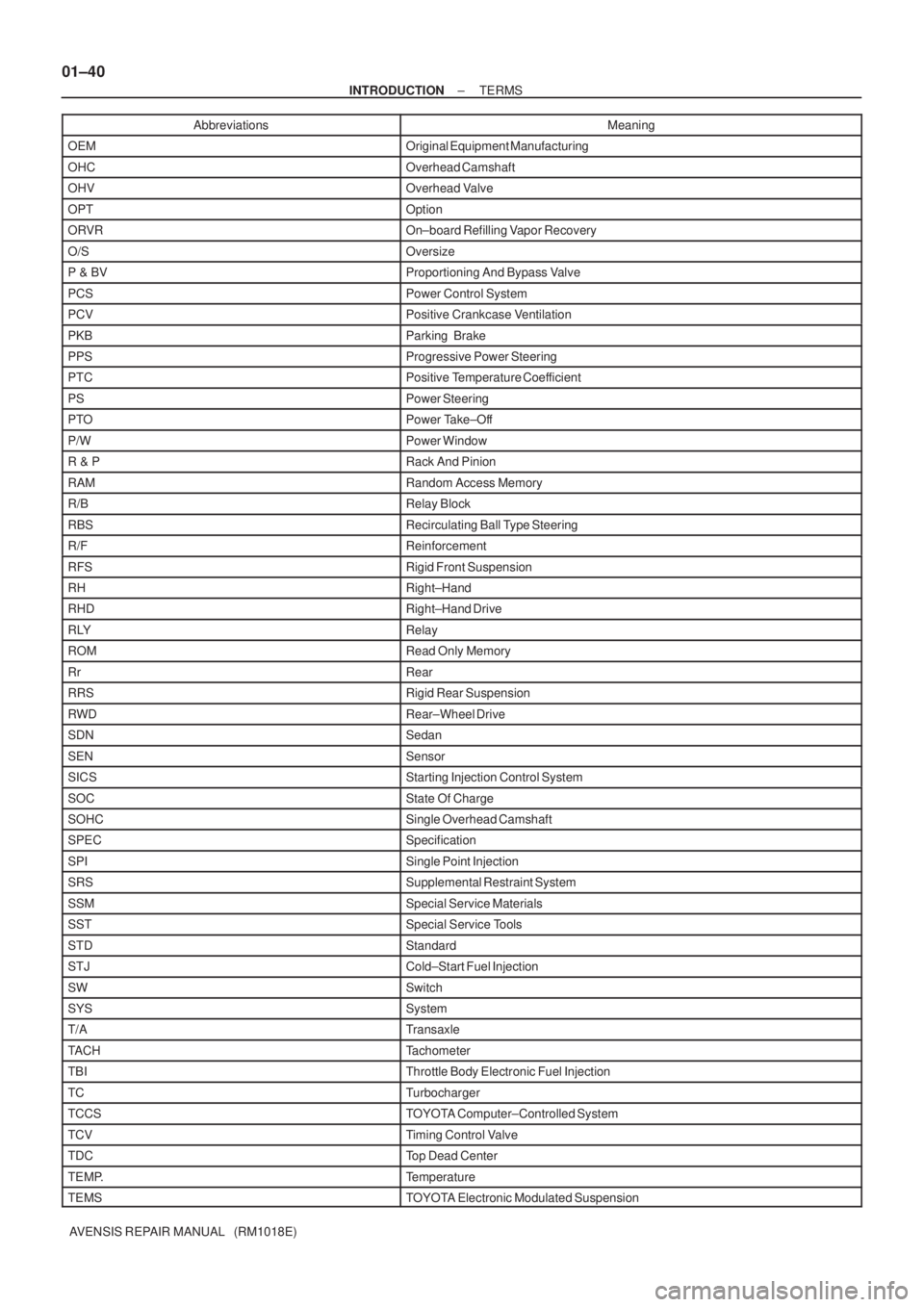
AVENSIS REPAIR MANUAL (RM1018E)Abbreviations Meaning
OEMOriginal Equipment Manufacturing
OHCOverhead Camshaft
OHVOverhead Valve
OPTOption
ORVROn±board Refilling Vapor Recovery
O/SOversize
P & BVProportioning And Bypass Valve
PCSPower Control System
PCVPositive Crankcase Ventilation
PKBParking Brake
PPSProgressive Power Steering
PTCPositive Temperature Coefficient
PSPower Steering
PTOPower Take±Off
P/WPower Window
R & PRack And Pinion
RAMRandom Access Memory
R/BRelay Block
RBSRecirculating Ball Type Steering
R/FReinforcement
RFSRigid Front Suspension
RHRight±Hand
RHDRight±Hand Drive
RLYRelay
ROMRead Only Memory
RrRear
RRSRigid Rear Suspension
RWDRear±Wheel Drive
SDNSedan
SENSensor
SICSStarting Injection Control System
SOCState Of Charge
SOHCSingle Overhead Camshaft
SPECSpecification
SPISingle Point Injection
SRSSupplemental Restraint System
SSMSpecial Service Materials
SSTSpecial Service Tools
STDStandard
STJCold±Start Fuel Injection
SWSwitch
SYSSystem
T/ATransaxle
TACHTachometer
TBIThrottle Body Electronic Fuel Injection
TCTurbocharger
TCCSTOYOTA Computer±Controlled System
TCVTiming Control Valve
TDCTop Dead Center
TEMP.Temperature
TEMSTOYOTA Electronic Modulated Suspension
Page 17 of 5135

D25088
Same terminal as
a male terminal
D20024
WRONG
CORRECT
D01557
WRONG
Z17004
C
SensorOPEN
1
2B
1
21
21
2A
Fig. 1
ECU
± INTRODUCTIONHOW TO TROUBLESHOOT ECU CONTROLLED
SYSTEMS01±33
AVENSIS REPAIR MANUAL (RM1018E)
(3) Checking of the contact pressure of the terminal:
Prepare a spare male terminal.
Insert it into a female terminal, check the engaged
condition and sliding resistance.
(d) REPAIR METHOD OF CONNECTOR TERMINAL
(1) If there is on the contact point, clean the contact
point using an air gun or shop rag. However, never
polish the contact point using sand paper as the
platings may come off.
(2) In case of abnormal contact pressure, replace the
female terminal. However, if a male terminal is gold±
plated (gold color), use gold±plated female terminal
and if it is silver±plated (silver color), use silver±
plated female terminal.
(e) HANDLING OF WIRE HARNESS
(1) When removing the wire harness, check the posi-
tioning of the wiring and clamping before starting
work in order to be able to restore it correctly.
(2) Never twist, pull or loosen the wire harness more
than necessary.
(3) Never allow the wire harness to come into contact
with a high±temperature, rotating, moving, vibrating
or sharp (edge of the panel, tip of the screw, etc.)
part.
(4) When installing parts, never let the wire harness be
interfered with.
(5) Never cut or break the cover of the wire harness. If
one is cut or broken, replace it or securely repair it
with electrical tape.
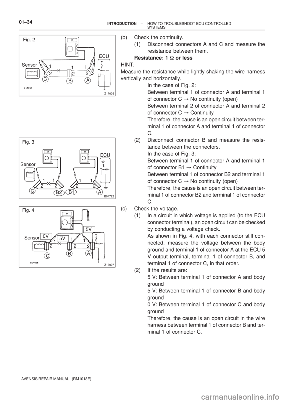
2. CHECK OPEN CIRCUIT
(a) For the open circuit in the wire harness in Fig. 1, perform
a continuity check in step (b) or a voltage check in step (c)
to locate the section.
Page 18 of 5135
Z17005
Fig. 2
Sensor
C
BA
ECU
1
21
22 1
B04722
Fig. 3
Sensor
B2
A
1
21
2
21
C
B1
1
2ECU
Z17007
Fig. 4
Sensor
CBA
1
21
2
2 15V
5V
0V 01±34
± INTRODUCTIONHOW TO TROUBLESHOOT ECU CONTROLLED
SYSTEMS
AVENSIS REPAIR MANUAL (RM1018E)
(b) Check the continuity.
(1) Disconnect connectors A and C and measure the
resistance between them.
Resistance: 1 � or less
HINT:
Measure the resistance while lightly shaking the wire harness
vertically and horizontally.
In the case of Fig. 2:
Between terminal 1 of connector A and terminal 1
of connector C � No continuity (open)
Between terminal 2 of connector A and terminal 2
of connector C � Continuity
Therefore, the cause is an open circuit between ter-
minal 1 of connector A and terminal 1 of connector
C.
(2) Disconnect connector B and measure the resis-
tance between the connectors.
In the case of Fig. 3:
Between terminal 1 of connector A and terminal 1
of connector B1 � Continuity
Between terminal 1 of connector B2 and terminal 1
of connector C � No continuity (open)
Therefore, the cause is an open circuit between ter-
minal 1 of connector B2 and terminal 1 of connector
C.
(c) Check the voltage.
(1) In a circuit in which voltage is applied (to the ECU
connector terminal), an open circuit can be checked
by conducting a voltage check.
As shown in Fig. 4, with each connector still con-
nected, measure the voltage between the body
ground and terminal 1 of connector A at the ECU 5
V output terminal, terminal 1 of connector B, and
terminal 1 of connector C, in that order.
(2) If the results are:
5 V: Between terminal 1 of connector A and body
ground
5 V: Between terminal 1 of connector B and body
ground
0 V: Between terminal 1 of connector C and body
ground
Therefore, the cause is an open circuit in the wire
harness between terminal 1 of connector B and ter-
minal 1 of connector C.