Page 1728 of 5135

T13
Rear Theft Warning
Radar")
B67699
S+B
IOUT 24
26 L±W
L±B 9 T12
Theft Warning Radar Sensor
6 S+B
IOUT
SOFF7
W±BSSW1
13 LG±B
ID18T6
Theft Warning ECU Assy
T14
Rear Theft Warning
Radar Sensor (IN)
T13
Rear Theft Warning
Radar Sensor (OUT)
IJ DA DK9 6 LG±B L±B L±W
ID1 ID1
W±B 19
SOU+
SOU±GND SIN+
SIN± 2
1
2
18
4
1 53 W
P
L
2 MIN+
MIN±
MOU+
MOU±Instrument Panel J/B Assy Shielded 05±1650
± DIAGNOSTICSTHEFT DETERRENT SYSTEM
AVENSIS REPAIR MANUAL (RM1018E)
INTRUSION SENSOR CIRCUIT
CIRCUIT DESCRIPTION
The intrusion sensor (theft warning radar sensor) senses any moving object by using ultrasonic waves and
outputs the signals to inform the theft warning ECU of an intrusion, so that the theft deterrent system can
set off the alarm.
When the theft deterrent system is switched to the arming preparation state, the intrusion sensor is supplied
with S+B by the theft warning ECU. This causes the theft deterrent system to set off the alarm when the signal
is input from the intrusion sensor in a situation such as when the window glass is broken.
WIRING DIAGRAM
05BAH±01
Page 1729 of 5135

LOW
(0.2 ± 0.8 V)T1: 0.2 sec.
T2: 0.1 sec.
T1T2
± DIAGNOSTICSTHEFT DETERRENT SYSTEM
05±1651
AVENSIS REPAIR MANUAL (RM101")
B67866
T12
Theft Warning Radar Sensor
1 2 4
87653
B69135
HIGH
(10 ± 14 V)
LOW
(0.2 ± 0.8 V)T1: 0.2 sec.
T2: 0.1 sec.
T1T2
± DIAGNOSTICSTHEFT DETERRENT SYSTEM
05±1651
AVENSIS REPAIR MANUAL (RM1018E)
INSPECTION PROCEDURE
1 CHECK THEFT WARNING RADAR SENSOR (OPERATION)
(a) Set the theft deterrent system with a window open and after 30 seconds insert your hand through the
window and shake it near the sensor to check if the alarm is triggered.
OK NO PROBLEM
NG
2 CHECK THEFT WARNING RADAR SENSOR (VOLTAGE, RESISTANCE)
(a) Check the voltage or resistance between each terminal of
the connector and the body ground.
Tester ConnectionConditionSpecified Condition
T12±7 (S+B) ±
Body ground
Arming preparation state
or armed state10 to 14 V
Body groundDisarmed stateBelow 1 V
When sensor does not de-
tect any movement10 to 14 V
T12±6 (IOUT) ±
Body groundWhen sensor detects
movement when in arming
preparation state or armed
state
Using an oscilloscope *2
T12±3 (SOFF) ± OFF Switch ONBelow 1 �T12 3 (SOFF)
Body ground
OFF Switch OFF10 k� or higher
T12±2 (GND) ±
Body groundConstantBelow 1 �
*1
T12±8 (SIN+) ±
T12±4 (SIN±)Disarmed state5 ± 10 k�
*1
T12±1 (SOU+) ±
T12±5 (SOU±)Disarmed state1 M� or higher
HINT:
*
1: Wagon only
Wave pattern (*
2):
NG REPLACE THEFT WARNING RADAR SENSOR
OK
Page 1730 of 5135
B67867
1 2
������
������B68491
Wire Harness Side
T6
Theft Warning ECU Assy
T12
Theft Warning Radar Sensor
05±1652
± DIAGNOSTICSTHEFT DETERRENT SYSTEM
AVENSIS REPAIR MANUAL (RM1018E)
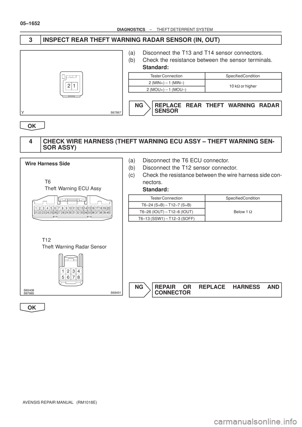
3 INSPECT REAR THEFT WARNING RADAR SENSOR (IN, OUT)
(a) Disconnect the T13 and T14 sensor connectors.
(b) Check the resistance between the sensor terminals.
Standard:
Tester ConnectionSpecified Condition
2 (MIN+) ± 1 (MIN±)10 k�or higher2 (MOU+) ± 1 (MOU±)10 k� or higher
NG REPLACE REAR THEFT WARNING RADAR
SENSOR
OK
4 CHECK WIRE HARNESS (THEFT WARNING ECU ASSY ± THEFT WARNING SEN-
SOR ASSY)
(a) Disconnect the T6 ECU connector.
(b) Disconnect the T12 sensor connector.
(c) Check the resistance between the wire harness side con-
nectors.
Standard:
Tester ConnectionSpecified Condition
T6±24 (S+B) ± T12±7 (S+B)
T6±26 (IOUT) ± T12±6 (IOUT)Below 1 �
T6±13 (SSW1) ± T12±3 (SOFF)
NG REPAIR OR REPLACE HARNESS AND
CONNECTOR
OK
Page 1731 of 5135

������
������B68492
Wire Harness Side
T12
Theft Warning Radar Sensor
T13
T14
Rear Theft Warning Radar Sensor
B67865
Wire Harness Side
T12
Theft Warning Radar Sensor
± DIAGNOSTICSTHEFT DETERRENT SYSTEM
05±1653
AVENSIS REPAIR MANUAL (RM1018E)
5 CHECK WIRE HARNESS (THEFT WARNING SENSOR ASSY ± REAR THEFT
WARNING SENSOR ASSY (IN, OUT))
(a) Disconnect the T12, T13 and T14 sensor connectors.
(b) Check the resistance between the wire harness side con-
nectors.
Standard:
Tester ConnectionSpecified Condition
T12±5 (SOU+) ± T13±2 (MOU+)
T12±1 (SOU±) ± T13±1 (MOU±)Below 1�T12±8 (SIN+) ± T14±2 (MIN+)Below 1 �
T12±4 (SIN±) ± T14±1 (MIN±)
NG REPAIR OR REPLACE HARNESS AND
CONNECTOR
OK
6 CHECK WIRE HARNESS (THEFT WARNING RADAR SENSOR ± BODY GROUND)
(a) Disconnect the T12 sensor connector.
(b) Check the resistance between the wire harness side con-
nector and the body ground.
Standard:
Tester ConnectionSpecified Condition
T12±2 (GND) ± Body groundBelow 1 �
NG REPAIR OR REPLACE HARNESS AND
CONNECTOR
OK
REPLACE THEFT WARNING ECU ASSY
Page 1764 of 5135
05±1710
±
DIAGNOSTICS CRUISE CONTROL SYSTEM
AVENSIS REPAIR MANUAL (RM1018E)
DTC P0500/21 VEHICLE SPEED SENSOR ºAº
DTC P0503/23 VEHICLE SPEED SENSOR ºAº INTERMITTENT/ERRATIC/HIGH
CIRCUIT DESCRIPTION
See page 05±453. (1AZ±FSE) See page 05±640. (1CD±FTV)
DTC No.DTC Detection ConditionTrouble Area
P0500/21
The malfunction code is output when the vehicle speed signal
from the vehicle speed sensor is cut for 0.14 sec. or more
while cruise control is in operation.
�Combination meter
� Vehicle speed sensor
P0503/23
Momentary interruption and noise malfunction codes are output
when a rapid change of vehicle speed occurs while cruise
control is in operation.
Vehicle s eed sensor
�Vehicle speed sensor
� ECM
WIRING DIAGRAM
See page 05±453. (1AZ±FSE) See page 05±640. (1CD±FTV)
INSPECTION PROCEDURE
See page 05±453. (1AZ±FSE) See page 05±640. (1CD±FTV)
05C4Q±01
Page 1765 of 5135

PROBLEM SYMPTOMS TABLE
If a normal code is displayed during the DTC check but the problem still o\
ccurs, chec")
056HK±05
±
DIAGNOSTICS CRUISE CONTROL SYSTEM
05±1709
AVENSIS REPAIR MANUAL (RM1018E)
PROBLEM SYMPTOMS TABLE
If a normal code is displayed during the DTC check but the problem still o\
ccurs, check the circuits for each
problem symptom in the order given in the table below and proceed to the relate\
d troubleshooting page.
SymptomSuspect AreaSee page
Main switch cannot be turned ON.
(Cruise indicator light in combination meter is not lit.)1. Cruise control switch circuit
2. CRUISE MAIN indicator light circuit
3. ECM05±1718
05±1722
01±32
Setting of vehicle speed cannot be done.
(Although indicator light in combination meter is lit when the main
switch is turned ON, they go off when vehicle speed is set.)1. Cruise control switch circuit
2. ECM05±171801±32
Setting cannot be done.
(Indicator light in combination meter is lit when the main switch is
turned ON and they remain ON while setting.)1. Cruise control switch circuit
2. Stop lamp switch circuit
3. Combination meter system
4. ECM05±171805±1711 71±1
01±32
While the vehicle is driving with cruise control, the set control is
canceled.
(Indicator light and CRUISE remain ON.)
1. Cruise control switch circuit
2. Vehicle speed sensor circuit
3. Stop lamp switch circuit
4. CRUISE MAIN indicator light circuit
5. ECM05±1718
05±1710 05±1711
05±1722 01±32
Hunting
(Speed is not constant.)1. Vehicle speed sensor circuit
2. ECM05±1710
01±32
Setting cannot be cancelled.
(When Coast, Acceleration, Resume, Set speed change and Con-
trol switch are operated.)1. Cruise control switch circuit
2. CRUISE MAIN indicator light circuit
3. ECM05±1718
05±172201±32
DTC is not output, or is output when should not be.
1. Diagnosis circuit
2. CRUISE MAIN indicator light circuit
3. ECM05±1729
05±172201±32
CRUISE MAIN indicator light does not light up.
1. Cruise control switch circuit
2. CRUISE MAIN indicator light circuit
3. ECM
4. Combination meter05±1718
05±172201±3271±1
Page 1769 of 5135
056HH±05
±
DIAGNOSTICS CRUISE CONTROL SYSTEM
05±1705
AVENSIS REPAIR MANUAL (RM1018E)
DIAGNOSTIC TROUBLE CODE CHART
If a malfunction code is indicated during the DTC check, check the circuit\
listed for that code in the table
below, and proceed to the applicable page.
DTC No.
(See Page)Circuit InspectionTrouble Area
P0500/21
(05±1710)Vehicle Speed Sensor ºAº� Combination meter assy
� Vehicle speed sensor
P0503/23
(05±1710)Vehicle Speed Sensor ºAº Intermittent/Erratic/High
Vehicle s eed sensor
� Vehicle speed sensor circuit
� ECM
P0571/52
(05±1711)Brake Switch ºAº Circuit
� Stop lamp switch assy
� Stop lamp switch assy circuit
� ECM
P0607/54
(05±1717)Control Module Performance� ECM
Page 1771 of 5135

I34749
BE4034
Indicator Light1.5 sec. 0.5 sec.
ON
OFF
C52361
DLC3 CG
TC
I03610
Normal Code
0.25 sec.
0.25 sec.
ON
OFF
ON
OFF
2.5 sec.
0.5 sec.1.5 sec.
Code 52
Code 52
0.5 sec.
±
DIAGNOSTICS CRUISE CONTROL SYSTEM
05±1701
AVENSIS REPAIR MANUAL (RM1018E)
(c)Check the indicator.
(1)Turn the ignition switch to the ON position.
(2)Check that the CRUISE MAIN indicator light comeson when the main switch is ON, and that the indica-
tor light goes off when the main switch is OFF.
HINT:
If there is a problem with the indicator, inspect the cruise main
indicator light circuit (See page 05±1722).
(d)Check the DTC.
HINT:
If a malfunction occurs in the vehicle speed sensors or stop
lamp switch assy, etc. during cruise control driving, the ECU ac-
tuates AUTO CANCEL of the cruise control and then the
CRUISE MAIN indicator light will start to blink, informing the
driver of a malfunction. At the same time, data of the malfunc-
tion is stored as a diagnostic trouble code, or DTC.
(e)Output of the DTC using diagnosis check wire. (1)Using SST, connect terminals TC and CG
of DLC3.
SST09843±18040
(2)Turn the ignition switch to the ON position.
(3)Read the DTC on the CRUISE MAIN indicator light.
HINT:
If the DTC is not output, inspect the cruise main indicator light
circuit (See page 05±1722) and diagnosis circuit (See page
05±1729).
For example, the normal blinking pattern and the blinking pat-
tern for code 52 are shown in the illustration.

DTC P0500/21 VEHICLE SPEED SENSOR ºAº
DTC P0503/23 VEHICLE SPEED SENSOR ºAº INTERMITTENT/ERRATIC/HIGH
CIRCUIT DESCRI")

DIAGNOSTIC TROUBLE CODE CHART
If a malfunction code is indicated during the DTC check, check the circuit\
lis")