Page 38 of 5135

L1L2L1L2L1L2
D02612
L2
L1L2
L1L2
L1
D01201
±
INTRODUCTION REPAIR INSTRUCTION
01±9
AVENSIS REPAIR MANUAL (RM1018E)
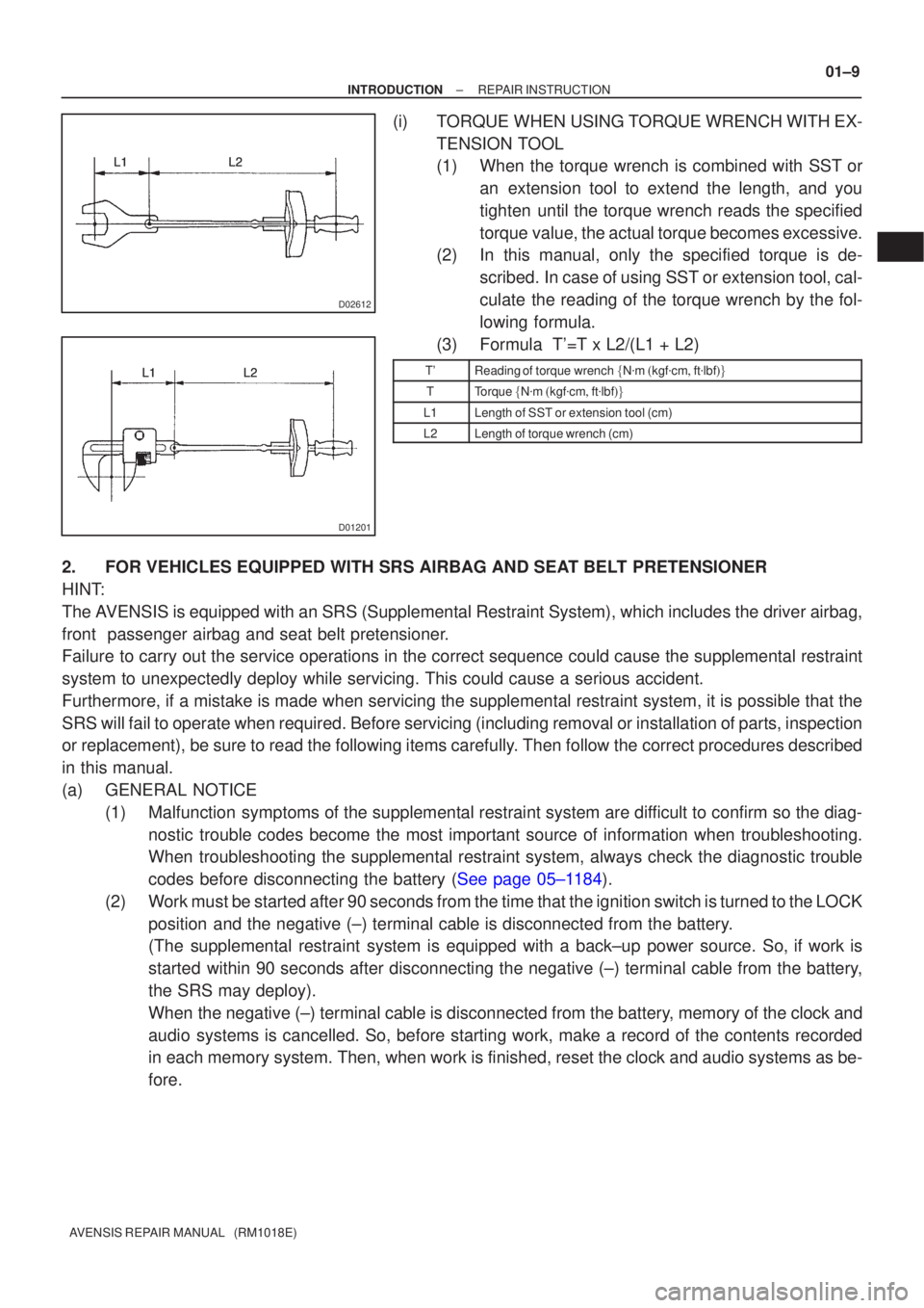
(i)TORQUE WHEN USING TORQUE WRENCH WITH EX-
TENSION TOOL
(1)When the torque wrench is combined with SST oran extension tool to extend the length, and you
tighten until the torque wrench reads the specified
torque value, the actual torque becomes excessive.
(2)In this manual, only the specified torque is de-
scribed. In case of using SST or extension tool, cal-
culate the reading of the torque wrench by the fol-
lowing formula.
(3)Formula T'=T x L2/(L1 + L2)
T'Reading of torque wrench �N �m �kgf �cm �ft �lbf ��
TTorque �N �m �kgf �cm �ft �lbf ��
L1Length of SST or extension tool (cm)
L2Length of torque wrench (cm)
2.FOR VEHICLES EQUIPPED WITH SRS AIRBAG AND SEAT BELT PRETENSIONER
HINT:
The AVENSIS is equipped with an SRS (Supplemental Restraint System), which \
includes the driver airbag,
front passenger airbag and seat belt pretensioner.
Failure to carry out the service operations in the correct sequence could cause\
the supplemental restraint
system to unexpectedly deploy while servicing. This could cause a seriou\
s accident.
Furthermore, if a mistake is made when servicing the supplemental restra\
int system, it is possible that the
SRS will fail to operate when required. Before servicing (including remova\
l or installation of parts, inspection
or replacement), be sure to read the following items carefully. Then follow the correct procedures described
in this manual.
(a)GENERAL NOTICE
(1)Malfunction symptoms of the supplemental restraint system are difficult to confirm so the diag-nostic trouble codes become the most important source of information when trou\
bleshooting.
When troubleshooting the supplemental restraint system, always check the dia\
gnostic trouble
codes before disconnecting the battery (See page 05±1184).
(2) Work must be started after 90 seconds from the time that the ignition switch\
is turned to the LOCK position and the negative (±) terminal cable is disconnected from the batte\
ry.
(The supplemental restraint system is equipped with a back±up power sourc\
e. So, if work is
started within 90 seconds after disconnecting the negative (±) terminal ca\
ble from the battery,
the SRS may deploy).
When the negative (±) terminal cable is disconnected from the battery, memory of the clock and
audio systems is cancelled. So, before starting work, make a record of the contents recorded
in each memory system. Then, when work is finished, reset the clock and audio systems as be-
fore.
Page 47 of 5135

01±18
± INTRODUCTIONREPAIR INSTRUCTION
AVENSIS REPAIR MANUAL (RM1018E)
NOTICE:
�Confirm that the VSC warning light blinks.
�VSC system will be reset when the engine is re-
started.
�Fasten the vehicle with lock chains.
(b) NOTICES OF RELATED OPERATIONS TO VSC
(1) Do not carry out unnecessary installation and re-
moval as it might disorder the adjustment of related
parts to VSC.
(2) Be sure to carry out the preparation for operation
and the confirmation of operation completion in ac-
cordance with the instruction of the text and when
the related operations to VSC are performed.
10. FOR VEHICLES EQUIPPED WITH CATALYTIC CONVERTER
CAUTION:
If a large amount of unburned gasoline flows into the converter, it may cause overheating and is a
fire hazard. To prevent this, observe the following precautions.
(a) Use only unleaded gasoline.
(b) Avoid prolonged idling.
Avoid idling the engine for more than 20 minutes.
(c) Avoid a spark jump test.
(1) Perform a spark jump test only when absolutely necessary. Perform this test as rapidly as pos-
sible.
(2) While testing, never race the engine.
(d) Avoid a prolonged engine compression measurement.
Engine compression measurements must be performed as rapidly as possible.
(e) Do not run the engine when the fuel tank is nearly empty. This may cause the engine to misfire and
create an extra load on the converter.
Page 479 of 5135

A01512
(V)
(3.96)
3.6
2.4
1.2
150 450
750(840)mmHg
kPa
20 60 100(112)
Manifold Absolute PressureOutput Voltage
05±342
± DIAGNOSTICSSFI SYSTEM (1AZ±FSE)
AVENSIS REPAIR MANUAL (RM1018E)
DTC P0105 MANIFOLD ABSOLUTE
PRESSURE/BAROMETRIC PRESSURE
CIRCUIT
DTC P0107 MANIFOLD ABSOLUTE
PRESSURE/BAROMETRIC PRESSURE
CIRCUIT LOW INPUT
DTC P0108 MANIFOLD ABSOLUTE
PRESSURE/BAROMETRIC PRESSURE
CIRCUIT HIGH INPUT
CIRCUIT DESCRIPTION
By a built±in sensor unit, the manifold absolute pressure sensor
detects the intake manifold pressure as a voltage. The ECM
then determines the basic injection duration and basic ignition
advance angle based on this voltage.
Since the manifold absolute pressure sensor does not use the
atmospheric pressure as a criterion, but senses the absolute
pressure inside the intake manifold (the pressure in proportion
to the preset absolute vacuum 0), it is not influenced by fluctua-
tions in the atmospheric pressure due to high altitude and other
factors. This permits it to control the air fuel ratio at the proper
level under all conditions.
If the ECM detects the DTC ºP0105, P0107 or P0108º, it oper-
ates the fail±safe function, keeping the ignition timing and fuel
injection volume constant and making it possible to drive the ve-
hicle.
DTC No.DTC Detection ConditionTrouble Area
P0105Open or short in manifold absolute pressure sensor circuit for
0.5 sec. or more
Open or short in manifold absolute pressure sensor circuit
P0107Open in manifold absolute pressure sensor circuit for 0.5 sec.
or more�Open or short in manifold absolute pressure sensor circuit
�Manifold absolute pressure sensor
�
ECM
P0108Short in manifold absolute pressure sensor circuit for 0.5 sec.
or more�ECM
HINT:
After confirming DTC ºP0105, P0107 or P0108º, use the hand±held tester to confirm the manifold absolute
pressure from ºDIAGNOSIS / OBD/MOBD / DATA LIST / ALLº.
Manifold Absolute Pressure (kPa)Malfunction
Approximately 0�PIM circuit short
142 or more
�VC circuit open or short
�PIM circuit open
�E2 circuit open
05CJF±01
Page 666 of 5135

A06532
1,900 4.5
1
13.3
100
kPa
mmHg
Air Pressure V
253.3
(3.9) (74.8) (in.Hg) 05±584
± DIAGNOSTICSECD SYSTEM (1CD±FTV)
AVENSIS REPAIR MANUAL (RM1018E)
DTC P0105 MANIFOLD ABSOLUTE
PRESSURE/BAROMETRIC PRESSURE
CIRCUIT
DTC P0107 MANIFOLD ABSOLUTE
PRESSURE/BAROMETRIC PRESSURE
CIRCUIT LOW INPUT
DTC P0108 MANIFOLD ABSOLUTE
PRESSURE/BAROMETRIC PRESSURE
CIRCUIT HIGH INPUT
CIRCUIT DESCRIPTION
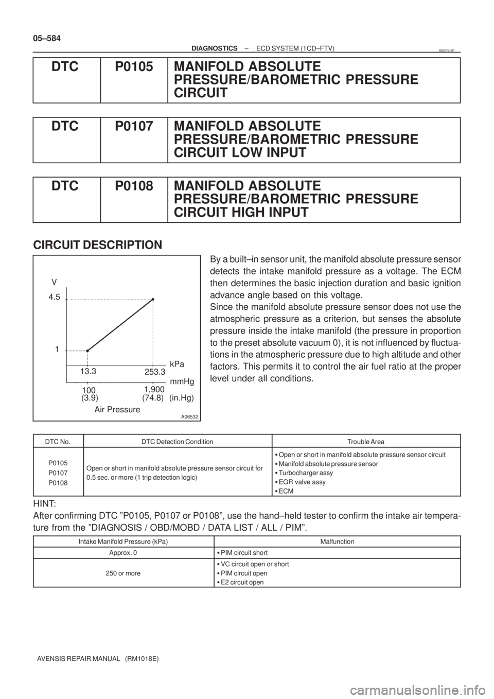
By a built±in sensor unit, the manifold absolute pressure sensor
detects the intake manifold pressure as a voltage. The ECM
then determines the basic injection duration and basic ignition
advance angle based on this voltage.
Since the manifold absolute pressure sensor does not use the
atmospheric pressure as a criterion, but senses the absolute
pressure inside the intake manifold (the pressure in proportion
to the preset absolute vacuum 0), it is not influenced by fluctua-
tions in the atmospheric pressure due to high altitude and other
factors. This permits it to control the air fuel ratio at the proper
level under all conditions.
DTC No.DTC Detection ConditionTrouble Area
P0105
P0107
P0108Open or short in manifold absolute pressure sensor circuit for
0.5 sec. or more (1 trip detection logic)
�Open or short in manifold absolute pressure sensor circuit
�Manifold absolute pressure sensor
�Turbocharger assy
�EGR valve assy
�ECM
HINT:
After confirming DTC ºP0105, P0107 or P0108º, use the hand±held tester to confirm the intake air tempera-
ture from the ºDIAGNOSIS / OBD/MOBD / DATA LIST / ALL / PIMº.
Intake Manifold Pressure (kPa)Malfunction
Approx. 0�PIM circuit short
250 or more
�VC circuit open or short
�PIM circuit open
�E2 circuit open
05CPJ±01
Page 927 of 5135
G23367
Tester menu flow:
± DIAGNOSTICSELECTRONIC CONTROLLED AUTOMATIC
TRANSAXLE [ECT] (U241E(1AZ±FE))05±875
AVENSIS REPAIR MANUAL (RM1018E)
11. RESET MEMORY
CAUTION:
Perform the RESET MEMORY (AT initialization) when replacing the automatic transaxle assy, engine
assy or ECM.
NOTICE:
Hand±held tester only
(a) Turn the ignition switch to OFF.
(b) Connect the hand±held tester to the DLC3.
(c) Turn the ignition switch to ON.
(d) Perform the reset memory procedure from the ENGINE menu.
CAUTION:
After performing the RESET MEMORY, be sure to perform the ROAD TEST described earlier.
Page 929 of 5135
05CBX±01
± DIAGNOSTICSELECTRONIC CONTROLLED AUTOMATIC
TRANSAXLE [ECT] (U241E(1AZ±FE))05±861
AVENSIS REPAIR MANUAL (RM1018E)
PRECAUTION
CAUTION:
Perform the RESET MEMORY (AT initialization) when replacing the automatic transaxle assy, engine
assy or ECM.
HINT:
Initialization can not be completed by only removing the battery.
Page 951 of 5135
G23367
Tester menu flow: 05±930
± DIAGNOSTICSELECTRONIC CONTROLLED AUTOMATIC
TRANSAXLE [ECT] (U241E(1AZ±FSE))
AVENSIS REPAIR MANUAL (RM1018E)
11. RESET MEMORY
CAUTION:
Perform the RESET MEMORY (AT initialization) when replacing the automatic transaxle assy, engine
assy or ECM.
NOTICE:
Hand±held tester only
(a) Turn the ignition switch to OFF.
(b) Connect the hand±held tester to the DLC3.
(c) Turn the ignition switch to ON.
(d) Perform the reset memory procedure from the ENGINE menu.
CAUTION:
After performing the RESET MEMORY, be sure to perform the ROAD TEST described earlier.
Page 953 of 5135
05CBY±01
05±918± DIAGNOSTICSELECTRONIC CONTROLLED AUTOMATIC
TRANSAXLE [ECT] (U241E(1AZ±FSE))
AVENSIS REPAIR MANUAL (RM1018E)
PRECAUTION
CAUTION:
Perform the RESET MEMORY (AT initialization) when replacing the automatic transaxle assy, engine
assy or ECM.
HINT:
Initialization can not be completed by only removing the battery.