Page 2459 of 5135
260DP±01
F44614
Front Shock Absorber with Coil Spring
Front Stabilizer Link Assy LH
47 (479, 35)
220 (2,240, 162)
74 (755, 55)
19 (194, 14)
Speed Sensor
Front LH
Front Flexible Hose
Front Suspension Support Dust Cover LH
Front Suspension Support Sub±assy LH
Front Suspension
Support LH Dust Seal
Front Coil Spring
Seat Upper LH
Front Axle Assy
Front Coil Spring Insulator Upper LH
Front Coil Spring LH
N�m (kgf�cm, ft�lbf) : Specified torque
�Non±reusable part
Front Spring
Bumper LH
Front Coil
Spring Insulator
Lower LH
Shock Absorber
Assy Front LH
39 (398, 29)
� 26±2
± FRONT SUSPENSIONFRONT SUSPENSION
AVENSIS REPAIR MANUAL (RM1018E)
FRONT SUSPENSION
COMPONENTS
Page 2461 of 5135
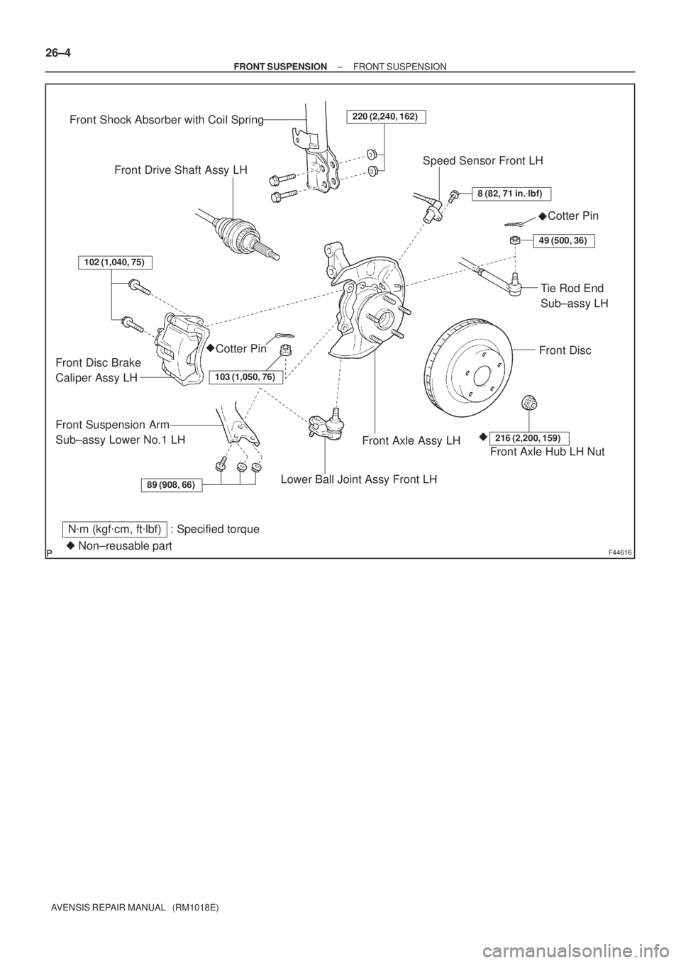
F44616
89 (908, 66)
102 (1,040, 75)
220 (2,240, 162)
8 (82, 71 in.�lbf)
49 (500, 36)
103 (1,050, 76)
216 (2,200, 159)
Front Shock Absorber with Coil Spring
Front Drive Shaft Assy LHSpeed Sensor Front LH
Cotter Pin
Front Disc
Tie Rod End
Sub±assy LH
Cotter Pin
Front Disc Brake
Caliper Assy LH
Front Suspension Arm
Sub±assy Lower No.1 LH
Lower Ball Joint Assy Front LH
Front Axle Assy LHFront Axle Hub LH Nut
N�m (kgf�cm, ft�lbf) : Specified torque
�Non±reusable part�
�� 26±4
± FRONT SUSPENSIONFRONT SUSPENSION
AVENSIS REPAIR MANUAL (RM1018E)
Page 2462 of 5135

F45154
Rack & Pinion
Power Steering Gear Assy
Tie Rod End
Sub±assy LH
Front Stabilizer Link
Assy LH
Stabilizer Bar Front Front Stabilizer Link
Assy RH
Front Suspension Arm
Sub±assy Lower No.1 RH
Front Suspension
Member Brace
Rear RHFront Stabilizer
Bar Bush No.1
Front Suspension
Crossmember Sub±assy
Front Suspension
Arm Sub±assy
Lower No.1 LH
Body Mounting
Stopper Rear
Front Suspension
Member Body
Mounting Stopper FR
Front Suspension
Member Brace Rear LH
Cotter Pin �
89 (908, 66)
133 (1,360, 98)
49 (500, 36)
74 (755, 55)
80 (816, 59)
133 (1,360, 98)
74 (755, 55)
49 (500, 36)
80 (816, 59)
19 (194, 14)
19 (194, 14)
133 (1,360, 98)
80 (816, 59)
133 (1,360, 98)
80 (816, 59)
19 (194, 14)
49 (500, 36)
74 (755, 55)
N�m (kgf�cm, ft�lbf) : Specified torque
Non±reusable part �
5.4 (55, 48 in.�lbf)w/ HID:
HID Height
Control Sensor
Front Stabilizer
Bracket No.1 RH
Front Stabilizer
Bracket No.1 LH
96 (979, 71)
80 (816, 59)
52 (530, 38)
± FRONT SUSPENSIONFRONT SUSPENSION
26±5
AVENSIS REPAIR MANUAL (RM1018E)
Page 2476 of 5135

(a)
(b)
(b)
(b)
A77904
(f)
(f)
(e)
(d)
Terminal Cap
19±20
±
STARTING & CHARGING GENERATOR ASSY(1AZ±FE/1AZ±FSE)
AVENSIS REPAIR MANUAL (RM1018E)
GENERATOR ASSY(1")
190NK±01
A78515
A78516
A77903
(a)
(a)
(b)
(b)
(b)
A77904
(f)
(f)
(e)
(d)
Terminal Cap
19±20
±
STARTING & CHARGING GENERATOR ASSY(1AZ±FE/1AZ±FSE)
AVENSIS REPAIR MANUAL (RM1018E)
GENERATOR ASSY(1AZ±FE/1AZ±FSE)
REPLACEMENT
1.REMOVE ENGINE UNDER COVER LH
(a)Remove the 6 screws and 5 clips, and then remove the engine under cover.
2.REMOVE ENGINE UNDER COVER RH
(a)Remove the 6 screws and the 3 clips, and then remove the engine under cover.
3.REMOVE RADIATOR SUPPORT OPENING COVER (See page 10±26)
4. REMOVE ENGINE ROOM COVER SIDE (See page 10±26)
5. REMOVE FAN AND GENERATOR V BELT SST 09249±63010
HINT:
�1AZ±FE: 14±105
�1AZ±FSE: 14±185
6. REMOVE GENERATOR ASSY
(a) Disconnect the 2 heated oxygen sensor connectors. (1AZ±FE (Unleaded Gasoline) or 1AZ±FSE)
(b) Remove the 2 connector clamps of the heated oxygen sensor and the wire harness clamp.
(1AZ±FE (Unleaded Gasoline) or 1AZ±FSE)
(c) Remove the terminal cap.
(d) Remove the nut and disconnect the generator wire.
(e) Disconnect the generator connector.
(f) Remove the 2 wire harness clamps.
Page 2477 of 5135

19±21
AVENSIS REPAIR MANUAL (RM1018E)
(g) Remove the 2 bolts, and then remove the generator.
(h) Remove the bolt, an")
A77905
A77906
A77905
A
B
± STARTING & CHARGINGGENERATOR ASSY (1AZ±FE/1AZ±FSE)
19±21
AVENSIS REPAIR MANUAL (RM1018E)
(g) Remove the 2 bolts, and then remove the generator.
(h) Remove the bolt, and then remove the wire harness
clamp bracket.
7. INSTALL GENERATOR ASSY
(a) Install the wire harness clamp bracket wire the bolt.
Torque: 8.4 N�m (86 kgf�cm, 74 in.�lbf)
(b) Install the generator the 2 bolts.
Torque:
52 N�m (530 kgf�cm, 38 ft�lbf) for bolt A
21 N�m (214 kgf�cm, 16 ft�lbf) for bolt B
(c) Install the 2 wire harness clamps.
(d) Connect the generator connector.
(e) Install the generator wire with the nut.
Torque: 9.8 N�m (100 kgf�cm, 7 ft�lbf)
(f) Install the terminal cap.
(g) Install the 2 connector clamps of the heated oxygen sen-
sor and the wire harness clamp.
(1AZ±FE (Unleaded Gasoline) or 1AZ±FSE)
(h) Connect the 2 heated oxygen sensor connectors.
(1AZ±FE (Unleaded Gasoline) or 1AZ±FSE)
8. INSTALL FAN AND GENERATOR V BELT
SST 09249±63010
HINT:
�1AZ±FE: 14±105
�1AZ±FSE: 14±185
9. INSTALL ENGINE ROOM COVER SIDE
10. INSTALL RADIATOR SUPPORT OPENING COVER
11. INSTALL ENGINE UNDER COVER RH
12. INSTALL ENGINE UNDER COVER LH
Page 2491 of 5135

REAR SHOCK ABSORBER WITH COIL SPRING
OVERHAUL
HINT:
COMPONENTS: See page 27±2.")
270E8±01
G25771
G25772
27±8
±
REAR SUSPENSION REAR SHOCK ABSORBER WITH COIL SPRING
AVENSIS REPAIR MANUAL (RM1018E)
REAR SHOCK ABSORBER WITH COIL SPRING
OVERHAUL
HINT:
COMPONENTS: See page 27±2.
1. REMOVE REAR DOOR SCUFF PLATE LH
2. REMOVE REAR SEAT CUSHION ASSEMBLY
(a)40/60 FOLDING FLIP±UP CUSHION (See page 72±21)
(b)40/60 FOLDING (See page 72±27)
(c)UNITED FIXED (See page 72±32)
3. REMOVE REAR SEATBACK ASSY
(a)40/60 FOLDING FLIP±UP CUSHION (See page 72±21)
(b)40/60 FOLDING (See page 72±27)
(c)UNITED FIXED (See page 72±32)
4. REMOVE REAR FLOOR FINISH PLATE (SEDAN MODELS)
5. REMOVE LUGGAGE COMPARTMENT TRIM COVER INNER LH (SEDAN MODELS)
6. REMOVE REAR FLOOR FINISH PLATE (LIFTBACK MODELS)
7.REMOVE DECK TRIM SIDE BOARD LH (LIFTBACK MODELS) (See page 76±45)
8. REMOVE REAR FLOOR FINISH PLATE (WAGON MODELS)
9.REMOVE DECK TRIM SIDE PANEL ASSY LH (WAGON MODELS) (See page 76±54)
10. REMOVE REAR WHEEL 11. DISCONNECT SKID CONTROL SENSOR WIRE
(a) Disconnect the skid control sensor connector.
(b) Remove the bolt and wire bracket.
12. SEPARATE REAR STABILIZER LINK ASSY LH
(a) Remove the nut, and separate the rear stabilizer link assyLH.
HINT:
If the ball joint turns together with the nut, use a hexagon (5 mm)
wrench to hold the stud.
13. SEPARATE REAR STABILIZER LINK ASSY RH
HINT:
Separate the RH side by the same procedures as the LH side.
Page 2495 of 5135

(c) Install the rear suspension arm assy No.1 LH with the 3
bolts.
Torque: 6")
G23868
G23867
G25772
G25771
27±12
± REAR SUSPENSIONREAR SHOCK ABSORBER WITH COIL SPRING
AVENSIS REPAIR MANUAL (RM1018E)
(c) Install the rear suspension arm assy No.1 LH with the 3
bolts.
Torque: 65 N�m (663 kgf�cm, 48 ft�lbf)
(d) Connect the parking brake cable assy No.3 with the 2
bolts.
Torque: 5.0 N�m (51 kgf�cm, 44 in.�lbf)
19. INSTALL REAR STABILIZER LINK ASSY LH
(a) Install the rear stabilizer link assy LH with the nut.
Torque: 44 N�m (449 kgf�cm, 32 ft�lbf)
HINT:
If the ball joint turns together with the nut, use a hexagon (5 mm)
wrench to hold the stud.
20. INSTALL REAR STABILIZER LINK ASSY RH
HINT:
Install the RH side by the same procedures as the LH side.
21. CONNECT SKID CONTROL SENSOR WIRE
(a) Install the wire bracket and bolt.
Torque: 5.0 N�m (51 kgf�cm, 44 in.�lbf)
(b) Connect the skid control sensor connector.
22. INSTALL REAR WHEEL
Torque: 103 N�m (1,050 kgf�cm, 76 ft�lbf)
23. STABILIZE SUSPENSION
(a) Bounce the vehicle up and down several times to stabilize the suspension.
Page 2496 of 5135
G23865
±
REAR SUSPENSION REAR SHOCK ABSORBER WITH COIL SPRING
27±13
AVENSIS REPAIR MANUAL (RM1018E)
24. FULLY TIGHTEN REAR SHOCK ABSORBER WITH
COIL SPRING
(a) Fully tighten the bolt and nut.
Torque: 160 N �m (1,632 kgf �cm, 118 ft �lbf)
NOTICE:
�When installing the bolt, hold the nut not to rotate.
�Be sure to empty the vehicle when fully tightening the
bolt and nut.
25.INSPECT AND ADJUST REAR WHEEL ALIGNMENT (See page 27±4)
26. CHECK ABS SPEED SENSOR SIGNAL
(a)ABD WITH EBD SYSTEM (See page 05±699)
(b)ABD WITH EBD & BA & TRC & VSC SYSTEM ( See page 05±756)

220 (2,240, 162)
74 (755, 55)
19 (194, 14)
Speed Sensor
Front LH
Front Flexible Hose
Front Suspension")

24. FULLY TIGHTEN REAR SHOCK ABSORBER WITH
COIL SPRING
(a) Fully tighten the bolt and nut.
Torqu")