Page 2522 of 5135
C80880
F13686
26±14
±
FRONT SUSPENSION FRONT SHOCK ABSORBER WITH COIL SPRING
AVENSIS REPAIR MANUAL (RM1018E)
(d) Install the flexible hose and ABS speed sensor wire har- ness bracket with the bolt.
Torque: 19 N �m (192 kgf �cm, 14 ft �lbf)
25. INSTALL FRONT STABILIZER LINK ASSY LH
(a) Install the stabilizer bar link with the nut. Torque: 74 N �m (755 kgf �cm, 55 ft �lbf)
HINT:
If the ball joint turns together with the nut, use a hexagon (6 mm)
wrench to hold the stud.
26. INSTALL FRONT WHEEL Torque: 103 N �m (1,050 kgf �cm, 76 ft �lbf)
27.INSPECT AND ADJUST FRONT WHEEL ALIGNMENT (See page 26±6)
Page 2528 of 5135

REPLACEMENT
HINT:
Replace the RH side by the same")
300JY±01
������F45751
SST
C80291
F44775
C67088
30±22
±
DRIVE SHAFT / PROPELLER SHAFT FRONT AXLE HUB SUB±ASSY LH
AVENSIS REPAIR MANUAL (RM1018E)
REPLACEMENT
HINT:
Replace the RH side by the same procedures as the LH side.
1. REMOVE FRONT WHEEL
2.SEPARATE FRONT STABILIZER LINK ASSY LH (See page 30±6) 3. REMOVE FRONT AXLE HUB LH NUT
(a) Using SST and a hammer, unstake the staked part of theaxle hub LH nut.
SST 09930±00010
(b) While applying the brakes, remove the axle hub LH nut.
4. DISCONNECT SPEED SENSOR FRONT LH
(a) Remove the bolt, and disconnect the speed sensor wire and flexible hose from the shock absorber.
(b) Remove the bolt, separate the speed sensor front LH from the steering knuckle.
NOTICE:
�Be careful not to damage the speed sensor.
�Prevent foreign matter from attaching to the speed
sensor.
5. SEPARATE FRONT DISC BRAKE CALIPER ASSY LH
(a) Removing the 2 bolts, separate the disc brake caliper assy LH from the steering knuckle.
NOTICE:
Use a string or other device to keep the brake caliper from
hanging down.
Page 2529 of 5135
F40217
SSTTurn
Hold
C80293
D27403
C83023
± DRIVE SHAFT / PROPELLER SHAFTFRONT AXLE HUB SUB±ASSY LH
30±23
AVENSIS REPAIR MANUAL (RM1018E)
6. REMOVE FRONT DISC
7. SEPARATE TIE ROD END SUB±ASSY LH
(a) Remove the cotter pin and nut.
(b) Using SST, separate the tie rod end sub±assy LH from the
steering knuckle.
SST 09628±62011
8. SEPARATE FRONT SUSPENSION ARM SUB±ASSY
LOWER NO.1 LH
(a) Remove the bolt and 2 nuts, and separate the suspension
arm sub±assy lower No.1 LH from the lower ball joint.
9. REMOVE FRONT AXLE ASSY LH
(a) Using a plastic hammer, separate the drive shaft assy LH
from the axle hub.
NOTICE:
Be careful not to damage the boot and ABS speed sensor
rotor.
(b) Remove the 2 bolts, nuts and steering knuckle with the
shock absorber.
Page 2532 of 5135

19.INSTALL LOWER BALL JOINT ASSY FRONT LH
(a)Install the lower ball joint and torque")
C83023
C80293
30±26
±
DRIVE SHAFT / PROPELLER SHAFT FRONT AXLE HUB SUB±ASSY LH
AVENSIS REPAIR MANUAL (RM1018E)
19.INSTALL LOWER BALL JOINT ASSY FRONT LH
(a)Install the lower ball joint and torque the nut. Torque: 103 N �m (1,050 kgf �cm, 76 ft �lbf)
(b)Install a new cotter pin.
NOTICE:
If the holes for the cotter pin are not aligned, tighten the nut up to 6\
0 � further.
20.INSTALL FRONT AXLE ASSY LH
(a)Install the 2 bolts, nuts and steering knuckle with 2 bolts and nuts to the shock absorber.
Torque: 220 N �m (2,243 kgf �cm, 162 ft �lbf)
NOTICE:
Only when reusing the bolts and nuts, apply engine oil to
the screw part of the nuts.
(b)Push the front axle assy toward the outside of the vehicle, fit the splined part of the drive shaft assy to that of the front
axle assy and insert the drive shaft assy into the front axle
assy.
NOTICE:
�Do not push out the front axle assy excessively.
�Be careful not to damage the drive shaft outboard
joint boot.
�Be careful not to damage the speed sensor rotor.
21.INSTALL FRONT SUSPENSION ARM SUB±ASSY LOWER NO.1 LH
(a)Install the front suspension arm sub±assy lower No.1 LH and lower ball joint with the 2 nuts and bolt.
Torque: 89 N �m (908 kgf �cm, 66 ft �lbf)
22.INSTALL TIE ROD END SUB±ASSY LH
(a)Install the tie rod end sub±assy LH to the steering knuckle.
(b)Install the nut and a new cotter pin. Torque: 49 N �m (500 kgf �cm, 36 ft �lbf)
NOTICE:
If the holes for the cotter pin are not aligned, tighten the nut up to 6\
0 � further.
23.INSTALL FRONT STABILIZER LINK ASSY LH (See page 30±6)
24. INSTALL FRONT DISC
Page 2533 of 5135

25. INSTALL FRONT DISC BRAKE CALIPER ASSY LH
(a) Install the disc brake calip")
C67088
F44775
C80291
±
DRIVE SHAFT / PROPELLER SHAFT FRONT AXLE HUB SUB±ASSY LH
30±27
AVENSIS REPAIR MANUAL (RM1018E)
25. INSTALL FRONT DISC BRAKE CALIPER ASSY LH
(a) Install the disc brake caliper assy with the 2 bolts to the
steering knuckle.
Torque: 104 N �m (1,040 kgf �cm, 75 ft �lbf)
26. INSTALL FRONT AXLE HUB LH NUT
(a) Using a socket wrench (30 mm), install a new axle hub LH nut. Torque: 216 N �m (2,200 kgf �cm, 159 ft �lbf)
27. SEPARATE FRONT DISC BRAKE CALIPER ASSY LH
(a) Removing the 2 bolts, separate the disc brake caliper assy from the stee\
ring knuckle.
NOTICE:
Use a string or other device to keep the brake caliper from hanging down\
.
28. REMOVE FRONT DISC
29.INSPECT BEARING BACKLASH (See page 30±2)
30.INSPECT AXLE HUB DEVIATION (See page 30±2)
31. INSTALL FRONT DISC
32. INSTALL FRONT DISC BRAKE CALIPER ASSY LH
(a) Install the disc brake caliper assy with the 2 bolts to the steering knu\
ckle. Torque: 104 N �m (1,040 kgf �cm, 75 ft �lbf)
33. CONNECT SPEED SENSOR FRONT LH
(a) Install the speed sensor front LH to the steering knuckle with the bolt.
Torque: 8.0 N �m (82 kgf �cm, 71 in. �lbf)
(b) Connect the speed sensor wire and flexible hose to the shock absorber with the bolt.
Torque: 19 N �m (194 kgf �cm, 14 ft �lbf)
NOTICE:
�Be careful not to damage the speed sensor.
�Keep the speed sensor clean.
�Do not twist the sensor wire when installing the sen-
sor.
Page 2534 of 5135
C68609
30±28
±
DRIVE SHAFT / PROPELLER SHAFT FRONT AXLE HUB SUB±ASSY LH
AVENSIS REPAIR MANUAL (RM1018E)
34. INSTALL FRONT AXLE HUB LH NUT
(a) While applying the brakes, install a new axle hub LH nut. Torque: 216 N �m (2,200 kgf �cm, 159 ft �lbf)
(b) Using a chisel and hammer, stake the axle hub LH nut.
35. INSTALL FRONT WHEEL Torque: 103 N �m (1,050 kgf �cm, 76 ft �lbf)
36.INSPECT AND ADJUST FRONT WHEEL ALIGNMENT (See page 26±6)
37. CHECK ABS SPEED SENSOR SIGNAL
(a)ABD WITH EBD SYSTEM (See page 05±699)
(b)ABD WITH EBD & BA & TRC & VSC SYSTEM ( See page 05±756)
Page 2535 of 5135
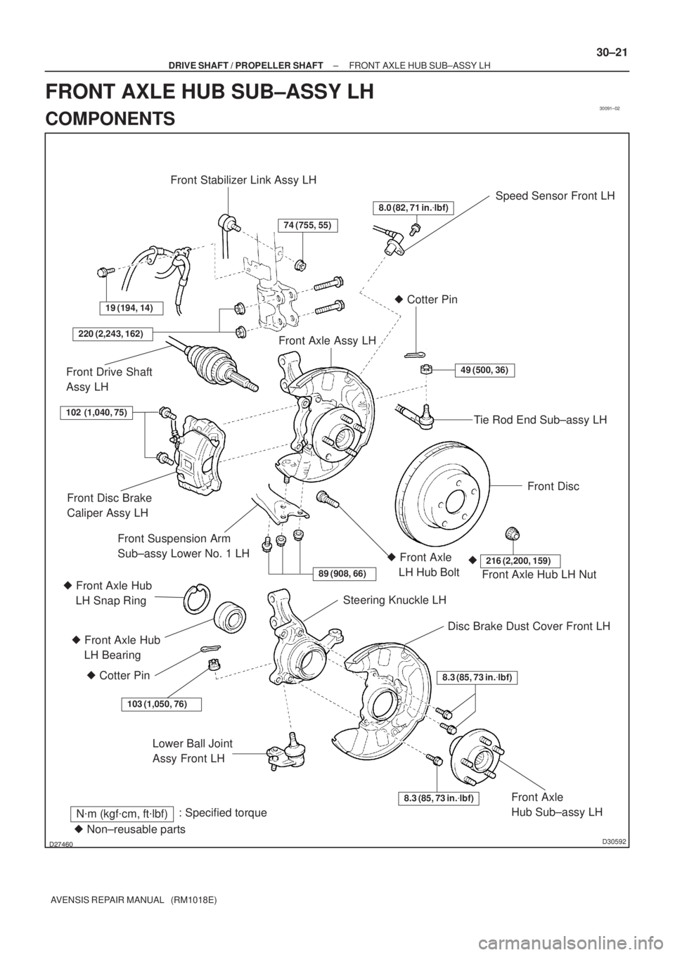
30091±02
������D30592
Speed Sensor Front LH
Lower Ball Joint
Assy Front LH
N�m (kgf�cm, ft�lbf): Specified torque
8.0 (82, 71 in.�lbf)
49 (500, 36)
Tie Rod End Sub±assy LH � Cotter Pin
Front Disc
Front Axle Assy LH
19 (194, 14)
Front Stabilizer Link Assy LH
74 (755, 55)
220 (2,243, 162)
Front Drive Shaft
Assy LH
Front Axle Hub LH Nut
216 (2,200, 159)�� Front Axle
LH Hub Bolt
89 (908, 66)
Steering Knuckle LH
Disc Brake Dust Cover Front LH
8.3 (85, 73 in.�lbf)
8.3 (85, 73 in.�lbf)Front Axle
Hub Sub±assy LH
Front Disc Brake
Caliper Assy LH
Front Suspension Arm
Sub±assy Lower No. 1 LH
� Front Axle Hub
LH Bearing
� Cotter Pin
103 (1,050, 76)
102 (1,040, 75)
� Non±reusable parts � Front Axle Hub
LH Snap Ring
± DRIVE SHAFT / PROPELLER SHAFTFRONT AXLE HUB SUB±ASSY LH
30±21
AVENSIS REPAIR MANUAL (RM1018E)
FRONT AXLE HUB SUB±ASSY LH
COMPONENTS
Page 2536 of 5135

OVERHAUL
HINT:
Overhaul the RH side by the same procedures")
300JX±01
������F45751
SST
F13686
Hold
Turn
C80291
30±6
± DRIVE SHAFT / PROPELLER SHAFTFRONT DRIVE SHAFT
AVENSIS REPAIR MANUAL (RM1018E)
OVERHAUL
HINT:
Overhaul the RH side by the same procedures as the LH side.
1. DRAIN AUTOMATIC TRANSAXLE FLUID (A/T TRANSAXLE)
(a) Remove the drain plug and gasket, and then drain the ATF.
(b) Install a new gasket and drain plug.
Torque: 49 N�m (500 kgf�cm, 36 ft�lbf)
2. DRAIN MANUAL TRANSAXLE OIL (M/T TRANSAXLE)
(a) Remove the filler plug and gasket.
(b) Remove the drain plug and gasket.
(c) Install 2 new gaskets, drain plug and filler plug.
Torque:
C50/C250: 39 N�m (400 kgf�cm, 29 ft�lbf)
E354/E357: 49 N�m (500 kgf�cm, 36 ft�lbf)
3. REMOVE FRONT WHEEL
4. REMOVE ENGINE UNDER COVER LH
5. SEPARATE FRONT AXLE HUB LH NUT
(a) Using SST and a hammer, unstake the staked part of the
nut.
SST 09930±00010
(b) While applying the brakes, remove the axle hub LH nut.
NOTICE:
Loosen the staked part of the lock nut completely, other-
wise the screw of the drive shaft may be damaged.
6. SEPARATE FRONT STABILIZER LINK ASSY LH
(a) Remove the nut and separate the front stabilizer link assy
LH from the shock absorber assy LH.
HINT:
If the ball joint turns together with the nut, use a hexagon
wrench (6 mm) to hold the stud.
7. DISCONNECT SPEED SENSOR FRONT LH
(a) Remove the bolt, disconnect the speed sensor wire and
flexible hose from the shock absorber.

(d) Install the flexible hose and ABS speed sensor wire har- ness bracket with the bolt")

6. REMOVE FRONT DISC
7. SEPARATE TIE ROD END SUB±ASSY LH")

34. INSTALL FRONT AXLE HUB LH NUT
(a) While applying the brakes, install a new axle hub LH")