Page 2537 of 5135

(b) Remove the bolt, and disconnect the speed sensor from
t")
F44775
F40217
SSTTurn
Hold
C80293
D27403
F40148SST
± DRIVE SHAFT / PROPELLER SHAFTFRONT DRIVE SHAFT
30±7
AVENSIS REPAIR MANUAL (RM1018E)
(b) Remove the bolt, and disconnect the speed sensor from
the steering knuckle.
NOTICE:
�Be careful not to damage the speed sensor.
�Prevent foreign matter from attaching to the speed
sensor.
8. SEPARATE TIE ROD END SUB±ASSY LH
(a) Remove the cotter pin and nut.
(b) Using SST, separate the tie rod end sub±assy LH from the
steering knuckle.
SST 09628±62011
9. SEPARATE FRONT SUSPENSION ARM SUB±ASSY
LOWER NO.1 LH
(a) Remove the bolt and 2 nuts, and separate the front sus-
pension arm sub±assy lower No.1 LH from the lower ball
joint.
10. SEPARATE FRONT AXLE ASSY LH
(a) Using a plastic hammer, separate the front drive shaft
assy LH from the axle hub.
NOTICE:
Be careful not to damage the boot and speed sensor rotor.
11. REMOVE FRONT DRIVE SHAFT ASSY LH
(a) Using SST, remove the front drive shaft assy LH.
SST 09520±01010, 09520±24010 (09520±32040)
NOTICE:
�Be careful not to damage the oil seal, boot and dust
cover.
�Be careful not to drop the drive shaft assy.
Page 2549 of 5135

44. INSTALL FRONT AXLE ASSY LH
(a) Install the drive shaft assy LH to the front axle ass")
C80293
F44775
C80291
± DRIVE SHAFT / PROPELLER SHAFTFRONT DRIVE SHAFT
30±19
AVENSIS REPAIR MANUAL (RM1018E)
44. INSTALL FRONT AXLE ASSY LH
(a) Install the drive shaft assy LH to the front axle assy LH.
NOTICE:
�Be careful not to damage the outboard joint boot.
�Be careful not to damage the speed sensor rotor.
45. INSTALL FRONT SUSPENSION ARM SUB±ASSY
LOWER NO.1 LH
(a) Install the lower ball joint to the front suspension arm sub±
assy lower No.1 LH with the bolt and 2 nuts.
Torque: 89 N�m (908 kgf�cm, 66 ft�lbf)
46. INSTALL TIE ROD END SUB±ASSY LH
(a) Install the tie rod end sub±assy LH to the steering knuckle with the nut.
Torque: 49 N�m (500 kgf�cm, 36 ft�lbf)
(b) Install a new cotter pin.
NOTICE:
If the holes for the cotter pin are not aligned, tighten the nut up to 60� further.
47. CONNECT SPEED SENSOR FRONT LH
(a) Install the speed sensor front LH to the steering knuckle
with the bolt.
Torque: 8.0 N�m (82 kgf�cm, 71 in.�lbf)
(b) Connect the speed sensor wire and flexible hose to the
shock absorber with the bolt.
Torque: 19 N�m (194 kgf�cm, 14 ft�lbf)
NOTICE:
�Be careful not to damage the speed sensor.
�Keep the speed sensor clean.
�Do not twist the sensor wire when installing the sen-
sor.
Page 2550 of 5135

48.INSTALL FRONT STABILIZER LINK ASSY LH
(a)Install the front stabilizer link assy LH")
F13686
HoldTurn
C68609
30±20
±
DRIVE SHAFT / PROPELLER SHAFT FRONT DRIVE SHAFT
AVENSIS REPAIR MANUAL (RM1018E)
48.INSTALL FRONT STABILIZER LINK ASSY LH
(a)Install the front stabilizer link assy LH with the nut. Torque: 74 N �m (755 kgf �cm, 55 ft �lbf)
HINT:
If the ball joint turns together with the nut, use a hexagon
wrench (6 mm) to hold the stud.
49.INSTALL FRONT AXLE HUB LH NUT
(a)Install a new axle hub LH nut. Torque: 216 N �m (2,200 kgf �cm, 159 ft �lbf)
(b)Using a chisel and hammer, stake the axle hub LH nut.
50.INSTALL ENGINE UNDER COVER LH
51.INSTALL FRONT WHEEL Torque: 103 N �m (1,050 kgf �cm, 76 ft �lbf)
52.ADD AUTOMATIC TRANSAXLE FLUID (A/T TRANSAXLE)
53.INSPECT AND ADJUST AUTOMATIC TRANSAXLE FLUID (A/T TRANSAXLE) (See page 40±2)
54. ADD MANUAL TRANSAXLE OIL (M/T TRANSAXLE)
55.INSPECT MANUAL TRANSAXLE OIL (M/T TRANSAXLE) (See page 41±2)
56.INSPECT AND ADJUST FRONT WHEEL ALIGNMENT (See page 26±6)
57. CHECK ABS SPEED SENSOR SIGNAL
(a)ABD WITH EBD SYSTEM (See page 05±699)
(b)ABD WITH EBD & BA & TRC & VSC SYSTEM ( See page 05±756)
Page 2551 of 5135
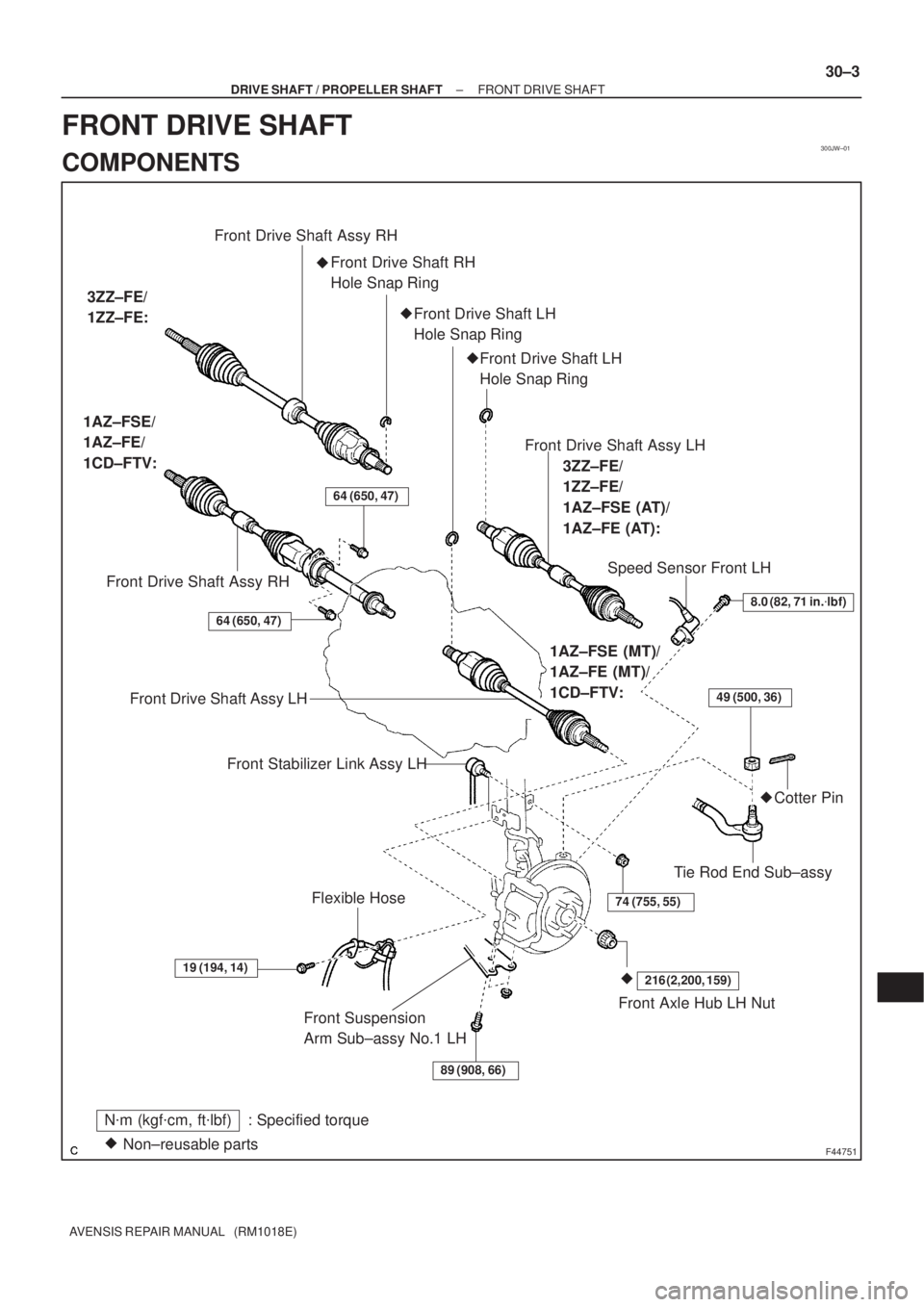
300JW±01
F44751
N�m (kgf�cm, ft�lbf) : Specified torque
Non±reusable parts �Front Suspension
Arm Sub±assy No.1 LH
89 (908, 66)
19 (194, 14)
74 (755, 55)
64 (650, 47)
49 (500, 36)
216 (2,200, 159)�
Front Axle Hub LH Nut Flexible Hose
Tie Rod End Sub±assy�Cotter Pin �Front Drive Shaft RH
Hole Snap Ring Front Drive Shaft Assy RH
Front Drive Shaft Assy RH 1AZ±FSE/
1AZ±FE/
1CD±FTV:
Speed Sensor Front LH
8.0 (82, 71 in.�lbf)
Front Drive Shaft Assy LH
Front Stabilizer Link Assy LH
3ZZ±FE/
1ZZ±FE:
64 (650, 47)
Front Drive Shaft Assy LH
3ZZ±FE/
1ZZ±FE/
1AZ±FSE (AT)/
1AZ±FE (AT):
1AZ±FSE (MT)/
1AZ±FE (MT)/
1CD±FTV:
�Front Drive Shaft LH
Hole Snap Ring
�Front Drive Shaft LH
Hole Snap Ring
± DRIVE SHAFT / PROPELLER SHAFTFRONT DRIVE SHAFT
30±3
AVENSIS REPAIR MANUAL (RM1018E)
FRONT DRIVE SHAFT
COMPONENTS
Page 2562 of 5135
270E4±01
G23906
G25775
G23871
������G25777
27±24
±
REAR SUSPENSION LOWER CONTROL ARM ASSY LH
AVENSIS REPAIR MANUAL (RM1018E)
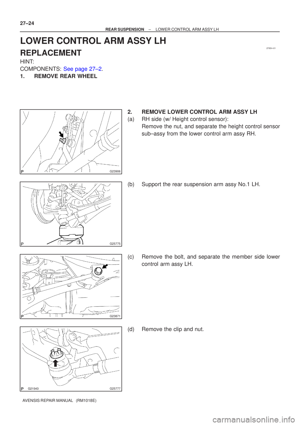
LOWER CONTROL ARM ASSY LH
REPLACEMENT
HINT:
COMPONENTS: See page 27±2.
1. REMOVE REAR WHEEL 2. REMOVE LOWER CONTROL ARM ASSY LH
(a) RH side (w/ Height control sensor):Remove the nut, and separate the height control sensor
sub±assy from the lower control arm assy RH.
(b) Support the rear suspension arm assy No.1 LH.
(c) Remove the bolt, and separate the member side lower control arm assy LH.
(d) Remove the clip and nut.
Page 2564 of 5135
G23871
G23906
27±26
±
REAR SUSPENSION LOWER CONTROL ARM ASSY LH
AVENSIS REPAIR MANUAL (RM1018E)
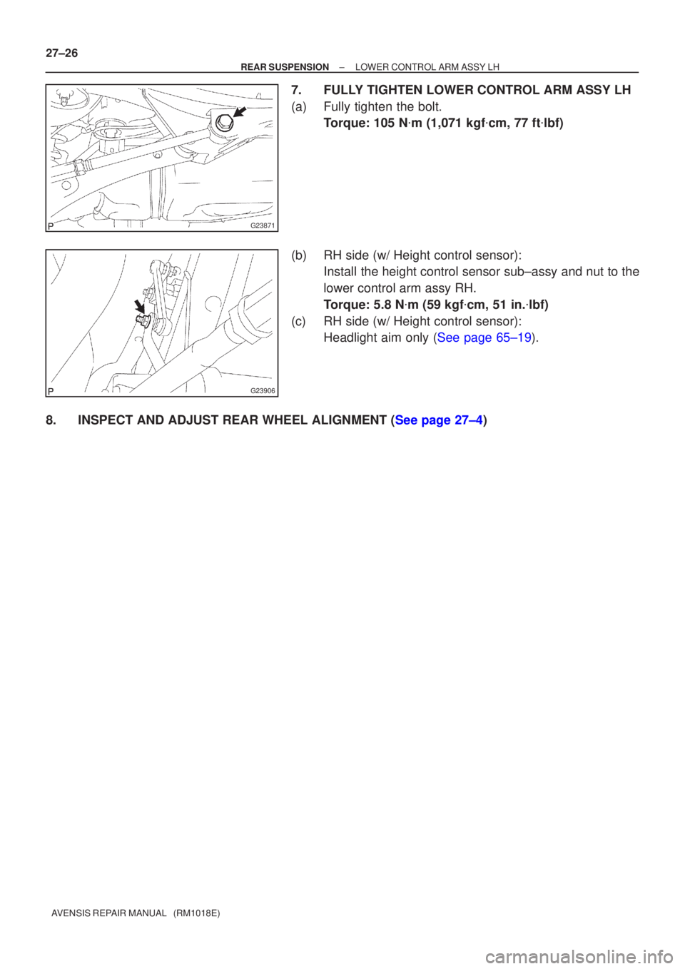
7. FULLY TIGHTEN LOWER CONTROL ARM ASSY LH
(a) Fully tighten the bolt. Torque: 105 N �m (1,071 kgf �cm, 77 ft �lbf)
(b) RH side (w/ Height control sensor): Install the height control sensor sub±assy and nut to the
lower control arm assy RH.
Torque: 5.8 N �m (59 kgf �cm, 51 in. �lbf)
(c) RH side (w/ Height control sensor): Headlight aim only (See page 65±19).
8.INSPECT AND ADJUST REAR WHEEL ALIGNMENT (See page 27±4)
Page 2565 of 5135
270E3±01
G23867
G25771
G25772
G25775
±
REAR SUSPENSION REAR SUSPENSION ARM ASSY NO.1 LH
27±15
AVENSIS REPAIR MANUAL (RM1018E)
REAR SUSPENSION ARM ASSY NO.1 LH
OVERHAUL
HINT:
COMPONENTS: See page 27±2.
1. REMOVE REAR WHEEL
2. SEPARATE PARKING BRAKE CABLE ASSY NO.3
(a) Remove the 2 bolts, and separate the parking brake cableassy No.3.
3. DISCONNECT SKID CONTROL SENSOR WIRE
(a) Disconnect the skid control sensor connector.
(b) Remove the bolt and wire bracket.
4. SEPARATE REAR STABILIZER LINK ASSY LH
(a) Remove the nut, and separate the rear stabilizer link assy LH.
HINT:
If the ball joint turns together with the nut, use a hexagon (5 mm)
wrench to hold the stud.
5. REMOVE LOWER CONTROL ARM ASSY LH
(a) Support the rear suspension arm assy No.1 LH.
Page 2571 of 5135
G23871
G23872
G25772
G25771
G23867
± REAR SUSPENSIONREAR SUSPENSION ARM ASSY NO.1 LH
27±21
AVENSIS REPAIR MANUAL (RM1018E)
10. INSTALL LOWER CONTROL ARM ASSY LH
(a) Install the lower control arm assy LH, and temporarily
tighten the bolt.
(b) Install the lower control arm assy LH to the rear axle carri-
er LH, and temporarily tighten the nut.
11. INSTALL REAR STABILIZER LINK ASSY LH
(a) Install the rear stabilizer link assy LH with the nut.
Torque: 44 N�m (449 kgf�cm, 32 ft�lbf)
HINT:
If the ball joint turns together with the nut, use a hexagon (5
mm) wrench to hold the stud.
12. CONNECT SKID CONTROL SENSOR WIRE
(a) Install the wire bracket and bolt.
Torque: 5.0 N�m (51 kgf�cm, 44 in.�lbf)
(b) Connect the skid control sensor connector.
13. INSTALL PARKING BRAKE CABLE ASSY NO.3
(a) Connect the parking brake cable assy No.3 with the 2
bolts.
Torque: 5.0 N�m (51 kgf�cm, 44 in.�lbf)

REAR SUSPENSION ARM ASSY NO.1 LH
OVERHAUL
HINT:
COMPONENTS: See page")

10. INSTALL LOWER CONTROL ARM ASSY LH
(a) Install the lower control arm a")