Page 2501 of 5135

80 (816, 59)
Rear Suspension Member Sub±assy
Rear Shock Absorber
Cushion Washer No.1
Coil Rear Spring
Rear Coil Spring Insulator")
270E0±01
������G26285
w/ Height Control Sensor:
5.8 (59, 51 in.�lbf)
80 (816, 59)
Rear Suspension Member Sub±assy
Rear Shock Absorber
Cushion Washer No.1
Coil Rear Spring
Rear Coil Spring Insulator Upper LH
Rear Spring Bumper No.1 LH
Rear Suspension Support Assy LH
Rear Spring Front Bracket
Sub±assy LH
Rear Shock
Absorber Cushion No.1
Lower Control Arm Assy RH
Rear Shock Absorber
Assy LH
160 (1,632, 118)
110 (1,122, 81)
65 (663, 48)
Rear Suspension
Support Stopper
Rear Suspension Arm
Bracket Assy LH
Rear Suspension
Arm Bush No.1�Camber Adjust Cam Assy
Rear Suspension Arm Assy No.1 LH
74 (755, 55)
105 (1,071, 77)
44 (449, 32)
74 (755, 55)
74 (755, 55)
Parking Brake Cable Assy No.3
5.0 (51, 44 in.�lbf)Rear Axle Carrier Sub±assy LH
Skid Control Sensor Wire
74 (755, 55)
Upper Control Arm Assy
Camber Adjust Cam No.2
Lower Control Arm Assy LH
105 (1,071, 77)
5.0 (51, 44 in.�lbf)
60 (612, 44)
N�m (kgf�cm, ft�lbf) : Specified torque
Non±reusable part �
56 (571, 41)
�56 (571, 41)
Clip
Clip 27±2
± REAR SUSPENSIONREAR SUSPENSION
AVENSIS REPAIR MANUAL (RM1018E)
REAR SUSPENSION
COMPONENTS
Page 2505 of 5135

10. SUSPEND ENGINE ASSY
(a)1ZZ, 3ZZ Engine: See page 41±15
(b)1AZ Engine: Se")
F45155
������F40197
Inner SideRear
Side
±
FRONT SUSPENSION STABILIZER BAR FRONT
26±27
AVENSIS REPAIR MANUAL (RM1018E)
10. SUSPEND ENGINE ASSY
(a)1ZZ, 3ZZ Engine: See page 41±15
(b)1AZ Engine: See page 41±24
(c)1CD Engine: See page 41±33
11.REMOVE FRONT SUSPENSION MEMBER BRACE REAR LH (See page 26±16)
12. REMOVE FRONT SUSPENSION MEMBER BRACE REAR RH
HINT:
Remove the RH side by the same procedures as the LH side.
13.SEPARATE FRONT SUSPENSION CROSSMEMBER SUB±ASSY (See page 26±16)
14. REMOVE FRONT STABILIZER BRACKET NO.1 LH
(a) Remove the 2 bolts and the front stabilizer bracket No.1 LH.
15. REMOVE FRONT STABILIZER BRACKET NO.1 RH
(a) w/ HID:Remove the 3 bolts, the front stabilizer bracket No.1 RH
and the height control sensor (Front).
(b) w/o HID:
Remove the 2 bolts and the front stabilizer bracket No.1
RH.
16. REMOVE FRONT STABILIZER BAR BUSH NO.1
(a) Remove the 2 bushings from the stabilizer bar.
17. REMOVE STABILIZER BAR FRONT
18. INSTALL STABILIZER BAR FRONT 19. INSTALL FRONT STABILIZER BAR BUSH NO.1
(a) Install the 2 front stabilizer bar bush No.1 to the stabilizerbar front as shown in the illustration.
HINT:
Install the bushing to the outer side of the bushing stopper on
the stabilizer bar.
20. INSTALL FRONT STABILIZER BRACKET NO.1 LH
(a) Install the front stabilizer bracket No.1 LH with the 2 bolts. Torque: 19 N �m (194 kgf �cm, 14 ft �lbf)
Page 2506 of 5135

21. INSTALL FRONT STABILIZER BRACKET NO.1 RH
(a) w/ HID: Install the front stabilizer bracket No.1 R")
F45155
A
B
F44620
26±28
±
FRONT SUSPENSION STABILIZER BAR FRONT
AVENSIS REPAIR MANUAL (RM1018E)
21. INSTALL FRONT STABILIZER BRACKET NO.1 RH
(a) w/ HID: Install the front stabilizer bracket No.1 RH and the height
control sensor (Front) with the 3 bolts.
Torque:
Bolt A: 5.4 N �m (55 kgf �cm, 48 in. �lbf)
Bolt B: 19 N �m (194 kgf �cm, 14 ft �lbf)
(b) w/o HID: Install the front stabilizer bracket No.1 RH with the 2 bolts.
Torque: 19 N �m (194 kgf �cm, 14 ft �lbf)
22.INSTALL FRONT SUSPENSION CROSSMEMBER SUB±ASSY (See page 26±16)
23.INSTALL FRONT SUSPENSION MEMBER BRACE REAR LH (See page 26±16)
24. INSTALL FRONT SUSPENSION MEMBER BRACE REAR RH
HINT:
Install the RH side by the same procedures as the LH side.
25. INSTALL RACK & PINION POWER STEERING GEAR ASSY
(a)Electric power steering model: See page 51±28
(b)Oil pressure power steering model: See page 51±36
26.INSTALL FRONT SUSPENSION ARM SUB±ASSY LOWER NO.1 LH (See page 30±6)
27. INSTALL FRONT SUSPENSION ARM SUB±ASSY LOWER NO.1 RH
HINT:
Connect the RH side by the same procedures as the LH side.
28.INSTALL TIE ROD END SUB±ASSY LH (See page 30±6)
29. INSTALL TIE ROD END SUB±ASSY RH
HINT:
Connect the RH side by the same procedures as the LH side.
30. INSTALL FRONT STABILIZER LINK ASSY LH
(a) Install the front stabilizer link assy LH with the 2 nuts.Torque: 74 N �m (755 kgf �cm, 55 ft �lbf)
HINT:
If the ball joint turns together with the nut, use a hexagon
wrench (6 mm) to hold the stud.
31. INSTALL FRONT STABILIZER LINK ASSY RH
HINT:
Install the RH side by the same procedures as the LH side.
32. INSTALL FRONT WHEEL Torque: 103 N �m (1,050 kgf �cm, 76 ft �lbf)
33.INSPECT AND ADJUST FRONT WHEEL ALIGNMENT (See page 26±6)
34.HEADLIGHT AIM ONLY (W/ DISCHARGE HEAD LAMP) (See page 65±19)
Page 2507 of 5135

LOWER BALL JOINT ASSY FRONT LH
REPLACEMENT
HINT:
�COMPONENTS: See page 26")
260DS±01
G22708
F40228
SST
ZX1712
26±24
±
FRONT SUSPENSION LOWER BALL JOINT ASSY FRONT LH
AVENSIS REPAIR MANUAL (RM1018E)
LOWER BALL JOINT ASSY FRONT LH
REPLACEMENT
HINT:
�COMPONENTS: See page 26±2
�Replace the RH side by the same procedures as the LH side. 1. INSPECT LOWER BALL JOINT ASSY FRONT LH
(a) Jack up front side of the vehicle.
(b) Check that there is no looseness on the ball joint by shak-ing the lower arm up and down with a force of 294 N (30
kgf, 66 lbf).
2. REMOVE FRONT WHEEL
3.SEPARATE FRONT AXLE HUB LH NUT (See page 30±6) SST 09930±00010
4.DISCONNECT SPEED SENSOR FRONT LH (See page 30±6)
5.SEPARATE FRONT DISC BRAKE CALIPER ASSY LH (See page 30±22)
6. REMOVE FRONT DISC
7.SEPARATE TIE ROD END SUB±ASSY LH (See page 30±22) SST 09628±62011
8.SEPARATE FRONT SUSPENSION ARM SUB±ASSY LOWER NO.1 LH (See page 30±22)
9.REMOVE FRONT AXLE ASSY LH (See page 30±22)
10. REMOVE LOWER BALL JOINT ASSY FRONT LH
(a) Remove the cotter pin and nut.
(b) Using SST, remove the lower ball joint assy front LH.
11. INSPECT LOWER BALL JOINT ASSY FRONT LH
(a) As shown in the illustration, flip the ball joint stud back andforth 5 times, before installing the nut.
(b) Using a torque wrench, turn the nut continuously at a rate of 3 ± 5 seconds per 1 turn and take the torque reading
on the 5th turn.
Turning torque:
0.98 ± 4.9 N´m (10 ± 50 kgf´cm, 9 ± 43 in.´lbf)
Page 2508 of 5135
±
FRONT SUSPENSION LOWER BALL JOINT ASSY FRONT LH
26±25
AVENSIS REPAIR MANUAL (RM1018E)
12. INSTALL LOWER BALL JOINT ASSY FRONT LH
(a) Install the lower ball joint assy front LH, and torque the nut.
Torque: 103 N �m (1,050 kgf �cm, 76 ft �lbf)
(b) Install a new cotter pin.
NOTICE:
If the holes for the cotter pin are not aligned, tighten the nut further\
up to 60 �.
13.INSTALL FRONT AXLE ASSY LH (See page 30±22)
14.INSTALL FRONT SUSPENSION ARM SUB±ASSY LOWER NO.1 LH (See page 30±22)
15.INSTALL TIE ROD END SUB±ASSY LH (See page 30±22)
16. INSTALL FRONT DISC
17.INSTALL FRONT DISC BRAKE CALIPER ASSY LH (See page 30±22)
18.CONNECT SPEED SENSOR FRONT LH (See page 30±6)
19.INSTALL FRONT AXLE HUB LH NUT (See page 30±6)
20. INSTALL FRONT WHEEL
Torque: 103 N �m (1,050 kgf �cm, 76 ft �lbf)
21.INSPECT AND ADJUST FRONT WHEEL ALIGNMENT (See page 26±6)
22. CHECK ABS SPEED SENSOR SIGNAL
(a)w/o VSC: See page 05±699
(b)w/ VSC: See page 05±756
Page 2513 of 5135
26±17
AVENSIS REPAIR MANUAL (RM1018E)
10. REMOVE FRONT SUSPENSION MEMBER BRACE
REAR LH
(a) Support")
C95317
C86742
C87504
C95318
± FRONT SUSPENSIONFRONT SUSPENSION ARM SUB±ASSY LOWER NO.1
LH (ATM)26±17
AVENSIS REPAIR MANUAL (RM1018E)
10. REMOVE FRONT SUSPENSION MEMBER BRACE
REAR LH
(a) Support the front suspension crossmember sub±assy
with a transmission jack.
(b) Remove the 4 bolts and front suspension member brace
rear LH.
(c) Remove the front suspension member body mounting
stopper rear from the front suspension member brace
rear LH.
11. REMOVE FRONT SUSPENSION MEMBER BRACE REAR RH
HINT:
Remove the RH side by the same procedures as the LH side.
12. SEPARATE FRONT SUSPENSION CROSSMEMBER
SUB±ASSY
(a) w/ HID:
Disconnect the height control sensor (Front) connector.
(b) Remove the 3 bolts and 3 nuts, disconnect the transverse
engine engine mounting insulator and engine mounting
member sub±assy center from the front suspension
crossmember sub±assy.
(c) Remove the 2 nuts and 2 front suspension member body
mounting stoppers front.
(d) Lower the transmission jack, remove the front suspension
crossmember sub±assy.
13. REMOVE FRONT SUSPENSION ARM SUB±ASSY
LOWER NO.1 LH
(a) Remove the 2 bolts, nut and lower suspension arm sub±
assy lower No.1 LH from the front suspension crossmem-
ber sub±assy.
Page 2514 of 5135

AVENSIS REPAIR MANUAL (RM1018E)
14.TEMPORARILY TIGHTEN FRONT SUSPENSION ARM S")
C95318
C87504
C86742
AA
AAB
B
C95317
AA
A
B
26±18
±
FRONT SUSPENSION FRONT SUSPENSION ARM SUB±ASSY LOWER NO.1
LH(ATM)
AVENSIS REPAIR MANUAL (RM1018E)
14.TEMPORARILY TIGHTEN FRONT SUSPENSION ARM SUB±ASSY LOWER NO.1 LH
(a)Install the lower suspension arm sub±assy lower No.1
LH, and temporarily tighten the 2 bolts and nut.
15.INSTALL FRONT SUSPENSION CROSSMEMBER SUB±ASSY
(a)Support the front suspension crossmember sub±assy with a transmission jack.
(b)Install the 2 front suspension member body mounting stoppers front and 2 nuts.
Torque: 133 N �m (1,360 kgf �cm, 98 ft �lbf)
(c)Connect the transverse engine engine mounting insula- tor and engine mounting member sub±assy center to the
front suspension crossmember sub±assy.
(d)Install the 3 bolts and 3 nuts. Torque:
Bolt A: 52 N �m (530 kgf �cm, 38 ft �lbf)
Bolt B: 96 N �m (979 kgf �cm, 71 ft �lbf)
(e)w/ HID: Connect the height control sensor (Front) connector.
16.INSTALL FRONT SUSPENSION ME MBER BRACE
REAR LH
(a)Install the front suspension member body mounting stop- per rear to the front suspension member brace rear LH.
(b)Install the 4 bolts and front suspension member brace rear LH.
Torque:
Bolt A: 80 N �m (816 kgf �cm, 59 ft �lbf)
Bolt B: 133 N �m (1,360 kgf �cm, 98 ft �lbf)
17.INSTALL FRONT SUSPENSION MEMBER BRACE REAR RH
HINT:
Install the RH side by the same procedures as the LH side.
18.CONNECT RACK & PINION POWER STEERING GEAR ASSY
(a)Electric power steering model: See page 51±28
(b)Oil pressure power steering model: See page 51±36
Page 2518 of 5135
2600M±04
F13686
C80880
F13683
F44622
26±10
±
FRONT SUSPENSION FRONT SHOCK ABSORBER WITH COIL SPRING
AVENSIS REPAIR MANUAL (RM1018E)
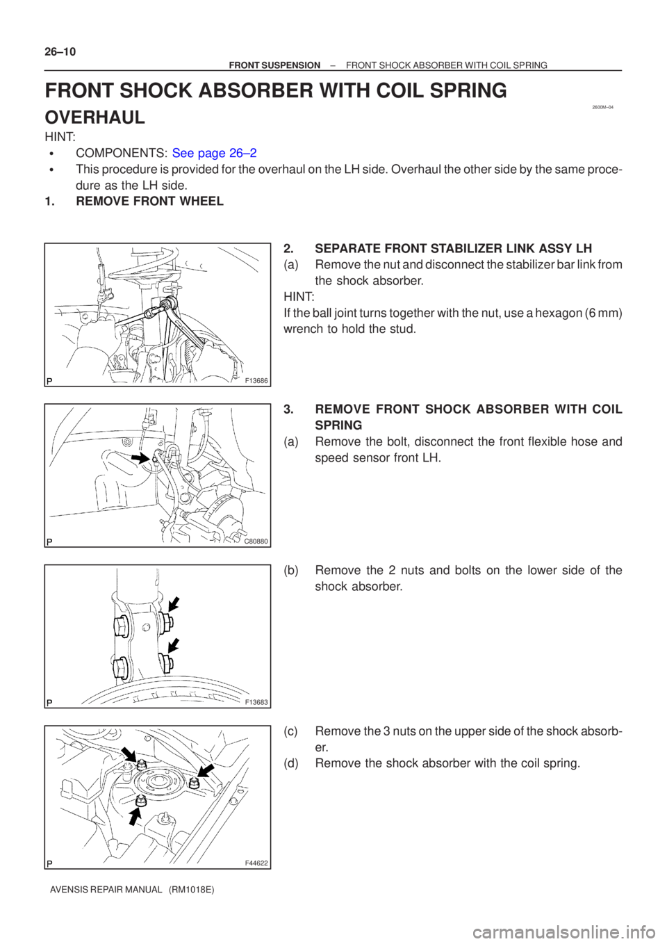
FRONT SHOCK ABSORBER WITH COIL SPRING
OVERHAUL
HINT:
�COMPONENTS: See page 26±2
�This procedure is provided for the overhaul on the LH side. Overhaul the oth\
er side by the same proce-
dure as the LH side.
1. REMOVE FRONT WHEEL
2. SEPARATE FRONT STABILIZER LINK ASSY LH
(a) Remove the nut and disconnect the stabilizer bar link fromthe shock absorber.
HINT:
If the ball joint turns together with the nut, use a hexagon (6 mm)
wrench to hold the stud.
3. REMOVE FRONT SHOCK ABSORBER WITH COIL SPRING
(a) Remove the bolt, disconnect the front flexible hose and speed sensor front LH.
(b) Remove the 2 nuts and bolts on the lower side of the shock absorber.
(c) Remove the 3 nuts on the upper side of the shock absorb- er.
(d) Remove the shock absorber with the coil spring.

12. INSTALL LOWER BALL JOINT ASSY FRONT LH
(a) Install the lower ball joint assy front LH, and torque the nu")