Page 3716 of 5135

A01185
A57508
Piston Bushing
Inside Diameter
Mark
Piston Pin
Diameter
Color
Connecting Rod
Bushing Inside Diameter Mark Front Mark
Front Mark
Z00064
14±48
± ENGINE MECHANICALCYLINDER BLOCK (1AZ±FE)
1AZ±FE ENGINE REPAIR MANUAL (RM865E)
(c) Using a caliper gauge, measure the inside diameter of the
connecting rod bushing.
Bushing inside diameter:
22.005 ± 22.014 mm (0.8663 ± 0.8667 in.)
Bushing inside diameter
Markmm (in.)
A22.005 ± 22.008 (0.8663 ± 0.8665)
B22.008 ± 22.011 (0.8665 ± 0.8666)
C22.011 ± 22.014 (0.8666 ± 0.8667)
(d) Subtract the piston pin diameter measurement from the
piton pin hole diameter measurement.
Standard oil clearance:
0.001 ± 0.007 mm (0.00004 ± 0.00028 in.)
Maximum oil clearance: 0.010 mm (0.0020 in.)
(e) If the oil clearance is greater than maximum, replace the
connecting rod. If necessary, replace the piston and pis-
ton pin as a set.
(f) Subtract the piston pin diameter measurement form the
bushing inside diameter measurement.
Standard oil clearance:
0.005 ± 0.011 mm (0.0002 ± 0.0004 in.)
Maximum oil clearance: 0.010 mm (0.0020 in.)
(g) If the oil clearance is greater than maximum, replace the
connecting rod. If necessary, replace the connecting rod
and piston pin as a set.
21. INSPECT CONNECTING ROD SUB±ASSY
(a) Using a rod aligner and feeler gauge, check the connect-
ing rod alignment.
(1) Check for out±of±alignment.
Maximum out±of±alignment:
0.05 mm (0.0020 in.) per 100 mm (3.94 in.)
(b) If out±of alignment is greater than maximum, replace the
connecting rod assembly.
Page 3719 of 5135

14±51
1AZ±FE ENGINE REPAIR MANUAL (RM865E)
26. INSPECT CRANKSHAFT OIL CLEARANCE
NOTICE:
�Clean the bac")
A53029
A13854
A13868
A13987
1
2 3
45
6 7
89
10 7
± ENGINE MECHANICALCYLINDER BLOCK (1AZ±FE)
14±51
1AZ±FE ENGINE REPAIR MANUAL (RM865E)
26. INSPECT CRANKSHAFT OIL CLEARANCE
NOTICE:
�Clean the backside of the bearing and the bearing
surface of the bearing cap and let not stick the oils
and fats.
�The bearing cap bolts are tightened in 2 progressive
steps.
(a) Clean each main journal and bearing.
(b) Install the upper bearing with an oil groove on cylinder
block.
(c) Install the lower bearing on the bearing cap sub assem-
bly.
(d) Place the crankshaft on the cylinder block.
(e) Lay a strip of plastigage across each journal.
(f) Examine the front marks and install the bearing caps on
the cylinder block.
(g) Apply a light coat of engine oil on the threads and under
the bearing cap bolts.
(h) Tighten the bolts in several passes, in the sequence
shown, by the specified torque.
Torque: 20 N�m (205 kgf�cm, 15 ft�lbf)
(i) Retighten the bolts in several passes, in the sequence
shown, by the specified torque.
Torque: 40 N�m (410 kgf�cm, 30 ft�lbf)
Page 3720 of 5135

1AZ±FE ENGINE REPAIR MANUAL (RM865E)
(j) Mark the front of the bearing cap bolts with paint.
(k)")
90�
A57501
Engine FrontPaint
Mark
A13855
A13856
14±52
± ENGINE MECHANICALCYLINDER BLOCK (1AZ±FE)
1AZ±FE ENGINE REPAIR MANUAL (RM865E)
(j) Mark the front of the bearing cap bolts with paint.
(k) Retighten the bearing cap bolts by 90� in the numerical
order shown.
(l) Check that the painted mark is now at a 90� angle to the
front.
NOTICE:
Do not turn the crankshaft.
(m) Remove the bearing cap.
(n) Measure the plastigage at its widest point.
Standard oil clearance:
0.017 ± 0.040 mm (0.0007 ± 0.0016 in.)
Maximum oil clearance: 0.07 mm (0.0028 in.)
NOTICE:
Completely remove the plastigage.
(o) If using a standard bearing, replace it with one having the
same number. If the number of the bearing cannot be de-
termined, select the correct bearing by adding together
the numbers imprinted on the cylinder block and crank-
shaft, then selecting the bearing with the same number as
the total. There are 4 sizes of standard bearings, marked
º1º, º2º, º3º and º4º accordingly.
Cylinder block
(A)
+
Crankshaft (B)
0 ± 23 ± 56 ± 89 ± 11
Use bearingº1ºº2ºº3ºº4º
HINT:
EXAMPLE
Cylinder block º4º (A) + Crankshaft º3º (B) =
Total number 7 (Use bearing º3º)
Page 3723 of 5135
P12418A32958
A57513
Front Mark
Front Mark
No. 1
No. 2
A57514
Code Mark (2N) Upward
Painted Mark
No. 2
A57515
Front
Side Rail UpperSide Rail Lower
Expander
Compression No. 1 and
± ENGINE MECHANICALCYLINDER BLOCK (1AZ±FE)
14±55
1AZ±FE ENGINE REPAIR MANUAL (RM865E)
30. INSTALL PISTON
(a) Using a small screwdriver, install a new snap ring at one
end of the piston pin hole.
(b) Gradually hat the piston to 80 ± 90�C (176 ± 194�F).
(c) Align the front marks on the piston with connecting rod,
and push in the piston with your thumb.
(d) Using a small screwdriver, install a new snap ring on the
other end of the piston pin hole.
31. INSTALL PISTON RING SET
(a) Install the oil ring expander and 2 side rails by hand.
(b) Using a piston ring expander, install the 2 compression
rings with the point mark facing right side.
NOTICE:
Install the compression ring No. 2 with the code mark (2N)
facing upward.
(c) Position the piston rings so that the ring ends are as
shown.
Page 3724 of 5135

1AZ±FE ENGINE REPAIR MANUAL (RM865E)
32. INSTALL CRANKSHAFT BEARING
(a) Install the upper bearing with an oil groove")
A53029
A33379
A13501
A13868
14±56
± ENGINE MECHANICALCYLINDER BLOCK (1AZ±FE)
1AZ±FE ENGINE REPAIR MANUAL (RM865E)
32. INSTALL CRANKSHAFT BEARING
(a) Install the upper bearing with an oil groove on cylinder
block.
NOTICE:
Clean the back side of the bearing and the bearing surface
of the cylinder block and let not stick the oils and fats.
33. INSTALL CRANKSHAFT BEARING NO.2
(a) Install the lower bearing on bearing cap.
NOTICE:
Clean the back side of the bearing and the bearing surface
of the bearing cap and let not stick the oils and fats.
34. INSTALL CRANKSHAFT THRUST WASHER UPPER
(a) Install the 2 thrust washers under the No. 3 journal posi-
tion of the cylinder block with the oil grooves facing out-
ward.
35. INSTALL CRANKSHAFT
(a) Apply engine oil to upper bearing and install the crank-
shaft on the cylinder block.
(b) Apply engine oil to lower bearing.
(c) Examine the front marks and install the bearing caps on
the cylinder block.
(d) Apply a light coat of engine oil on the threads and under
the bearing cap bolts.
Page 3725 of 5135

14±57
1AZ±FE ENGINE REPAIR MANUAL (RM865E)
(e) Tight")
A13987
1
2 3
45
6 7
89
10 7
90�
A57516
Engine FrontPaint
Mark
A57517
Claw
A57518
Front Mark
Front
± ENGINE MECHANICALCYLINDER BLOCK (1AZ±FE)
14±57
1AZ±FE ENGINE REPAIR MANUAL (RM865E)
(e) Tighten the blots in several passes, in the sequence
shown, by the specified torque.
Torque: 20 N�m (205 kgf�cm, 15 ft�lbf)
(f) Tighten the bolts in several passes, in the sequence
shown, by the specified torque.
Torque: 40 N�m (410 kgf�cm, 30 ft�lbf)
(g) Mark the front of the bearing cap bolts with paint.
(h) Retighten the bearing cap bolts by 90� in the numerical
order shown.
(i) Check that the painted mark is now at a 90�angle to the
front.
(j) Check the crankshaft turns smoothly.
36. INSTALL CONNECTING ROD BEARING
(a) Align the bearing claw with the groove of the connecting
rod or connecting cap.
NOTICE:
Clean the back side of the bearing and the bearing surface
of the bearing cap and let not stick the oils and fats.
37. INSTALL PISTON
NOTICE:
The connecting rod cap bolts are tightened in 2 progres-
sive steps.
(a) Apply engine oil to the cylinder walls, the pistons, and the
surfaces of connecting rod bearings.
(b) Check the position of the piston ring ends.
(c) Using a piston ring compressor, push the correctly num-
bered piston and connecting rod assemblies into each
cylinder with the front mark of the piston facing forward.
NOTICE:
Match the numbered connecting rod cap with the connect-
ing rod.
Page 3726 of 5135
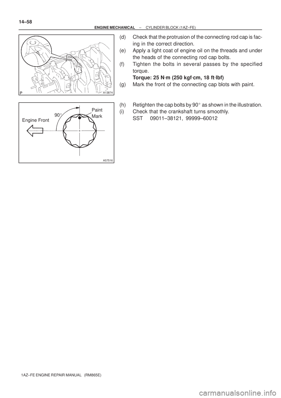
A13874
90�
A57516
Engine FrontPaint
Mark 14±58
± ENGINE MECHANICALCYLINDER BLOCK (1AZ±FE)
1AZ±FE ENGINE REPAIR MANUAL (RM865E)
(d) Check that the protrusion of the connecting rod cap is fac-
ing in the correct direction.
(e) Apply a light coat of engine oil on the threads and under
the heads of the connecting rod cap bolts.
(f) Tighten the bolts in several passes by the specified
torque.
Torque: 25 N�m (250 kgf�cm, 18 ft�lbf)
(g) Mark the front of the connecting cap blots with paint.
(h) Retighten the cap bolts by 90� as shown in the illustration.
(i) Check that the crankshaft turns smoothly.
SST 09011±38121, 99999±60012
Page 3727 of 5135
140DV±01
SST
A57488Wooden Blocks
SST
A57489Wooden Blocks
A13356
14±30
± ENGINE MECHANICALCYLINDER HEAD ASSY (1AZ±FE)
1AZ±FE ENGINE REPAIR MANUAL (RM865E)
CYLINDER HEAD ASSY (1AZ±FE)
OVERHAUL
1. REMOVE VALVE LIFTER
HINT:
Arrange the valve lifters in the correct order.
2. REMOVE INTAKE VALVE
(a) Using SST and wooden blocks, compress and remove
the 8 valve spring retainer locks.
SST 09202±70020 (09202±00010)
(b) Remove the parts below from the cylinder head.
1Retainer
2Valve spring
3Intake valve
HINT:
Arrange the removed parts in the correct order.
3. REMOVE EXHAUST VALVE
(a) UsIng SST and wooden blocks, compress and remove
the 8 valve spring retainer locks.
SST 09202±70020 (09202±00010)
(b) Remove the parts below from the cylinder head.
1Retainer
2Valve spring
3Exhaust valve
4. REMOVE VALVE STEM OIL O SEAL OR RING
(a) Using needle±nose pliers, remove the oil seals.
5. REMOVE VALVE SPRING SEAT
6. REMOVE STUD BOLT
 Upward
Painted Mark
No. 2
A57515
Front
Side Rail UpperSide Rail Lower
Expander
Compression No. 1 and
± ENGINE MECHANICALCYL")

1AZ±FE ENGINE REPAIR MANUAL (RM865E)
CYLINDER HEAD ASSY (1AZ±FE)
OVERHAUL
1")