Page 3741 of 5135
C68518
C83566
C83565
C83567
41±80
± MANUAL TRANSMISSION/TRANSAXLEDIFFERENTIAL CASE ASSY (E355/E356)
E355,E356 M/T REPAIR MANUAL (RM867E)
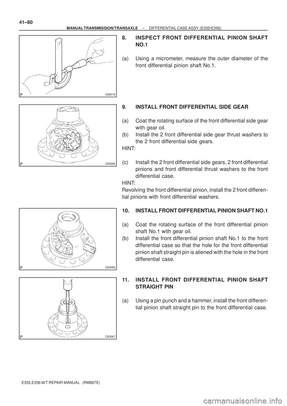
8. INSPECT FRONT DIFFERENTIAL PINION SHAFT
NO.1
(a) Using a micrometer, measure the outer diameter of the
front differential pinion shaft No.1.
9. INSTALL FRONT DIFFERENTIAL SIDE GEAR
(a) Coat the rotating surface of the front differential side gear
with gear oil.
(b) Install the 2 front differential side gear thrust washers to
the 2 front differential side gears.
HINT:
(c) Install the 2 front differential side gears, 2 front differential
pinions and front differential thrust washers to the front
differential case.
HINT:
Revolving the front differential pinion, install the 2 front differen-
tial pinions with front differential washers.
10. INSTALL FRONT DIFFERENTIAL PINION SHAFT NO.1
(a) Coat the rotating surface of the front differential pinion
shaft No.1 with gear oil.
(b) Install the front differential pinion shaft No.1 to the front
differential case so that the hole for the front differential
pinion shaft straight pin is aliened with the hole in the front
differential case.
11. INSTALL FRONT DIFFERENTIAL PINION SHAFT
STRAIGHT PIN
(a) Using a pin punch and a hammer, install the front differen-
tial pinion shaft straight pin to the front differential case.
Page 3744 of 5135
C69531
C69798
C69534
C69535
± MANUAL TRANSMISSION/TRANSAXLESHIFT & SELECT LEVER SHAFT ASSY (E355/E356)
41±73
E355,E356 M/T REPAIR MANUAL (RM867E)
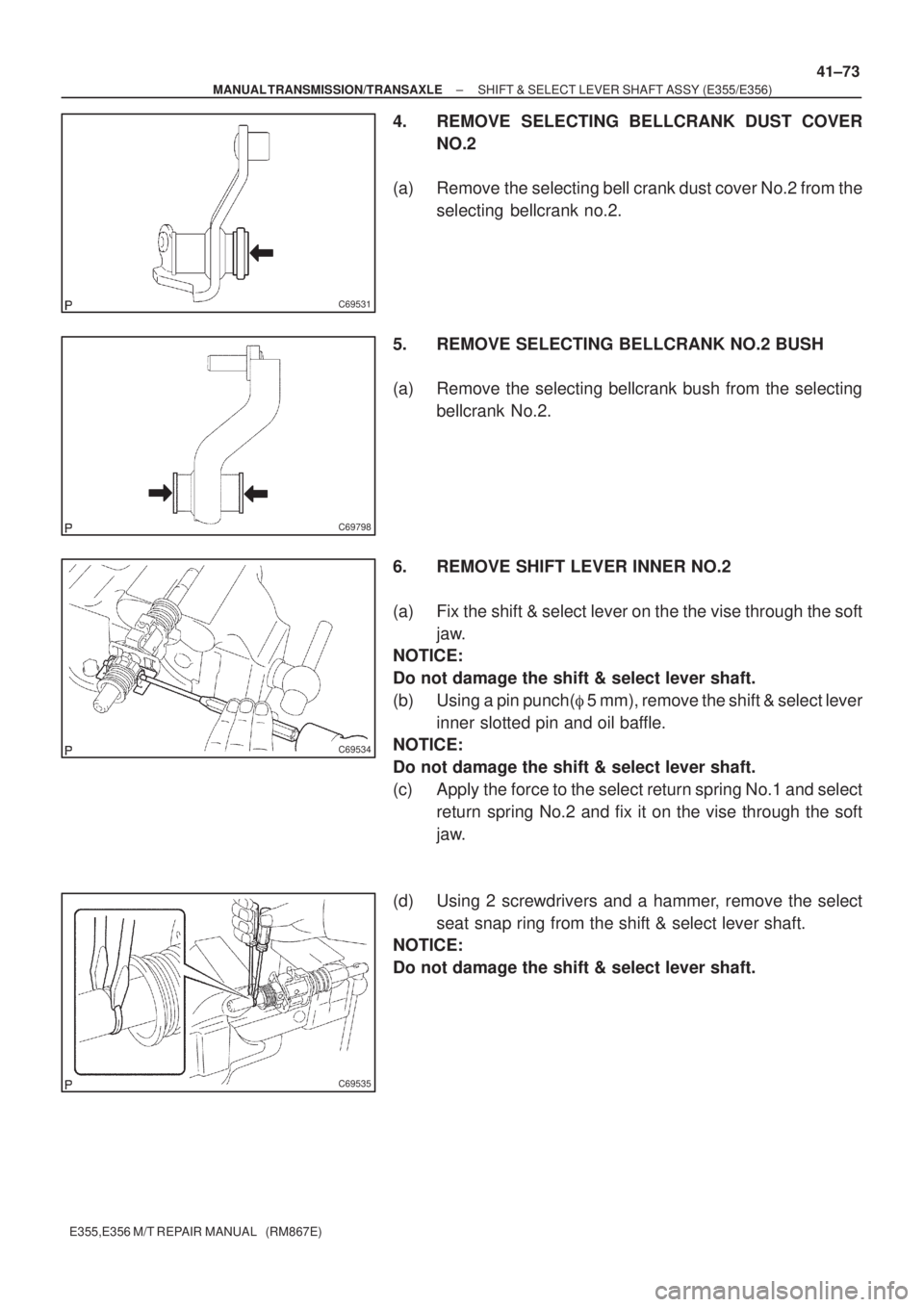
4. REMOVE SELECTING BELLCRANK DUST COVER
NO.2
(a) Remove the selecting bell crank dust cover No.2 from the
selecting bellcrank no.2.
5. REMOVE SELECTING BELLCRANK NO.2 BUSH
(a) Remove the selecting bellcrank bush from the selecting
bellcrank No.2.
6. REMOVE SHIFT LEVER INNER NO.2
(a) Fix the shift & select lever on the the vise through the soft
jaw.
NOTICE:
Do not damage the shift & select lever shaft.
(b) Using a pin punch(� 5 mm), remove the shift & select lever
inner slotted pin and oil baffle.
NOTICE:
Do not damage the shift & select lever shaft.
(c) Apply the force to the select return spring No.1 and select
return spring No.2 and fix it on the vise through the soft
jaw.
(d) Using 2 screwdrivers and a hammer, remove the select
seat snap ring from the shift & select lever shaft.
NOTICE:
Do not damage the shift & select lever shaft.
Page 3747 of 5135
C69536
C69536
C69542
C69798
C69531
41±76
± MANUAL TRANSMISSION/TRANSAXLESHIFT & SELECT LEVER SHAFT ASSY (E355/E356)
E355,E356 M/T REPAIR MANUAL (RM867E)
15. INSTALL SHIFT LEVER INNER NO.2
(a) shift lever inner No.2, select return spring No.2 and select
return spring seat No.2 to the shift & select lever shaft.
(b) Using a brass bar and a hammer, install the select seat
snap ring to the shift & select lever shaft.
(c) Install the transmission oil baffle. Using a pin punch(� 5
mm) and a hammer, install the shift inner lever slotted pin
to the shift & select lever shaft.
Clearance:5.8 ± 6.8mm (0.2303 ± 0.2700 in.)
16. INSTALL SELECTING BELLCRANK NO.2 BUSH
(a) Coat the 2 selecting bellcrank No.2 bushes with MP
grease, install it to the selecting bellcrank No.2.
17. INSTALL SELECTING BELLCRANK DUST COVER
NO.2
(a) Coat the selecting bellcrank dust cover No.2 with MP
grease, install it to the selecting bellcrank No.2.
Page 3754 of 5135
C69657
C69656
C69658
C69659
41±66
± MANUAL TRANSMISSION/TRANSAXLEOUTPUT SHAFT ASSY (E355/E356)
E355,E356 M/T REPAIR MANUAL (RM867E)
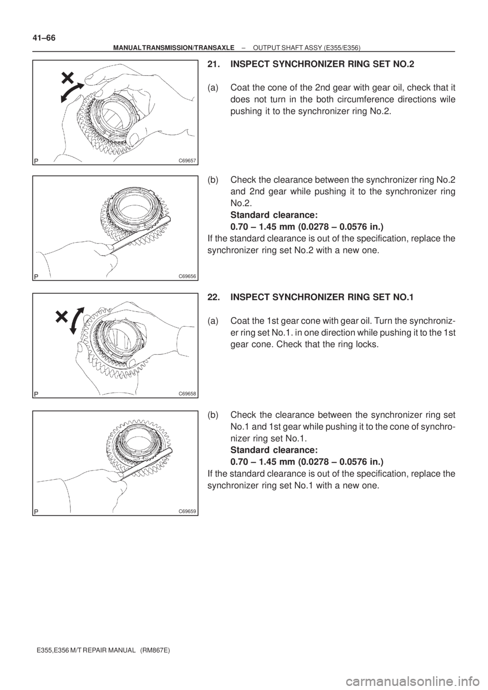
21. INSPECT SYNCHRONIZER RING SET NO.2
(a) Coat the cone of the 2nd gear with gear oil, check that it
does not turn in the both circumference directions wile
pushing it to the synchronizer ring No.2.
(b) Check the clearance between the synchronizer ring No.2
and 2nd gear while pushing it to the synchronizer ring
No.2.
Standard clearance:
0.70 ± 1.45 mm (0.0278 ± 0.0576 in.)
If the standard clearance is out of the specification, replace the
synchronizer ring set No.2 with a new one.
22. INSPECT SYNCHRONIZER RING SET NO.1
(a) Coat the 1st gear cone with gear oil. Turn the synchroniz-
er ring set No.1. in one direction while pushing it to the 1st
gear cone. Check that the ring locks.
(b) Check the clearance between the synchronizer ring set
No.1 and 1st gear while pushing it to the cone of synchro-
nizer ring set No.1.
Standard clearance:
0.70 ± 1.45 mm (0.0278 ± 0.0576 in.)
If the standard clearance is out of the specification, replace the
synchronizer ring set No.1 with a new one.
Page 3755 of 5135
C70507
C69671
C69672
SST
C69674
± MANUAL TRANSMISSION/TRANSAXLEOUTPUT SHAFT ASSY (E355/E356)
41±67
E355,E356 M/T REPAIR MANUAL (RM867E)
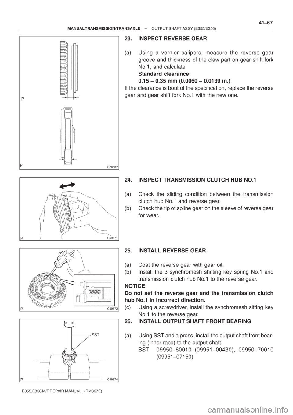
23. INSPECT REVERSE GEAR
(a) Using a vernier calipers, measure the reverse gear
groove and thickness of the claw part on gear shift fork
No.1, and calculate
Standard clearance:
0.15 ± 0.35 mm (0.0060 ± 0.0139 in.)
If the clearance is bout of the specification, replace the reverse
gear and gear shift fork No.1 with the new one.
24. INSPECT TRANSMISSION CLUTCH HUB NO.1
(a) Check the sliding condition between the transmission
clutch hub No.1 and reverse gear.
(b) Check the tip of spline gear on the sleeve of reverse gear
for wear.
25. INSTALL REVERSE GEAR
(a) Coat the reverse gear with gear oil.
(b) Install the 3 synchromesh shifting key spring No.1 and
transmission clutch hub No.1 to the reverse gear.
NOTICE:
Do not set the reverse gear and the transmission clutch
hub No.1 in incorrect direction.
(c) Using a screwdriver, install the synchromesh sifting key
No.1 to the reverse gear.
26. INSTALL OUTPUT SHAFT FRONT BEARING
(a) Using SST and a press, install the output shaft front bear-
ing (inner race) to the output shaft.
SST 09950±60010 (09951±00430), 09950±70010
(09951±07150)
Page 3756 of 5135
C69649
C69650
C69673
SST
SST
C69675
C83814
41±68
± MANUAL TRANSMISSION/TRANSAXLEOUTPUT SHAFT ASSY (E355/E356)
E355,E356 M/T REPAIR MANUAL (RM867E)
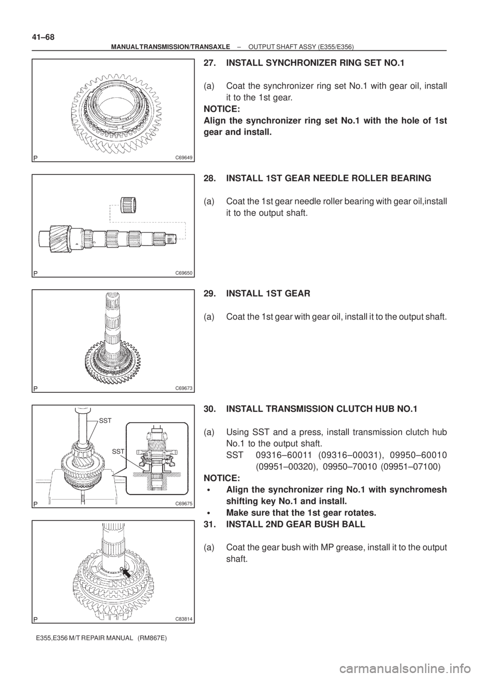
27. INSTALL SYNCHRONIZER RING SET NO.1
(a) Coat the synchronizer ring set No.1 with gear oil, install
it to the 1st gear.
NOTICE:
Align the synchronizer ring set No.1 with the hole of 1st
gear and install.
28. INSTALL 1ST GEAR NEEDLE ROLLER BEARING
(a) Coat the 1st gear needle roller bearing with gear oil,install
it to the output shaft.
29. INSTALL 1ST GEAR
(a) Coat the 1st gear with gear oil, install it to the output shaft.
30. INSTALL TRANSMISSION CLUTCH HUB NO.1
(a) Using SST and a press, install transmission clutch hub
No.1 to the output shaft.
SST 09316±60011 (09316±00031), 09950±60010
(09951±00320), 09950±70010 (09951±07100)
NOTICE:
�Align the synchronizer ring No.1 with synchromesh
shifting key No.1 and install.
�Make sure that the 1st gear rotates.
31. INSTALL 2ND GEAR BUSH BALL
(a) Coat the gear bush with MP grease, install it to the output
shaft.
Page 3757 of 5135
C69646
C69645
C69644
C69643
C69679
± MANUAL TRANSMISSION/TRANSAXLEOUTPUT SHAFT ASSY (E355/E356)
41±69
E355,E356 M/T REPAIR MANUAL (RM867E)
32. INSTALL 2ND GEAR BUSH
(a) Coat the gear 2nd gear bush with gear oil, install it to the
output shaft.
33. INSTALL 2ND GEAR BEARING SPACER
(a) Coat the gear 2nd gear bearing spacer with gear oil,
install it to the output shaft.
34. INSTALL 2ND GEAR NEEDLE ROLLER BEARING
(a) Coat the 2nd gear needle roller bearing with gear oil,
install it to the output shaft.
35. INSTALL SYNCHRONIZER RING SET NO.2
(a) Coat the synchronizer ring set No.2 with gear oil, install
it to the transmission clutch hub No.1
NOTICE:
Align the key groove on the synchronizer ring set No.2 with
the synchromesh shifting key No.1.
36. INSTALL 2ND GEAR
(a) Coat the 2nd gear with gear oil, install it to the output
shaft.
Page 3764 of 5135
ABC
C83823
C69622
C69622
C69623
41±54
± MANUAL TRANSMISSION/TRANSAXLEINPUT SHAFT ASSY (E355/E356)
E355,E356 M/T REPAIR MANUAL (RM867E)
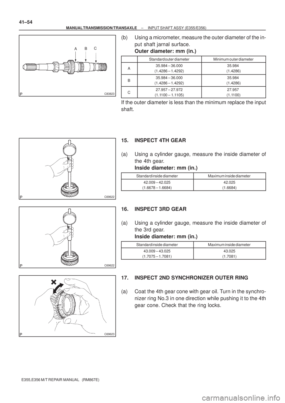
(b) Using a micrometer, measure the outer diameter of the in-
put shaft jarnal surface.
Outer diameter: mm (in.)
Standard outer diameterMinimum outer diameter
A35.984 ± 36.000
(1.4286 ± 1.4292)35.984
(1.4286)
B35.984 ± 36.000
(1.4286 ± 1.4292)35.984
(1.4286)
C27.957 ± 27.972
(1.1100 ± 1.1105)27.957
(1.1100)
If the outer diameter is less than the minimum replace the input
shaft.
15. INSPECT 4TH GEAR
(a) Using a cylinder gauge, measure the inside diameter of
the 4th gear.
Inside diameter: mm (in.)
Standard inside diameterMaximum inside diameter
42.009 ± 42.025
(1.6678 ± 1.6684)42.025
(1.6684)
16. INSPECT 3RD GEAR
(a) Using a cylinder gauge, measure the inside diameter of
the 3rd gear.
Inside diameter: mm (in.)
Standard inside diameterMaximum inside diameter
43.009 ± 43.025
(1.7075 ± 1.7081)43.025
(1.7081)
17. INSPECT 2ND SYNCHRONIZER OUTER RING
(a) Coat the 4th gear cone with gear oil. Turn in the synchro-
nizer ring No.3 in one direction while pushing it to the 4th
gear cone. Check that the ring locks.