Page 3765 of 5135
C69624
C69625
C69626
C67843
± MANUAL TRANSMISSION/TRANSAXLEINPUT SHAFT ASSY (E355/E356)
41±55
E355,E356 M/T REPAIR MANUAL (RM867E)
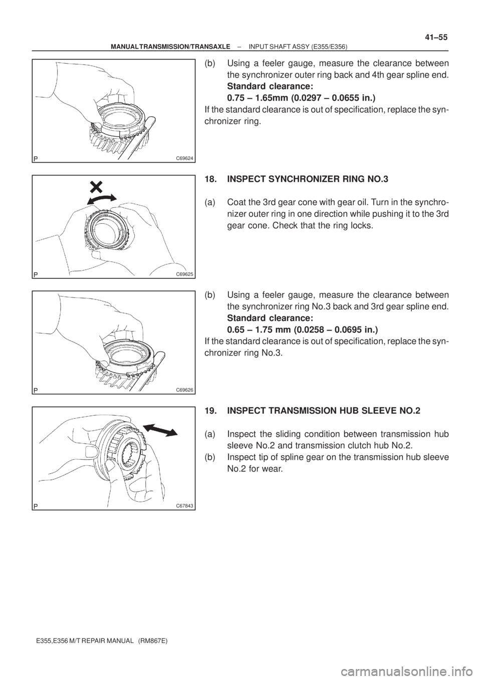
(b) Using a feeler gauge, measure the clearance between
the synchronizer outer ring back and 4th gear spline end.
Standard clearance:
0.75 ± 1.65mm (0.0297 ± 0.0655 in.)
If the standard clearance is out of specification, replace the syn-
chronizer ring.
18. INSPECT SYNCHRONIZER RING NO.3
(a) Coat the 3rd gear cone with gear oil. Turn in the synchro-
nizer outer ring in one direction while pushing it to the 3rd
gear cone. Check that the ring locks.
(b) Using a feeler gauge, measure the clearance between
the synchronizer ring No.3 back and 3rd gear spline end.
Standard clearance:
0.65 ± 1.75 mm (0.0258 ± 0.0695 in.)
If the standard clearance is out of specification, replace the syn-
chronizer ring No.3.
19. INSPECT TRANSMISSION HUB SLEEVE NO.2
(a) Inspect the sliding condition between transmission hub
sleeve No.2 and transmission clutch hub No.2.
(b) Inspect tip of spline gear on the transmission hub sleeve
No.2 for wear.
Page 3766 of 5135
C70506
SST
C69767
C69660
C69617
41±56
± MANUAL TRANSMISSION/TRANSAXLEINPUT SHAFT ASSY (E355/E356)
E355,E356 M/T REPAIR MANUAL (RM867E)
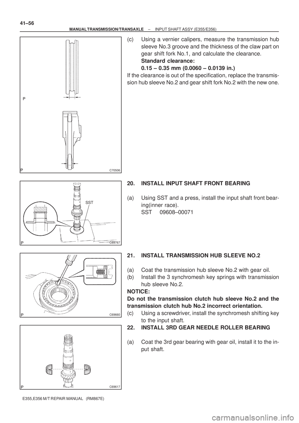
(c) Using a vernier calipers, measure the transmission hub
sleeve No.3 groove and the thickness of the claw part on
gear shift fork No.1, and calculate the clearance.
Standard clearance:
0.15 ± 0.35 mm (0.0060 ± 0.0139 in.)
If the clearance is out of the specification, replace the transmis-
sion hub sleeve No.2 and gear shift fork No.2 with the new one.
20. INSTALL INPUT SHAFT FRONT BEARING
(a) Using SST and a press, install the input shaft front bear-
ing(inner race).
SST 09608±00071
21. INSTALL TRANSMISSION HUB SLEEVE NO.2
(a) Coat the transmission hub sleeve No.2 with gear oil.
(b) Install the 3 synchromesh key springs with transmission
hub sleeve No.2.
NOTICE:
Do not the transmission clutch hub sleeve No.2 and the
transmission clutch hub No.2 incorrect orientation.
(c) Using a screwdriver, install the synchromesh shifting key
to the input shaft.
22. INSTALL 3RD GEAR NEEDLE ROLLER BEARING
(a) Coat the 3rd gear bearing with gear oil, install it to the in-
put shaft.
Page 3767 of 5135
C69629
C69630
SST
C69631
C69632
± MANUAL TRANSMISSION/TRANSAXLEINPUT SHAFT ASSY (E355/E356)
41±57
E355,E356 M/T REPAIR MANUAL (RM867E)
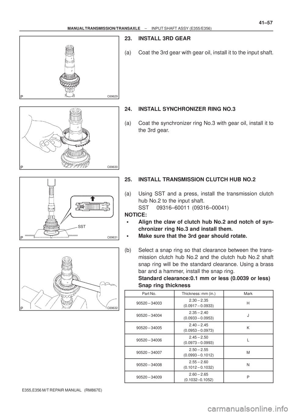
23. INSTALL 3RD GEAR
(a) Coat the 3rd gear with gear oil, install it to the input shaft.
24. INSTALL SYNCHRONIZER RING NO.3
(a) Coat the synchronizer ring No.3 with gear oil, install it to
the 3rd gear.
25. INSTALL TRANSMISSION CLUTCH HUB NO.2
(a) Using SST and a press, install the transmission clutch
hub No.2 to the input shaft.
SST 09316±60011 (09316±00041)
NOTICE:
�Align the claw of clutch hub No.2 and notch of syn-
chronizer ring No.3 and install them.
�Make sure that the 3rd gear should rotate.
(b) Select a snap ring so that clearance between the trans-
mission clutch hub No.2 and the clutch hub No.2 shaft
snap ring will be the standard clearance. Using a brass
bar and a hammer, install the snap ring.
Standard clearance:0.1 mm or less (0.0039 or less)
Snap ring thickness
Part No.Thickness: mm (in.)Mark
90520 ± 340032.30 ± 2.35
(0.0917 ± 0.0933)H
90520 ± 340042.35 ± 2.40
(0.0933 ± 0.0953)J
90520 ± 340052.40 ± 2.45
(0.0953 ± 0.0973)K
90520 ± 340062.45 ± 2.50
(0.0973 ± 0.0993)L
90520 ± 340072.50 ± 2.55
(0.0993 ± 0.1012)M
90520 ± 340082.55 ± 2.60
(0.1012 ± 0.1032)N
90520 ± 340092.60 ± 2.65
(0.1032 ±0.1052)P
Page 3768 of 5135
C69553
C69552
C69551
C69633
SST
C69634
41±58
± MANUAL TRANSMISSION/TRANSAXLEINPUT SHAFT ASSY (E355/E356)
E355,E356 M/T REPAIR MANUAL (RM867E)
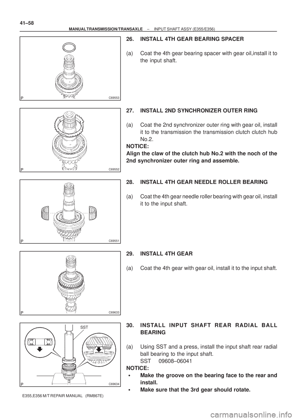
26. INSTALL 4TH GEAR BEARING SPACER
(a) Coat the 4th gear bearing spacer with gear oil,install it to
the input shaft.
27. INSTALL 2ND SYNCHRONIZER OUTER RING
(a) Coat the 2nd synchronizer outer ring with gear oil, install
it to the transmission the transmission clutch clutch hub
No.2.
NOTICE:
Align the claw of the clutch hub No.2 with the noch of the
2nd synchronizer outer ring and assemble.
28. INSTALL 4TH GEAR NEEDLE ROLLER BEARING
(a) Coat the 4th gear needle roller bearing with gear oil, install
it to the input shaft.
29. INSTALL 4TH GEAR
(a) Coat the 4th gear with gear oil, install it to the input shaft.
30. INSTALL INPUT SHAFT REAR RADIAL BALL
BEARING
(a) Using SST and a press, install the input shaft rear radial
ball bearing to the input shaft.
SST 09608±06041
NOTICE:
�Make the groove on the bearing face to the rear and
install.
�Make sure that the 3rd gear should rotate.
Page 3771 of 5135
140KN±01
A62780
SST
A62781
SST
14±28
± ENGINE MECHANICALCYLINDER HEAD ASSY (1ZZ±FE/3ZZ±FE)
1ZZ±FE,3ZZ±FE ENGINE REPAIR MANUAL
(RM923E)
OVERHAUL
1. REMOVE W/HEAD TAPER SCREW PLUG NO.2
(a) Using a socket hexagon wench 10, remove the taper screw plug and gasket.
2. REMOVE VALVE LIFTER
(a) Remove the 16 valve lifters from the cylinder head.
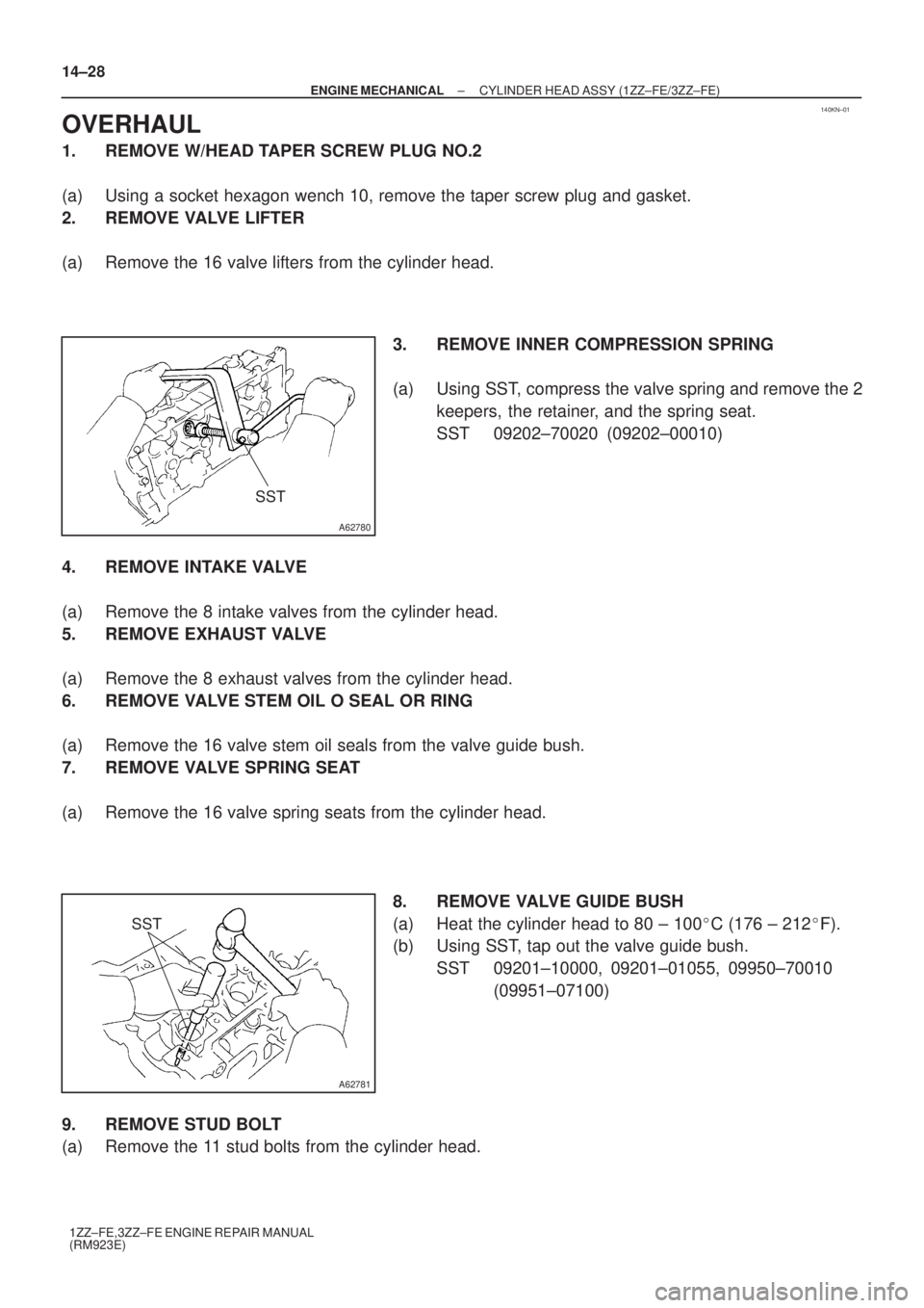
3. REMOVE INNER COMPRESSION SPRING
(a) Using SST, compress the valve spring and remove the 2
keepers, the retainer, and the spring seat.
SST 09202±70020 (09202±00010)
4. REMOVE INTAKE VALVE
(a) Remove the 8 intake valves from the cylinder head.
5. REMOVE EXHAUST VALVE
(a) Remove the 8 exhaust valves from the cylinder head.
6. REMOVE VALVE STEM OIL O SEAL OR RING
(a) Remove the 16 valve stem oil seals from the valve guide bush.
7. REMOVE VALVE SPRING SEAT
(a) Remove the 16 valve spring seats from the cylinder head.
8. REMOVE VALVE GUIDE BUSH
(a) Heat the cylinder head to 80 ± 100�C (176 ± 212�F).
(b) Using SST, tap out the valve guide bush.
SST 09201±10000, 09201±01055, 09950±70010
(09951±07100)
9. REMOVE STUD BOLT
(a) Remove the 11 stud bolts from the cylinder head.
Page 3772 of 5135
A01075
A01071
A62782
A62783
± ENGINE MECHANICALCYLINDER HEAD ASSY (1ZZ±FE/3ZZ±FE)
14±29
1ZZ±FE,3ZZ±FE ENGINE REPAIR MANUAL
(RM923E)
10. INSPECT CYLINDER HEAD FOR FLATNESS
(a) Using a precision straight edge and a feeler gauge, mea-
sure the surface contacting the cylinder block and the
manifolds for warpage.
Maximum warpage:
Cylinder block side0.05 mm (0.0020 in.)
Intake manifold side0.10 mm (0.0040 in.)
Exhaust manifold side0.10 mm (0.0040 in.)
11. INSPECT CYLINDER HEAD FOR CRACKS
(a) Using a dye penetrate, check the combustion chamber,
intake ports, exhaust ports and cylinder block surface for
cracks.
12. INSPECT VALVE GUIDE BUSHING OIL CLEARANCE
(a) Using a caliper gauge, measure the inside diameter of the
valve guide bush.
Busing inside diameter:
5.510 ± 5.530 mm (0.2169 ± 0.2177 in.)
(b) Using a micrometer, measure the diameter of the valve
stem.
Valve stem diameter:
Intake 5.470 ± 5.485 mm (0.2154 ± 0.2159 in.)
Exhaust 5.465 ± 5.480 mm (0.2152 ± 0.2158 in.)
Page 3773 of 5135
A01445
EM0801
A62784
Deviation 14±30
± ENGINE MECHANICALCYLINDER HEAD ASSY (1ZZ±FE/3ZZ±FE)
1ZZ±FE,3ZZ±FE ENGINE REPAIR MANUAL
(RM923E)
(c) Subtract the valve stem diameter measurement from the
guide bushing inside diameter measurement.
Standard oil clearance:
Intake 0.025 ± 0.060 mm (0.0010 ± 0.0024 in.)
Exhaust 0.030 ± 0.065 mm (0.0012 ± 0.0026 in.)
Maximum oil clearance:
Intake 0.08 mm (0.0031 in.)
Exhaust 0.01 mm (0.0039 in.)
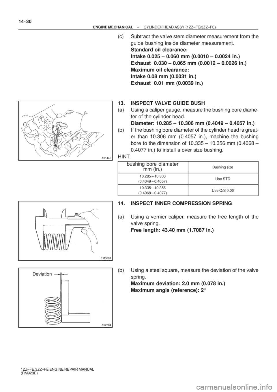
13. INSPECT VALVE GUIDE BUSH
(a) Using a caliper gauge, measure the bushing bore diame-
ter of the cylinder head.
Diameter: 10.285 ± 10.306 mm (0.4049 ± 0.4057 in.)
(b) If the bushing bore diameter of the cylinder head is great-
er than 10.306 mm (0.4057 in.), machine the bushing
bore to the dimension of 10.335 ± 10.356 mm (0.4068 ±
0.4077 in.) to install a over size bushing.
HINT:
bushing bore diameter
mm (in.)
Bushing size
10.285 ± 10.306
(0.4049 ± 0.4057)Use STD
10.335 ± 10.356
(0.4068 ± 0.4077)Use O/S 0.05
14. INSPECT INNER COMPRESSION SPRING
(a) Using a vernier caliper, measure the free length of the
valve spring.
Free length: 43.40 mm (1.7087 in.)
(b) Using a steel square, measure the deviation of the valve
spring.
Maximum deviation: 2.0 mm (0.078 in.)
Maximum angle (reference): 2�
Page 3775 of 5135
A62787
1.0 ± 1.4 mm30� 45�
A62788
1.0 ± 1.4 mm60�
45�
P16860
A01080
14±32
± ENGINE MECHANICALCYLINDER HEAD ASSY (1ZZ±FE/3ZZ±FE)
1ZZ±FE,3ZZ±FE ENGINE REPAIR MANUAL
(RM923E)
(2) If blue appears 360� around the valve seat, the
guide and face are concentric. If not, resurface the
seat.
(3) Check that the seat contact is in the middle of the
valve face with the width between 1.0 ± 1.4 mm
(0.039 ± 0.055 in.).
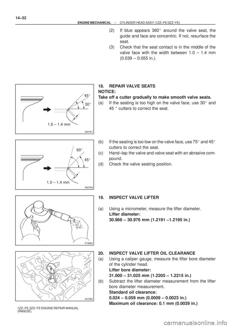
18. REPAIR VALVE SEATS
NOTICE:
Take off a cutter gradually to make smooth valve seats.
(a) If the seating is too high on the valve face, use 30� and
45 � cutters to correct the seat.
(b) If the seating is too low on the valve face, use 75� and 45�
cutters to correct the seat.
(c) Hand±lap the valve and valve seat with an abrasive com-
pound.
(d) Check the valve seating position.
19. INSPECT VALVE LIFTER
(a) Using a micrometer, measure the lifter diameter.
Lifter diameter:
30.966 ± 30.976 mm (1.2191 ±1.2195 in.)
20. INSPECT VALVE LIFTER OIL CLEARANCE
(a) Using a caliper gauge, measure the lifter bore diameter
of the cylinder head.
Lifter bore diameter:
31.000 ± 31.025 mm (1.2205 ± 1.2215 in.)
(b) Subtract the lifter diameter measurement from the lifter
bore diameter measurement.
Standard oil clearance:
0.024 ± 0.059 mm (0.0009 ± 0.0023 in.)
Maximum oil clearance: 0.1 mm (0.0039 in.)