Page 3689 of 5135
C83143
C83142
D08034
D08093
± AUTOMATIC TRANSMISSION / TRANSAUTOMATIC TRANSAXLE ASSY (U241E)
40±67
U241E A/T REPAIR MANUAL (RM840U)
141. INSTALL OIL COOLER TUBE UNION
(a) Coat a new O±ring with ATF, install it to the union.
(b) Install the union to the transaxle case.
Torque: 27 N�m (280 kgf�cm, 20 ft�lbf)
142. INSTALL TRANSAXLE CASE NO.1 PLUG
(a) Coat 4 new O±rings with ATF, install them to the 4 trans-
axle case No. 1 plugs.
(b) Install the 4 transaxle case No. 1 plugs to the transaxle
case.
Torque: 7.4 N�m (75 kgf�cm, 65 in.�lbf)
143. INSTALL BREATHER PLUG HOSE
(a) Install the breather plug hose to the breather No. 2 plug.
144. INSTALL PARK/NEUTRAL POSITION SWITCH ASSY
(a) Install the park/neutral position switch onto the manual
valve lever shaft and temporarily install the 2 adjusting
bolts.
(b) Install a new nut stopper and nut.
Torque: 6.9 N�m (70 kgf�cm, 61 in.�lbf)
(c) Temporarily install control shaft lever.
Page 3703 of 5135
C83135
C83136
D25600
SST
D25599
SST
C83137
40±102
± AUTOMATIC TRANSMISSION / TRANSFRONT DIFFERENTIAL ASSY (U241E)
U241E A/T REPAIR MANUAL (RM840U)
5. REMOVE FRONT DIFFERENTIAL PINION SHAFT
NO.1
(a) Remove the front differential pinion shaft No. 1 from the
differential case.
6. REMOVE FRONT DIFFERENTIAL SIDE GEAR
(a) Remove the 2 front differential pinions, 2 pinion thrust
washers, 2 front differential side gears and 2 side gear
thrust washers from the differential case.
7. REMOVE DIFFERENTIAL SIDE BEARING RETAINER
OIL SEAL
(a) Place the transaxle case in vise.
(b) Using SST, remove the oil seal.
SST 09308±00010
8. REMOVE TRANSAXLE HOUSING OIL SEAL
(a) Place the transaxle housing in vise.
(b) Using SST, remove the oil seal.
SST 09308±00010
9. INSTALL FRONT DIFFERENTIAL SIDE GEAR
(a) Coat the 2 front differential side gears, 2 side gear thrust
washers, 2 front differential pinions and 2 pinion thrust
washers with ATF and install them to the differential case.
Page 3708 of 5135
D25606
SST
D25605
SST
± AUTOMATIC TRANSMISSION / TRANSFRONT DIFFERENTIAL ASSY (U241E)
40±107
U241E A/T REPAIR MANUAL (RM840U)
17. INSTALL TRANSAXLE HOUSING OIL SEAL
(a) Using SST, drive into a new oil seal.
SST 09350±32014 (09351±32150), 09950±70010
(09951±07150)
(b) Coat the rip of oil seal with a little MP grease.
18. INSTALL DIFFERENTIAL SIDE BEARING RETAINER
OIL SEAL
(a) Using SST, drive into a new oil seal.
SST 09350±32014 (09351±32150), 09950±70010
(09951±07150)
(b) Coat the rip of the oil seal with a little MP grease.
Page 3710 of 5135
140DW±01
A13845
A13846
A13848
A13874
14±42
± ENGINE MECHANICALCYLINDER BLOCK (1AZ±FE)
1AZ±FE ENGINE REPAIR MANUAL (RM865E)
CYLINDER BLOCK (1AZ±FE)
OVERHAUL
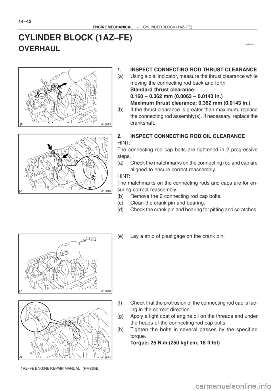
1. INSPECT CONNECTING ROD THRUST CLEARANCE
(a) Using a dial indicator, measure the thrust clearance while
moving the connecting rod back and forth.
Standard thrust clearance:
0.160 ± 0.362 mm (0.0063 ± 0.0143 in.)
Maximum thrust clearance: 0.362 mm (0.0143 in.)
(b) If the thrust clearance is greater than maximum, replace
the connecting rod assembly(s). If necessary, replace the
crankshaft.
2. INSPECT CONNECTING ROD OIL CLEARANCE
HINT:
The connecting rod cap bolts are tightened in 2 progressive
steps.
(a) Check the matchmarks on the connecting rod and cap are
aligned to ensure correct reassembly.
HINT:
The matchmarks on the connecting rods and caps are for en-
suring correct reassembly.
(b) Remove the 2 connecting rod cap bolts.
(c) Clean the crank pin and bearing.
(d) Check the crank pin and bearing for pitting and scratches.
(e) Lay a strip of plastigage on the crank pin.
(f) Check that the protrusion of the connecting rod cap is fac-
ing in the correct direction.
(g) Apply a light coat of engine oil on the threads and under
the heads of the connecting rod cap bolts.
(h) Tighten the bolts in several passes by the specified
torque.
Torque: 25 N�m (250 kgf�cm, 18 ft�lbf)
Page 3711 of 5135
90�
A57501
Engine FrontPaint
Mark
A13850
A57505
Mark
1, 2 or 3Mark
1, 2 or 3
A13469
± ENGINE MECHANICALCYLINDER BLOCK (1AZ±FE)
14±43
1AZ±FE ENGINE REPAIR MANUAL (RM865E)
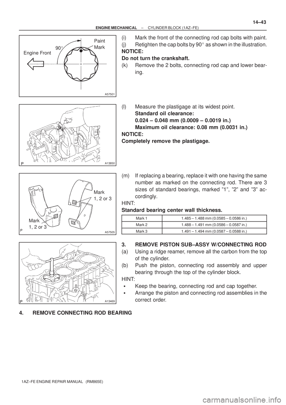
(i) Mark the front of the connecting rod cap bolts with paint.
(j) Retighten the cap bolts by 90� as shown in the illustration.
NOTICE:
Do not turn the crankshaft.
(k) Remove the 2 bolts, connecting rod cap and lower bear-
ing.
(l) Measure the plastigage at its widest point.
Standard oil clearance:
0.024 ± 0.048 mm (0.0009 ± 0.0019 in.)
Maximum oil clearance: 0.08 mm (0.0031 in.)
NOTICE:
Completely remove the plastigage.
(m) If replacing a bearing, replace it with one having the same
number as marked on the connecting rod. There are 3
sizes of standard bearings, marked º1º, º2º and º3º ac-
cordingly.
HINT:
Standard bearing center wall thickness.
Mark 11.485 ± 1.488 mm (0.0585 ± 0.0586 in.)
Mark 21.488 ± 1.491 mm (0.0586 ± 0.0587 in.)
Mark 31.491 ± 1.494 mm (0.0587 ± 0.0588 in.)
3. REMOVE PISTON SUB±ASSY W/CONNECTING ROD
(a) Using a ridge reamer, remove all the carbon from the top
of the cylinder.
(b) Push the piston, connecting rod assembly and upper
bearing through the top of the cylinder block.
HINT:
�Keep the bearing, connecting rod and cap together.
�Arrange the piston and connecting rod assemblies in the
correct order.
4. REMOVE CONNECTING ROD BEARING
Page 3712 of 5135
A36647
A13478
A01178
A01179
A13851
14±44
± ENGINE MECHANICALCYLINDER BLOCK (1AZ±FE)
1AZ±FE ENGINE REPAIR MANUAL (RM865E)
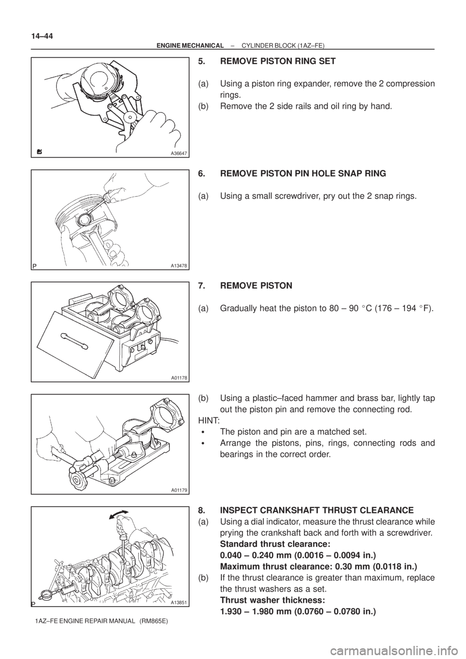
5. REMOVE PISTON RING SET
(a) Using a piston ring expander, remove the 2 compression
rings.
(b) Remove the 2 side rails and oil ring by hand.
6. REMOVE PISTON PIN HOLE SNAP RING
(a) Using a small screwdriver, pry out the 2 snap rings.
7. REMOVE PISTON
(a) Gradually heat the piston to 80 ± 90 �C (176 ± 194 �F).
(b) Using a plastic±faced hammer and brass bar, lightly tap
out the piston pin and remove the connecting rod.
HINT:
�The piston and pin are a matched set.
�Arrange the pistons, pins, rings, connecting rods and
bearings in the correct order.
8. INSPECT CRANKSHAFT THRUST CLEARANCE
(a) Using a dial indicator, measure the thrust clearance while
prying the crankshaft back and forth with a screwdriver.
Standard thrust clearance:
0.040 ± 0.240 mm (0.0016 ± 0.0094 in.)
Maximum thrust clearance: 0.30 mm (0.0118 in.)
(b) If the thrust clearance is greater than maximum, replace
the thrust washers as a set.
Thrust washer thickness:
1.930 ± 1.980 mm (0.0760 ± 0.0780 in.)
Page 3714 of 5135
A
B
10 mm
(0.39 in.)
A57506
Thrust Direction
Axial Direction Front
A56232
30.4 mm
(1.197 in.)
A36650
14±46
± ENGINE MECHANICALCYLINDER BLOCK (1AZ±FE)
1AZ±FE ENGINE REPAIR MANUAL (RM865E)
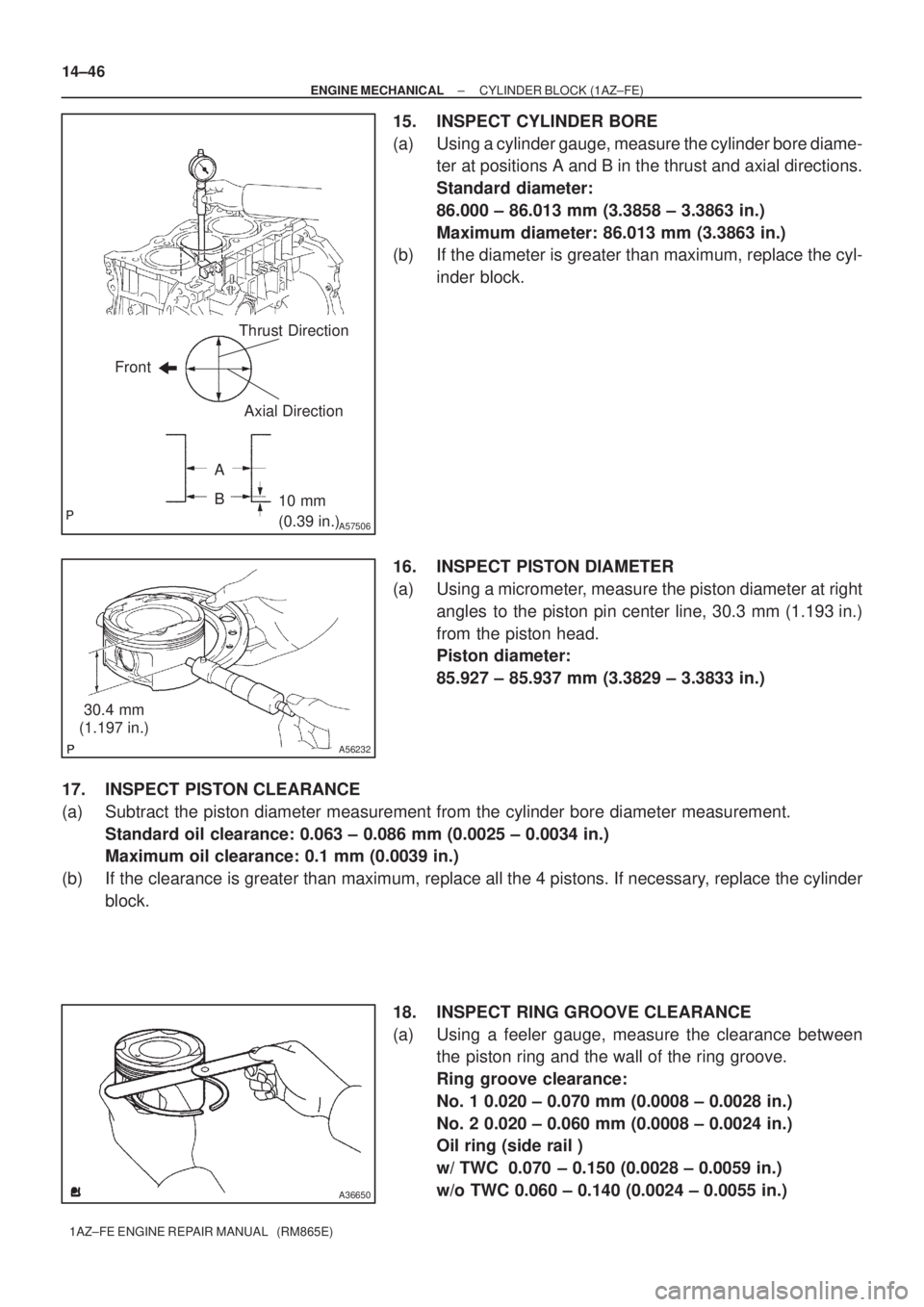
15. INSPECT CYLINDER BORE
(a) Using a cylinder gauge, measure the cylinder bore diame-
ter at positions A and B in the thrust and axial directions.
Standard diameter:
86.000 ± 86.013 mm (3.3858 ± 3.3863 in.)
Maximum diameter: 86.013 mm (3.3863 in.)
(b) If the diameter is greater than maximum, replace the cyl-
inder block.
16. INSPECT PISTON DIAMETER
(a) Using a micrometer, measure the piston diameter at right
angles to the piston pin center line, 30.3 mm (1.193 in.)
from the piston head.
Piston diameter:
85.927 ± 85.937 mm (3.3829 ± 3.3833 in.)
17. INSPECT PISTON CLEARANCE
(a) Subtract the piston diameter measurement from the cylinder bore diameter measurement.
Standard oil clearance: 0.063 ± 0.086 mm (0.0025 ± 0.0034 in.)
Maximum oil clearance: 0.1 mm (0.0039 in.)
(b) If the clearance is greater than maximum, replace all the 4 pistons. If necessary, replace the cylinder
block.
18. INSPECT RING GROOVE CLEARANCE
(a) Using a feeler gauge, measure the clearance between
the piston ring and the wall of the ring groove.
Ring groove clearance:
No. 1 0.020 ± 0.070 mm (0.0008 ± 0.0028 in.)
No. 2 0.020 ± 0.060 mm (0.0008 ± 0.0024 in.)
Oil ring (side rail )
w/ TWC 0.070 ± 0.150 (0.0028 ± 0.0059 in.)
w/o TWC 0.060 ± 0.140 (0.0024 ± 0.0055 in.)
Page 3715 of 5135
11 0 m m
A57507Piston Ring
EM2552
A13490
EM0227
± ENGINE MECHANICALCYLINDER BLOCK (1AZ±FE)
14±47
1AZ±FE ENGINE REPAIR MANUAL (RM865E)
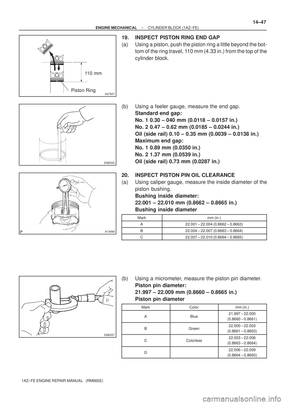
19. INSPECT PISTON RING END GAP
(a) Using a piston, push the piston ring a little beyond the bot-
tom of the ring travel, 110 mm (4.33 in.) from the top of the
cylinder block.
(b) Using a feeler gauge, measure the end gap.
Standard end gap:
No. 1 0.30 ± 040 mm (0.0118 ± 0.0157 in.)
No. 2 0.47 ± 0.62 mm (0.0185 ± 0.0244 in.)
Oil (side rail) 0.10 ± 0.35 mm (0.0039 ± 0.0138 in.)
Maximum end gap:
No. 1 0.89 mm (0.0350 in.)
No. 2 1.37 mm (0.0539 in.)
Oil (side rail) 0.73 mm (0.0287 in.)
20. INSPECT PISTON PIN OIL CLEARANCE
(a) Using caliper gauge, measure the inside diameter of the
piston bushing.
Bushing inside diameter:
22.001 ± 22.010 mm (0.8662 ± 0.8665 in.)
Bushing inside diameter
Markmm (in.)
A22.001 ± 22.004 (0.8662 ± 0.8663)
B22.004 ± 22.007 (0.8663 ± 0.8664)
C22.007 ± 22.010 (0.8664 ± 0.8665)
(b) Using a micrometer, measure the piston pin diameter.
Piston pin diameter:
21.997 ± 22.009 mm (0.8660 ± 0.8665 in.)
Piston pin diameter
MarkColormm (in.)
ABlue21.997 ± 22.000
(0.8660 ± 0.8661)
BGreen22.000 ± 22.003
(0.8661 ± 0.8663)
CColorless22.003 ± 22.006
(0.8663 ± 0.8664)
�22.006 ± 22.009
(0.8664 ± 0.8665)