Page 3562 of 5135
D30539
D30568
SST
D30537
C80396
C80397
Key Position 41±30
± MANUAL TRANSMISSION/TRANSAXLEMANUAL TRANSAXLE ASSY (C250)
C250 M/T REPAIR MANUAL (RM1020E)
88. INSTALL BEARING RETAINER REAR (MTM)
(a) Coat the 5 bolts with sealant, install them and bearing re-
tainer rear to the manual transmission case.
Torque: 27 N�m (280 kgf�cm, 20 ft�lbf)
89. INSTALL 5TH DRIVEN GEAR
(a) Using SST, install the 5th driven gear to the output shaft.
SST 09950±30012 (09951±03010, 09953±03010,
09954±03010, 09955±03011, 09956±03020)
90. INSTALL 5TH GEAR NEEDLE ROLLER BEARING
(a) Coat the 5th gear needle roller bearing and spacer with
gear oil, install them to the input shaft.
91. INSTALL 5TH GEAR
(a) Coat the 5th gear with gear oil, install it to the input shaft.
92. INSTALL SYNCHRONIZER RING NO.3
(a) Coat the synchronizer ring No.3 with gear oil, install it to
the 5th gear.
Page 3564 of 5135

C250 M/T REPAIR MANUAL (RM1020E)
95. INSPECT 5TH GEAR RADIAL CLEARANCE
(a) Using a dial indicat")
C80345
C80401
C80402
C80403
C80404
41±32
± MANUAL TRANSMISSION/TRANSAXLEMANUAL TRANSAXLE ASSY (C250)
C250 M/T REPAIR MANUAL (RM1020E)
95. INSPECT 5TH GEAR RADIAL CLEARANCE
(a) Using a dial indicator, inspect the 5th gear radial clear-
ance.
Standard clearance:
0.015 ± 0.058 mm (0.0006 ± 0.0023 in.)
Maximum clearance:
0.058 mm (0.0023 in.)
If the clearance exceeds the maximum, replace the gear,
needle roller bearing or shaft.
96. INSTALL GEAR SHIFT FORK NO.3
(a) Coat the transmission clutch hub sleeve No.3 with gear
oil, install it and gear shift fork No.3 to the transmission
clutch hub No.3.
HINT:
Do not set the transmission clutch hub No.3 in incorrect orienta-
tion.
(b) Coat the gear shift fork lock bolt with sealant, install it to
the gear shift fork No.3.
Sealant:
Part No. 08833±00080, THREE BOND 1344, LOCTITE
242 or equivalent
Torque: 16 N�m (160 kgf�cm, 12 ft�lbf)
97. INSTALL MANUAL TRANSMISSION OUTPUT SHAFT
REAR SET NUT
(a) Engage the gear double meshing.
(b) Install the new manual transmission output shaft rear set
nut.
Torque: 118 N�m (1200 kgf�cm, 87 ft�lbf)
(c) Using a chisel and hammer, stake the manual transmis-
sion output shaft rear set nut.
(d) Disengage the gear double meshing.
Page 3565 of 5135

41±33
C250 M/T REPAIR MANUAL (RM1020E)
98. INSTALL MANUAL TRANSMISSION CASE COVER
SUB±ASSY
(a)")
C80556
FIPG
C80554
D30534
D30533
D30531
± MANUAL TRANSMISSION/TRANSAXLEMANUAL TRANSAXLE ASSY (C250)
41±33
C250 M/T REPAIR MANUAL (RM1020E)
98. INSTALL MANUAL TRANSMISSION CASE COVER
SUB±ASSY
(a) Apply FIPG to the transaxle case, cover as shown to the
illustration.
FIPG:
Part No. 08826±00090, THREE BOND 1281
NOTICE:
Parts must be assembled within 10 minutes of application.
Otherwise, the packing (FIPG) material must be removed
and reapplied.
(b) Install the 9 bolts with manual transmission case cover to
the manual transmission case.
Torque: 18 N�m (185 kgf�cm, 14 ft�lbf)
99. INSTALL SHIFT & SELECT LEVER SHAFT ASSY
(a) Coat the sift & select lever shaft assy with gear oil, install
it to the manual transmission case.
100. INSTALL CONTROL SHAFT COVER
(a) Coat the 4 bolts with sealant, install the new gasket, con-
trol shaft cover with the bolt.
Sealant:
Part No. 08833±00080, THREE BOND 1344, LOCTITE
242 or equivalent
Torque: 20 N�m (200 kgf�cm, 14 ft�lbf)
101. INSTALL CONTROL SHIFT LEVER
(a) Install the control shift lever with shift outer lever lever lock
pin to the shift & select lever shaft assy.
(b) Install the spring washer with nut.
Torque: 12 N�m (122 kgf�cm, 8.9 ft�lbf)
Page 3577 of 5135

C250 M/T REPAIR MANUAL (RM1020E)
10. REMOVE SELECT SPRING NO.1 SEAT SHAFT SNAP
RING
(a)")
D30556
C80778
C94255
SST
D30557
41±62
± MANUAL TRANSMISSION/TRANSAXLESHIFT & SELECT LEVER SHAFT ASSY (C250)
C250 M/T REPAIR MANUAL (RM1020E)
10. REMOVE SELECT SPRING NO.1 SEAT SHAFT SNAP
RING
(a) Using 2 screwdrivers and a hammer, remove the select
spring No.1 seat shaft snap ring.
NOTICE:
Do not damage the shaft.
11. REMOVE SHIFT & SELECT LEVER SHAFT DUST BOOT
(a) Remove the shift & select lever shaft dust boot from the shift & select lever shaft.
12. REMOVE CONTROL SHAFT COVER OIL SEAL
(a) Using a screwdriver remove the control shaft cover oil
seal from the control shaft cover.
13. INSTALL CONTROL SHAFT COVER OIL SEAL
(a) Using SST and a hammer, install the new control shaft
cover oil seal to the control shaft cover.
SST 09950±60010 (09951±00220), 09950±70010
(09951±07100)
Drive in depth:
0.2 ± 1.2 mm (0.079 ± 0.0472 in.)
(b) Coat the control shaft cover oil seal with MP grease.
14. INSTALL SHIFT & SELECT LEVER SHAFT DUST
BOOT
(a) Coat the shift & select lever shaft dust boot with MP
grease.
(b) Install the shift & select lever shaft dust boot to the shift
& select lever shaft.
HINT:
Install the boot with the projection up and the hole side down.
Page 3580 of 5135
410DI±01
������������
D30695
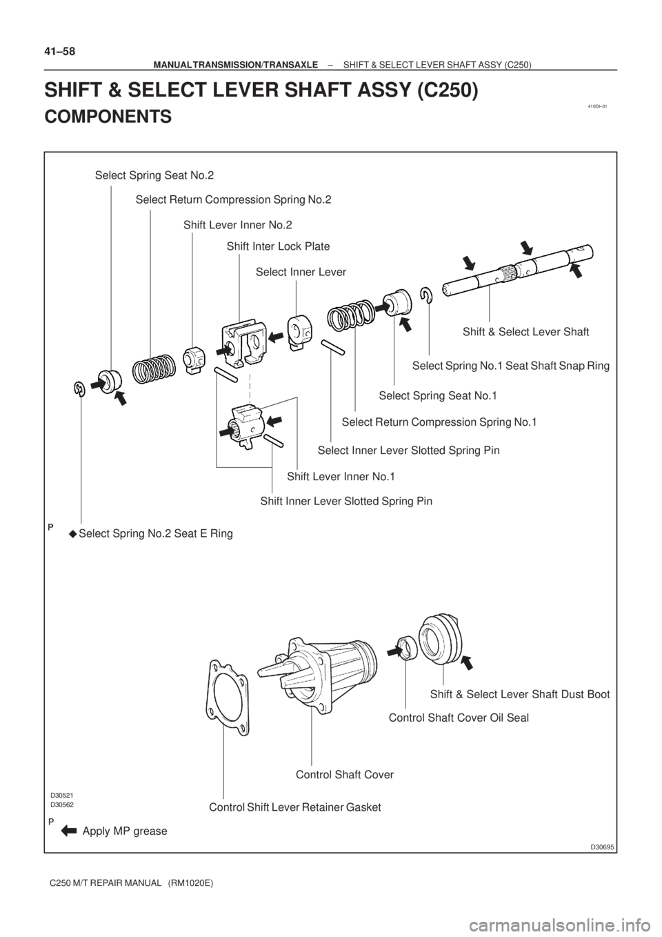
Select Spring Seat No.2
�
Apply MP greaseSelect Spring No.2 Seat E Ring
Shift Lever Inner No.1
Shift Inner Lever Slotted Spring Pin Select Return Compression Spring No.2
Shift Lever Inner No.2
Shift Inter Lock Plate
Select Inner Lever
Select Return Compression Spring No.1
Select Inner Lever Slotted Spring Pin
Select Spring Seat No.1
Select Spring No.1 Seat Shaft Snap Ring
Shift & Select Lever Shaft
Control Shift Lever Retainer Gasket
Control Shaft Cover
Control Shaft Cover Oil SealShift & Select Lever Shaft Dust Boot
41±58
± MANUAL TRANSMISSION/TRANSAXLESHIFT & SELECT LEVER SHAFT ASSY (C250)
C250 M/T REPAIR MANUAL (RM1020E)
SHIFT & SELECT LEVER SHAFT ASSY (C250)
COMPONENTS
Page 3584 of 5135
9808X±01
98±10
± COMPONENTS151350
3514/OIL COOLER & TUBE (ATM)
(0008± )ATM U340E
Page 3586 of 5135
9808V±01
98±8
± COMPONENTS151350
3512/VALVE BODY & OIL STRAINER (ATM)
(0008± )NZE121..ATM U340E
Page 3591 of 5135
9808L±01
± COMPONENTS151350
98±3
3503/TRANSMISSION CASE & OIL PAN (ATM)
(0008± )NZE121..ATM U340E

C250 M/T REPAIR MANUAL (RM1020E)
88. INSTALL BEARING RETAINER REAR (MTM)
(a) C")

(0008± )ATM")

(0008± )NZE121..ATM")

(0008± )NZE121..ATM")