Page 3502 of 5135
A77466
SST
P16860
A13374
± ENGINE MECHANICALCYLINDER HEAD ASSY
14±47
1AZ±FSE ENGINE REPAIR MANUAL (RM1019E)
(b) Install the STD bushing if the diameter is within specified
diameter.
HINT:
STD10.333 to 10.344 mm (0.4068 to 0.4072 in.)
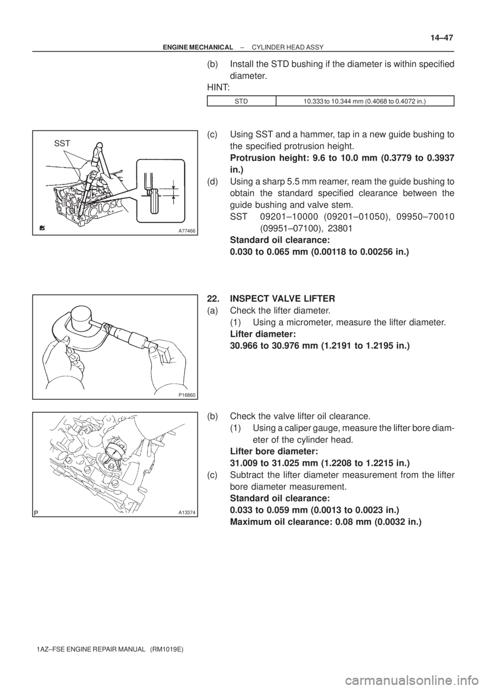
(c) Using SST and a hammer, tap in a new guide bushing to
the specified protrusion height.
Protrusion height: 9.6 to 10.0 mm (0.3779 to 0.3937
in.)
(d) Using a sharp 5.5 mm reamer, ream the guide bushing to
obtain the standard specified clearance between the
guide bushing and valve stem.
SST 09201±10000 (09201±01050), 09950±70010
(09951±07100), 23801
Standard oil clearance:
0.030 to 0.065 mm (0.00118 to 0.00256 in.)
22. INSPECT VALVE LIFTER
(a) Check the lifter diameter.
(1) Using a micrometer, measure the lifter diameter.
Lifter diameter:
30.966 to 30.976 mm (1.2191 to 1.2195 in.)
(b) Check the valve lifter oil clearance.
(1) Using a caliper gauge, measure the lifter bore diam-
eter of the cylinder head.
Lifter bore diameter:
31.009 to 31.025 mm (1.2208 to 1.2215 in.)
(c) Subtract the lifter diameter measurement from the lifter
bore diameter measurement.
Standard oil clearance:
0.033 to 0.059 mm (0.0013 to 0.0023 in.)
Maximum oil clearance: 0.08 mm (0.0032 in.)
Page 3505 of 5135
A77467
Intake Side Exhaust Side
Gray
Black
A77468
SST
A77455
SST
Wooden Blocks
A77469
Vinyl Tape
Valve Stem
A77456
SST
Wooden Blocks 14±50
± ENGINE MECHANICALCYLINDER HEAD ASSY
1AZ±FSE ENGINE REPAIR MANUAL (RM1019E)
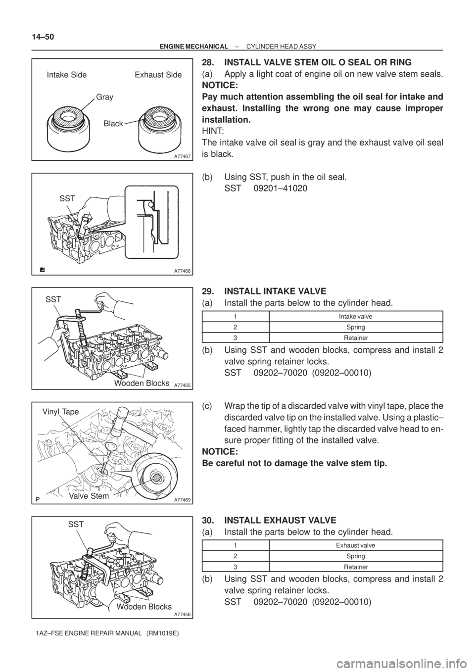
28. INSTALL VALVE STEM OIL O SEAL OR RING
(a) Apply a light coat of engine oil on new valve stem seals.
NOTICE:
Pay much attention assembling the oil seal for intake and
exhaust. Installing the wrong one may cause improper
installation.
HINT:
The intake valve oil seal is gray and the exhaust valve oil seal
is black.
(b) Using SST, push in the oil seal.
SST 09201±41020
29. INSTALL INTAKE VALVE
(a) Install the parts below to the cylinder head.
1Intake valve
2Spring
3Retainer
(b) Using SST and wooden blocks, compress and install 2
valve spring retainer locks.
SST 09202±70020 (09202±00010)
(c) Wrap the tip of a discarded valve with vinyl tape, place the
discarded valve tip on the installed valve. Using a plastic±
faced hammer, lightly tap the discarded valve head to en-
sure proper fitting of the installed valve.
NOTICE:
Be careful not to damage the valve stem tip.
30. INSTALL EXHAUST VALVE
(a) Install the parts below to the cylinder head.
1Exhaust valve
2Spring
3Retainer
(b) Using SST and wooden blocks, compress and install 2
valve spring retainer locks.
SST 09202±70020 (09202±00010)
Page 3506 of 5135
A77469
Vinyl Tape
Valve Stem
± ENGINE MECHANICALCYLINDER HEAD ASSY
14±51
1AZ±FSE ENGINE REPAIR MANUAL (RM1019E)
(c) Wrap the tip of a discarded valve with vinyl tape, place the
discarded valve tip on the installed valve. Using a plastic±
faced hammer, lightly tap the discarded valve head to en-
sure proper fitting of the installed valve.
NOTICE:
Be careful not to damage the valve stem tip.
31. INSTALL VALVE LIFTER
(a) Apply a light coat of engine oil on the valve lifter.
NOTICE:
Install the valve lifters to the original locations.
Page 3519 of 5135
C68017
C68017
C68514
C68023
C68239
41±52
± MANUAL TRANSMISSION/TRANSAXLEOUTPUT SHAFT ASSY (C250)
C250 M/T REPAIR MANUAL (RM1020E)
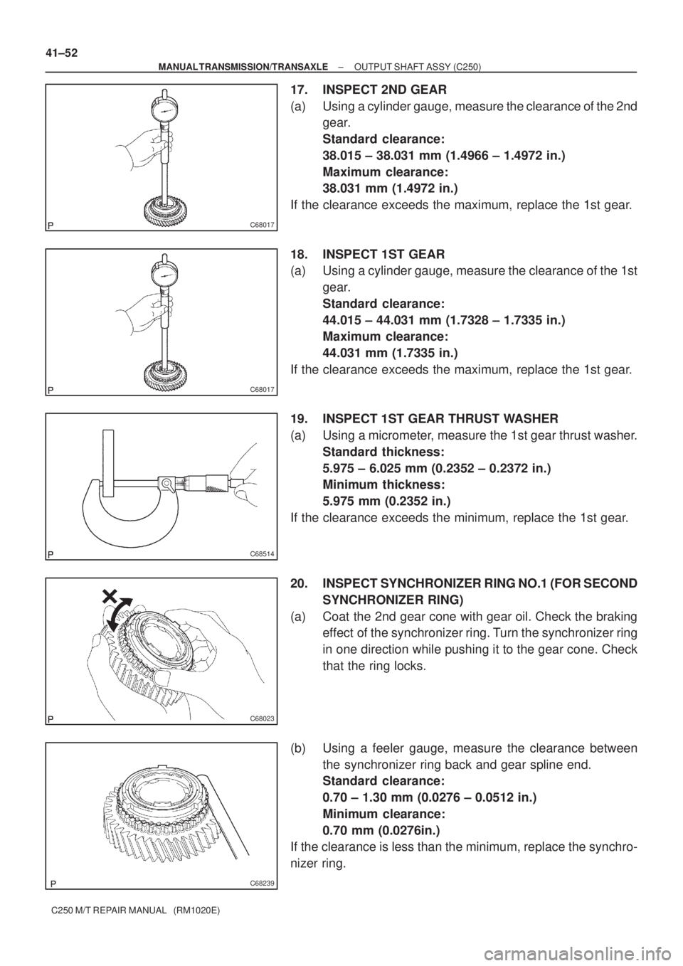
17. INSPECT 2ND GEAR
(a) Using a cylinder gauge, measure the clearance of the 2nd
gear.
Standard clearance:
38.015 ± 38.031 mm (1.4966 ± 1.4972 in.)
Maximum clearance:
38.031 mm (1.4972 in.)
If the clearance exceeds the maximum, replace the 1st gear.
18. INSPECT 1ST GEAR
(a) Using a cylinder gauge, measure the clearance of the 1st
gear.
Standard clearance:
44.015 ± 44.031 mm (1.7328 ± 1.7335 in.)
Maximum clearance:
44.031 mm (1.7335 in.)
If the clearance exceeds the maximum, replace the 1st gear.
19. INSPECT 1ST GEAR THRUST WASHER
(a) Using a micrometer, measure the 1st gear thrust washer.
Standard thickness:
5.975 ± 6.025 mm (0.2352 ± 0.2372 in.)
Minimum thickness:
5.975 mm (0.2352 in.)
If the clearance exceeds the minimum, replace the 1st gear.
20. INSPECT SYNCHRONIZER RING NO.1 (FOR SECOND
SYNCHRONIZER RING)
(a) Coat the 2nd gear cone with gear oil. Check the braking
effect of the synchronizer ring. Turn the synchronizer ring
in one direction while pushing it to the gear cone. Check
that the ring locks.
(b) Using a feeler gauge, measure the clearance between
the synchronizer ring back and gear spline end.
Standard clearance:
0.70 ± 1.30 mm (0.0276 ± 0.0512 in.)
Minimum clearance:
0.70 mm (0.0276in.)
If the clearance is less than the minimum, replace the synchro-
nizer ring.
Page 3520 of 5135
C68021
C68022
C68409
C68240
± MANUAL TRANSMISSION/TRANSAXLEOUTPUT SHAFT ASSY (C250)
41±53
C250 M/T REPAIR MANUAL (RM1020E)
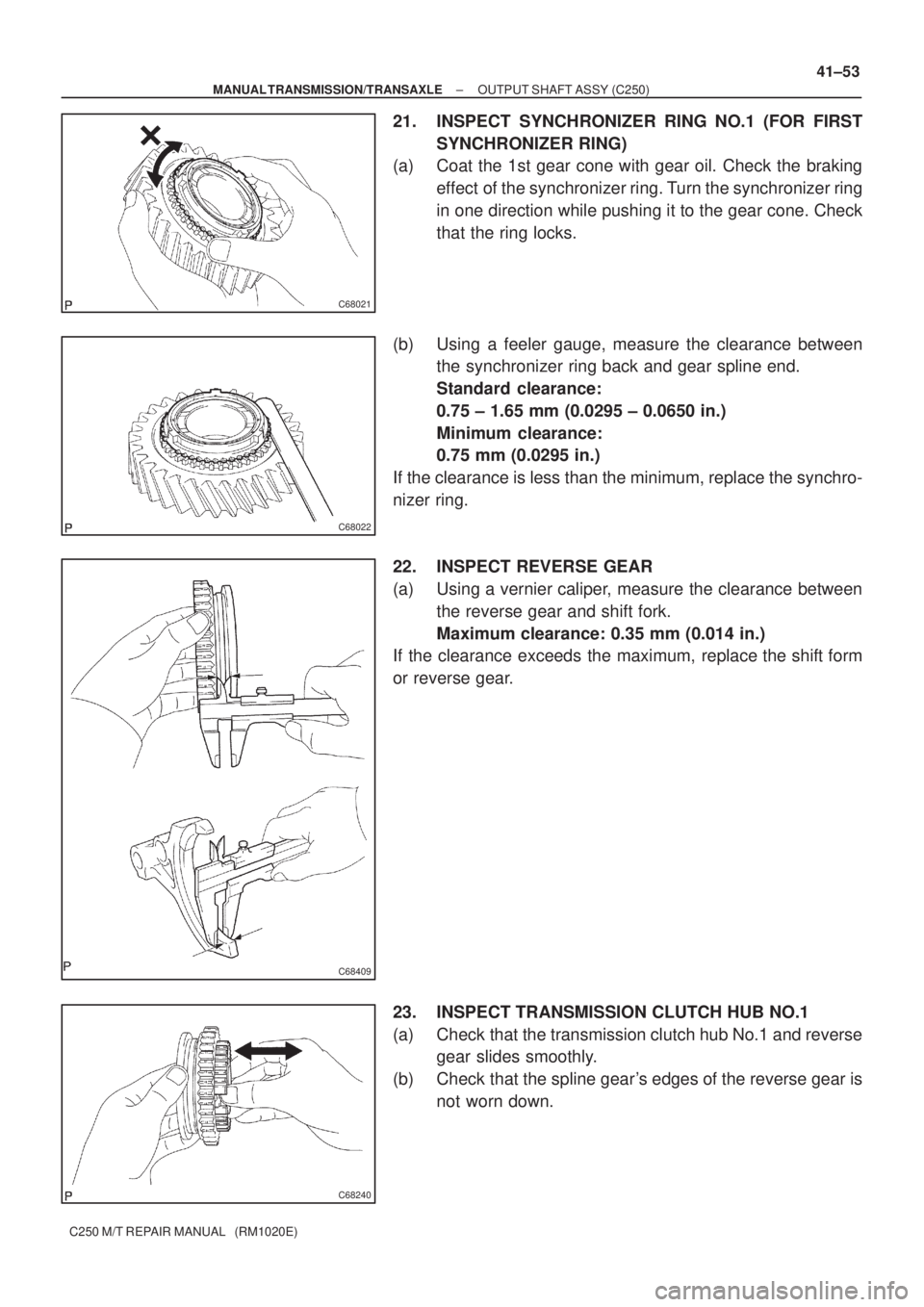
21. INSPECT SYNCHRONIZER RING NO.1 (FOR FIRST
SYNCHRONIZER RING)
(a) Coat the 1st gear cone with gear oil. Check the braking
effect of the synchronizer ring. Turn the synchronizer ring
in one direction while pushing it to the gear cone. Check
that the ring locks.
(b) Using a feeler gauge, measure the clearance between
the synchronizer ring back and gear spline end.
Standard clearance:
0.75 ± 1.65 mm (0.0295 ± 0.0650 in.)
Minimum clearance:
0.75 mm (0.0295 in.)
If the clearance is less than the minimum, replace the synchro-
nizer ring.
22. INSPECT REVERSE GEAR
(a) Using a vernier caliper, measure the clearance between
the reverse gear and shift fork.
Maximum clearance: 0.35 mm (0.014 in.)
If the clearance exceeds the maximum, replace the shift form
or reverse gear.
23. INSPECT TRANSMISSION CLUTCH HUB NO.1
(a) Check that the transmission clutch hub No.1 and reverse
gear slides smoothly.
(b) Check that the spline gear's edges of the reverse gear is
not worn down.
Page 3521 of 5135
C68241
C68014
C68013
C68012
C68310
41±54
± MANUAL TRANSMISSION/TRANSAXLEOUTPUT SHAFT ASSY (C250)
C250 M/T REPAIR MANUAL (RM1020E)
24. INSTALL REVERSE GEAR
(a) Coat the reverse gear with gear oil, install it to the trans-
mission clutch hub No.1.
HINT:
Do not set the reverse gear and transmission clutch hub No.1
in incorrect orientation.
(b) Install the 3 synchromesh shifting key springs and 3 syn-
chromesh shifting keys.
25. INSTALL 1ST GEAR THRUST WASHER PIN OR BALL
(a) Coat the 1st gear thrust washer pin or ball with gear oil,
install it to the output shaft.
26. INSTALL 1ST GEAR THRUST WASHER
(a) Coat the 1st gear thrust washer with gear oil, install it to
the output shaft.
27. INSTALL 1ST GEAR NEEDLE ROLLER BEARING
(a) Coat the 1st gear needle roller bearing with gear oil, install
it to the output shaft.
28. INSTALL 1ST GEAR
(a) Coat the 1st gear with gear oil, install it to the output shaft.
Page 3522 of 5135
C68311
C80547
SST
C68244
C68246
D30552
± MANUAL TRANSMISSION/TRANSAXLEOUTPUT SHAFT ASSY (C250)
41±55
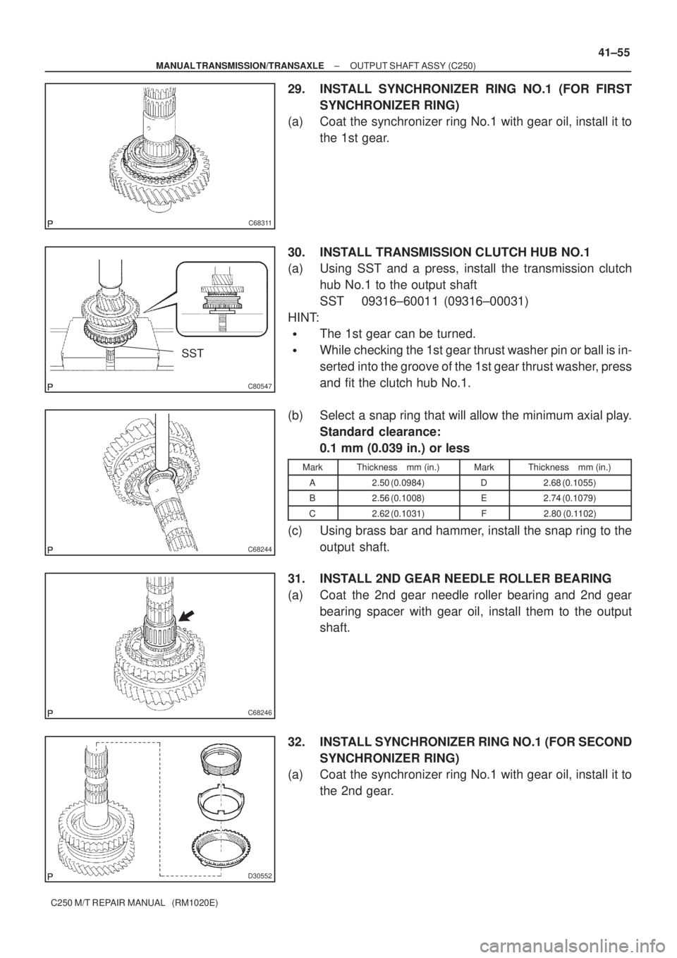
C250 M/T REPAIR MANUAL (RM1020E)
29. INSTALL SYNCHRONIZER RING NO.1 (FOR FIRST
SYNCHRONIZER RING)
(a) Coat the synchronizer ring No.1 with gear oil, install it to
the 1st gear.
30. INSTALL TRANSMISSION CLUTCH HUB NO.1
(a) Using SST and a press, install the transmission clutch
hub No.1 to the output shaft
SST 09316±60011 (09316±00031)
HINT:
�The 1st gear can be turned.
�While checking the 1st gear thrust washer pin or ball is in-
serted into the groove of the 1st gear thrust washer, press
and fit the clutch hub No.1.
(b) Select a snap ring that will allow the minimum axial play.
Standard clearance:
0.1 mm (0.039 in.) or less
MarkThickness mm (in.)MarkThickness mm (in.)
A2.50 (0.0984)D2.68 (0.1055)
B2.56 (0.1008)E2.74 (0.1079)
C2.62 (0.1031)F2.80 (0.1102)
(c) Using brass bar and hammer, install the snap ring to the
output shaft.
31. INSTALL 2ND GEAR NEEDLE ROLLER BEARING
(a) Coat the 2nd gear needle roller bearing and 2nd gear
bearing spacer with gear oil, install them to the output
shaft.
32. INSTALL SYNCHRONIZER RING NO.1 (FOR SECOND
SYNCHRONIZER RING)
(a) Coat the synchronizer ring No.1 with gear oil, install it to
the 2nd gear.
Page 3523 of 5135
C68248
C80548
SST
C68005
C82013
SST
C82014
SST
41±56
± MANUAL TRANSMISSION/TRANSAXLEOUTPUT SHAFT ASSY (C250)
C250 M/T REPAIR MANUAL (RM1020E)
33. INSTALL 2ND GEAR
(a) Coat the 2nd gear with gear oil, install it to the output
shaft.
34. INSTALL 3RD DRIVEN GEAR
(a) Using SST and a press, install the 3rd driven gear to the
output shaft.
SST 09950±00020
35. INSTALL OUTPUT GEAR SPACER
(a) Install the output gear spacer to the output shaft.
36. INSTALL 4TH DRIVEN GEAR
(a) Using SST and a press, 4th driven gear to the output
shaft.
SST 09612±22011
37. INSTALL OUTPUT SHAFT REAR BEARING
(a) Using SST and a press, install the output shaft rear bear-
ing to the output shaft.
SST 09612±22011