Page 3530 of 5135
C67828
C67829
C67830
41±42
± MANUAL TRANSMISSION/TRANSAXLEINPUT SHAFT ASSY (C250)
C250 M/T REPAIR MANUAL (RM1020E)
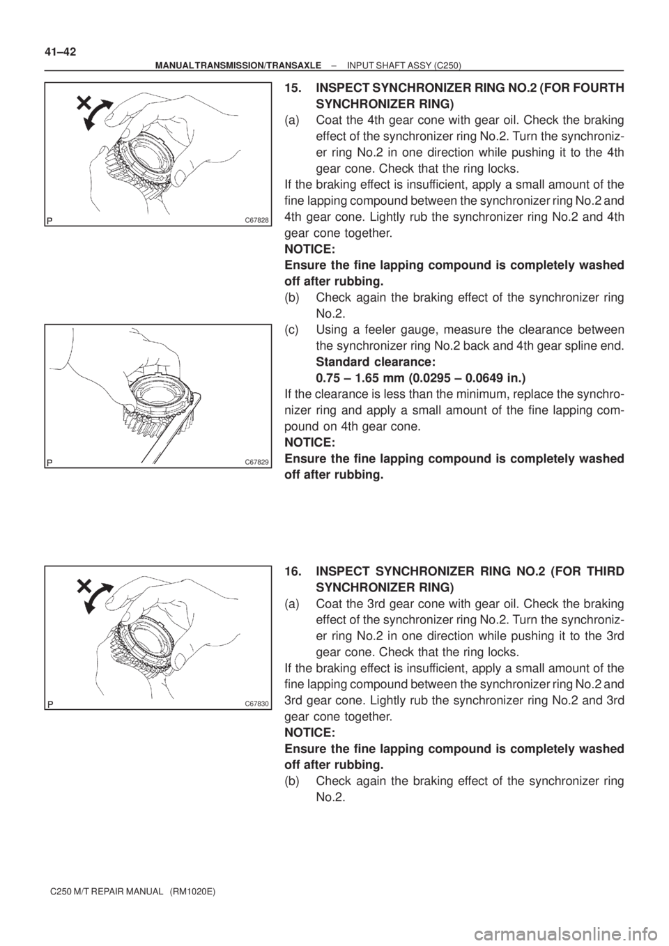
15. INSPECT SYNCHRONIZER RING NO.2 (FOR FOURTH
SYNCHRONIZER RING)
(a) Coat the 4th gear cone with gear oil. Check the braking
effect of the synchronizer ring No.2. Turn the synchroniz-
er ring No.2 in one direction while pushing it to the 4th
gear cone. Check that the ring locks.
If the braking effect is insufficient, apply a small amount of the
fine lapping compound between the synchronizer ring No.2 and
4th gear cone. Lightly rub the synchronizer ring No.2 and 4th
gear cone together.
NOTICE:
Ensure the fine lapping compound is completely washed
off after rubbing.
(b) Check again the braking effect of the synchronizer ring
No.2.
(c) Using a feeler gauge, measure the clearance between
the synchronizer ring No.2 back and 4th gear spline end.
Standard clearance:
0.75 ± 1.65 mm (0.0295 ± 0.0649 in.)
If the clearance is less than the minimum, replace the synchro-
nizer ring and apply a small amount of the fine lapping com-
pound on 4th gear cone.
NOTICE:
Ensure the fine lapping compound is completely washed
off after rubbing.
16. INSPECT SYNCHRONIZER RING NO.2 (FOR THIRD
SYNCHRONIZER RING)
(a) Coat the 3rd gear cone with gear oil. Check the braking
effect of the synchronizer ring No.2. Turn the synchroniz-
er ring No.2 in one direction while pushing it to the 3rd
gear cone. Check that the ring locks.
If the braking effect is insufficient, apply a small amount of the
fine lapping compound between the synchronizer ring No.2 and
3rd gear cone. Lightly rub the synchronizer ring No.2 and 3rd
gear cone together.
NOTICE:
Ensure the fine lapping compound is completely washed
off after rubbing.
(b) Check again the braking effect of the synchronizer ring
No.2.
Page 3531 of 5135
C67831
C67843
C67842
C67833
± MANUAL TRANSMISSION/TRANSAXLEINPUT SHAFT ASSY (C250)
41±43
C250 M/T REPAIR MANUAL (RM1020E)
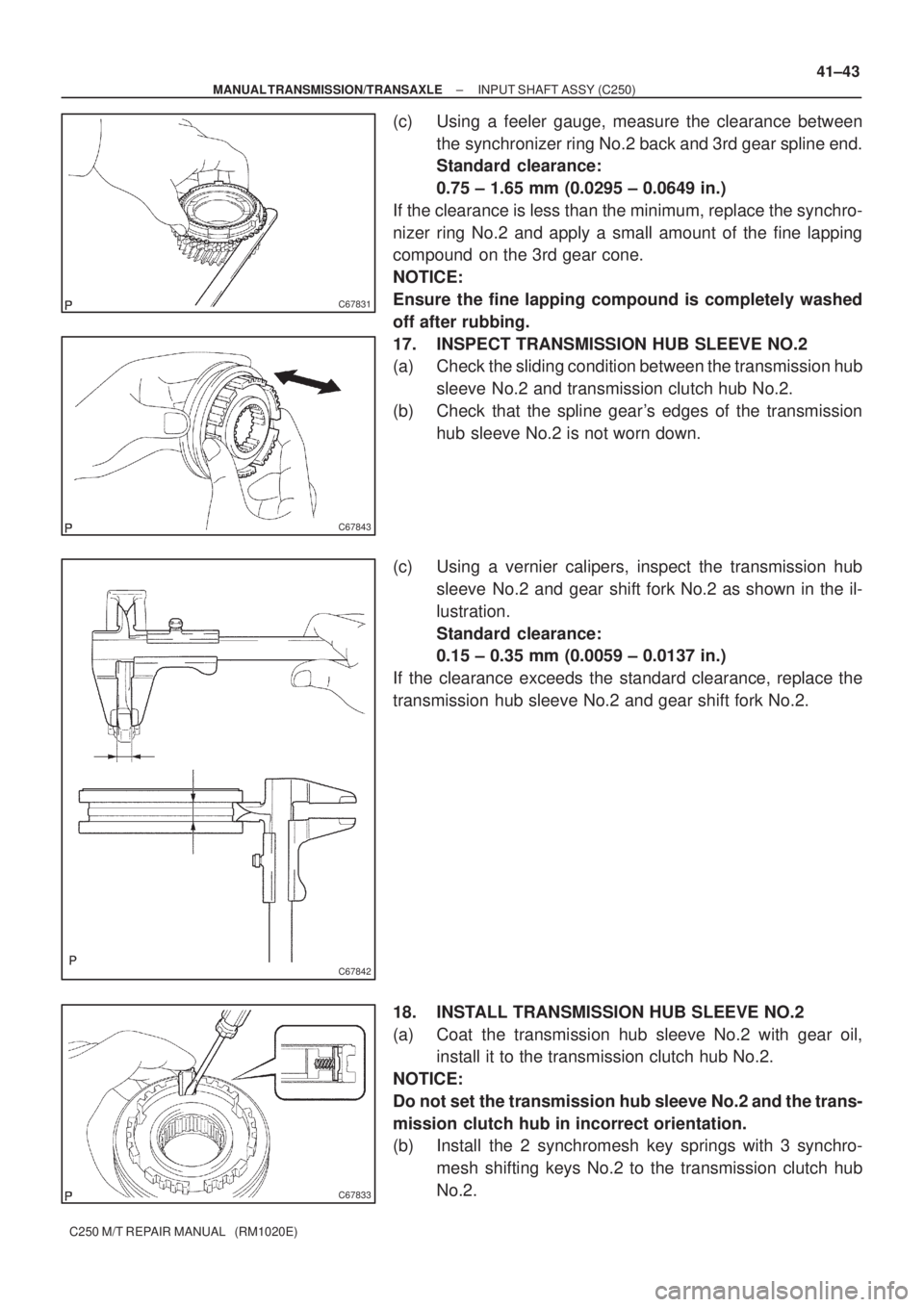
(c) Using a feeler gauge, measure the clearance between
the synchronizer ring No.2 back and 3rd gear spline end.
Standard clearance:
0.75 ± 1.65 mm (0.0295 ± 0.0649 in.)
If the clearance is less than the minimum, replace the synchro-
nizer ring No.2 and apply a small amount of the fine lapping
compound on the 3rd gear cone.
NOTICE:
Ensure the fine lapping compound is completely washed
off after rubbing.
17. INSPECT TRANSMISSION HUB SLEEVE NO.2
(a) Check the sliding condition between the transmission hub
sleeve No.2 and transmission clutch hub No.2.
(b) Check that the spline gear's edges of the transmission
hub sleeve No.2 is not worn down.
(c) Using a vernier calipers, inspect the transmission hub
sleeve No.2 and gear shift fork No.2 as shown in the il-
lustration.
Standard clearance:
0.15 ± 0.35 mm (0.0059 ± 0.0137 in.)
If the clearance exceeds the standard clearance, replace the
transmission hub sleeve No.2 and gear shift fork No.2.
18. INSTALL TRANSMISSION HUB SLEEVE NO.2
(a) Coat the transmission hub sleeve No.2 with gear oil,
install it to the transmission clutch hub No.2.
NOTICE:
Do not set the transmission hub sleeve No.2 and the trans-
mission clutch hub in incorrect orientation.
(b) Install the 2 synchromesh key springs with 3 synchro-
mesh shifting keys No.2 to the transmission clutch hub
No.2.
Page 3532 of 5135
C67823
C67834
C82010
Key Position
For 3rd gear
C80563
SST
C67837
41±44
± MANUAL TRANSMISSION/TRANSAXLEINPUT SHAFT ASSY (C250)
C250 M/T REPAIR MANUAL (RM1020E)
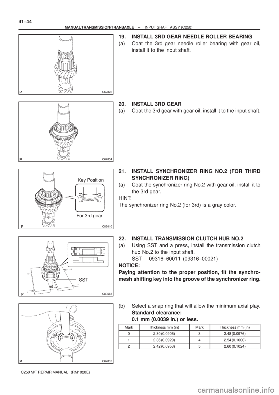
19. INSTALL 3RD GEAR NEEDLE ROLLER BEARING
(a) Coat the 3rd gear needle roller bearing with gear oil,
install it to the input shaft.
20. INSTALL 3RD GEAR
(a) Coat the 3rd gear with gear oil, install it to the input shaft.
21. INSTALL SYNCHRONIZER RING NO.2 (FOR THIRD
SYNCHRONIZER RING)
(a) Coat the synchronizer ring No.2 with gear oil, install it to
the 3rd gear.
HINT:
The synchronizer ring No.2 (for 3rd) is a gray color.
22. INSTALL TRANSMISSION CLUTCH HUB NO.2
(a) Using SST and a press, install the transmission clutch
hub No.2 to the input shaft.
SST 09316±60011 (09316±00021)
NOTICE:
Paying attention to the proper position, fit the synchro-
mesh shifting key into the groove of the synchronizer ring.
(b) Select a snap ring that will allow the minimum axial play.
Standard clearance:
0.1 mm (0.0039 in.) or less.
MarkThickness mm (in)MarkThickness mm (in)
02.30 (0.0906)32.48 (0.0976)
12.36 (0.0929)42.54 (0.1000)
22.42 (0.0953)52.60 (0.1024)
Page 3533 of 5135
D30573
Key Position
For 4th gear
C80560
C80564
C80565
SST
C80566
± MANUAL TRANSMISSION/TRANSAXLEINPUT SHAFT ASSY (C250)
41±45
C250 M/T REPAIR MANUAL (RM1020E)
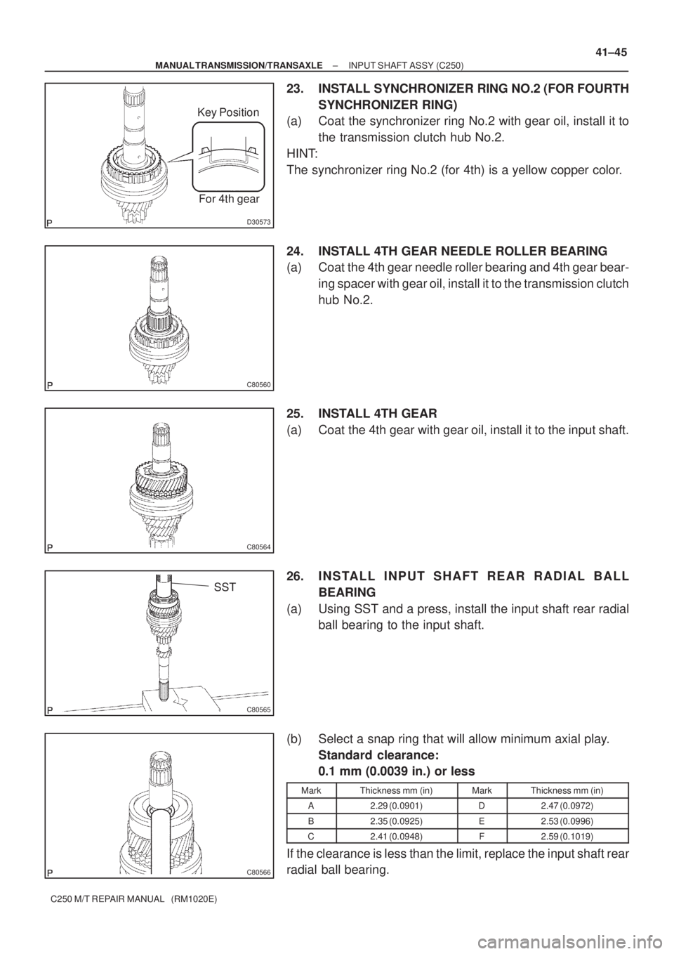
23. INSTALL SYNCHRONIZER RING NO.2 (FOR FOURTH
SYNCHRONIZER RING)
(a) Coat the synchronizer ring No.2 with gear oil, install it to
the transmission clutch hub No.2.
HINT:
The synchronizer ring No.2 (for 4th) is a yellow copper color.
24. INSTALL 4TH GEAR NEEDLE ROLLER BEARING
(a) Coat the 4th gear needle roller bearing and 4th gear bear-
ing spacer with gear oil, install it to the transmission clutch
hub No.2.
25. INSTALL 4TH GEAR
(a) Coat the 4th gear with gear oil, install it to the input shaft.
26. INSTALL INPUT SHAFT REAR RADIAL BALL
BEARING
(a) Using SST and a press, install the input shaft rear radial
ball bearing to the input shaft.
(b) Select a snap ring that will allow minimum axial play.
Standard clearance:
0.1 mm (0.0039 in.) or less
MarkThickness mm (in)MarkThickness mm (in)
A2.29 (0.0901)D2.47 (0.0972)
B2.35 (0.0925)E2.53 (0.0996)
C2.41 (0.0948)F2.59 (0.1019)
If the clearance is less than the limit, replace the input shaft rear
radial ball bearing.
Page 3547 of 5135
C67656
C67657
D30546
D30547
C67644
± MANUAL TRANSMISSION/TRANSAXLEMANUAL TRANSAXLE ASSY (C250)
41±15
C250 M/T REPAIR MANUAL (RM1020E)
38. REMOVE DIFFERENTIAL CASE ASSY
(a) Remove the differential case assy from the front transaxle
case.
39. REMOVE MANUAL TRANSAXLE CASE RECEIVER
(a) Remove the bolt and manual transaxle case receiver from
the front transaxle case.
40. REMOVE REVERSE RESTRICT PIN ASSY
(a) Using a hexagon wrench, remove the reverse restrict pin
plug from the manual transmission case.
(b) Using a pin punch (� 5 mm) and hammer, drive out the
slotted spring pin and reverse restrict pin assy from the
manual transmission case.
41. REMOVE OIL RECEIVER PIPE NO.1 (MTM)
(a) Remove the bolt and oil receiver pipe No.1 from the
manual transmission case.
NOTICE:
Be careful not to damage the oil receiver pipe No.1.
Page 3548 of 5135
C80374
C67658
C67659
C81783
SST
C81783
SST
41±16
± MANUAL TRANSMISSION/TRANSAXLEMANUAL TRANSAXLE ASSY (C250)
C250 M/T REPAIR MANUAL (RM1020E)
42. REMOVE OIL RECEIVER PIPE NO.2 (MTM)
(a) Remove the bolt and oil receiver pipe No.2 from the
manual transmission case.
NOTICE:
Be careful not to damage the oil receiver pipe No.2.
43. REMOVE BEARING LOCK PLATE
(a) Remove the bolt and bearing lock plate from the front
transaxle case.
44. REMOVE TRANSMISSION MAGNET
(a) Remove the transmission magnet from the front transaxle
case.
45. REMOVE INPUT SHAFT FRONT BEARING
(a) Using SST, remove the input shaft front bearing from the
front transaxle case.
SST 09612±65014 (09612±01050, 09612±01060)
46. REMOVE FRONT TRANSAXLE CASE OIL SEAL
(a) Using SST, remove the front transaxle case oil seal from
the front transaxle case.
SST 09612±65014 (09612±01040, 09612±01050)
Page 3549 of 5135
C82141
SST
C67719
C81785
SST
C82145
SST
C81789
SST
± MANUAL TRANSMISSION/TRANSAXLEMANUAL TRANSAXLE ASSY (C250)
41±17
C250 M/T REPAIR MANUAL (RM1020E)
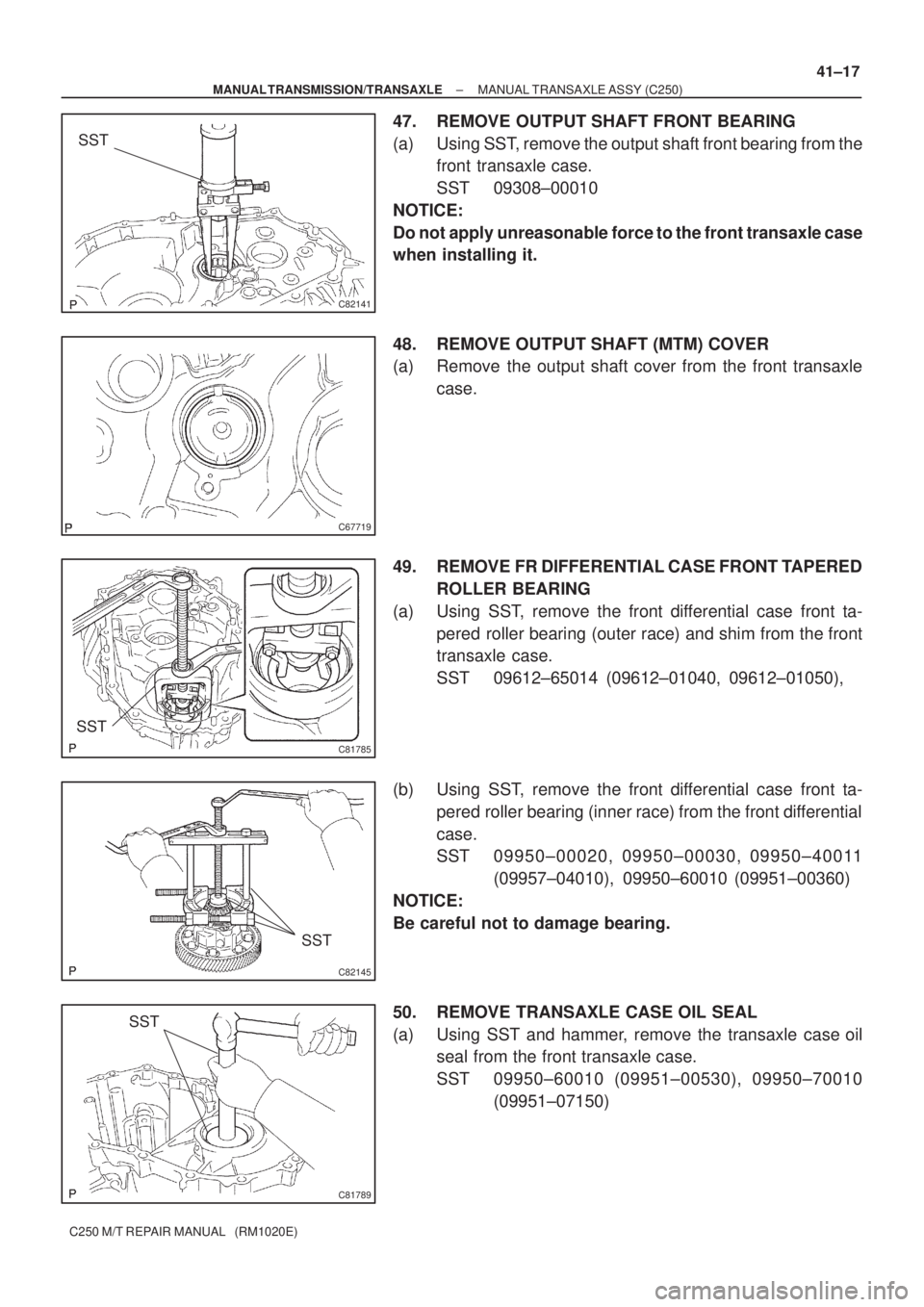
47. REMOVE OUTPUT SHAFT FRONT BEARING
(a) Using SST, remove the output shaft front bearing from the
front transaxle case.
SST 09308±00010
NOTICE:
Do not apply unreasonable force to the front transaxle case
when installing it.
48. REMOVE OUTPUT SHAFT (MTM) COVER
(a) Remove the output shaft cover from the front transaxle
case.
49. REMOVE FR DIFFERENTIAL CASE FRONT TAPERED
ROLLER BEARING
(a) Using SST, remove the front differential case front ta-
pered roller bearing (outer race) and shim from the front
transaxle case.
SST 09612±65014 (09612±01040, 09612±01050),
(b) Using SST, remove the front differential case front ta-
pered roller bearing (inner race) from the front differential
case.
SST 09950±00020, 09950±00030, 09950±40011
(09957±04010), 09950±60010 (09951±00360)
NOTICE:
Be careful not to damage bearing.
50. REMOVE TRANSAXLE CASE OIL SEAL
(a) Using SST and hammer, remove the transaxle case oil
seal from the front transaxle case.
SST 09950±60010 (09951±00530), 09950±70010
(09951±07150)
Page 3550 of 5135
C81788
SST
C82144
SST
C81787
SST
D30571
SST
C67848
41±18
± MANUAL TRANSMISSION/TRANSAXLEMANUAL TRANSAXLE ASSY (C250)
C250 M/T REPAIR MANUAL (RM1020E)
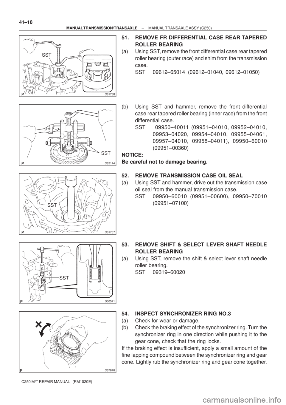
51. REMOVE FR DIFFERENTIAL CASE REAR TAPERED
ROLLER BEARING
(a) Using SST, remove the front differential case rear tapered
roller bearing (outer race) and shim from the transmission
case.
SST 09612±65014 (09612±01040, 09612±01050)
(b) Using SST and hammer, remove the front differential
case rear tapered roller bearing (inner race) from the front
differential case.
SST 09950±40011 (09951±04010, 09952±04010,
09953±04020, 09954±04010, 09955±04061,
09957±04010, 09958±04011), 09950±60010
(09951±00360)
NOTICE:
Be careful not to damage bearing.
52. REMOVE TRANSMISSION CASE OIL SEAL
(a) Using SST and hammer, drive out the transmission case
oil seal from the manual transmission case.
SST 09950±60010 (09951±00600), 09950±70010
(09951±07100)
53. REMOVE SHIFT & SELECT LEVER SHAFT NEEDLE
ROLLER BEARING
(a) Using SST, remove the shift & select lever shaft needle
roller bearing.
SST 09319±60020
54. INSPECT SYNCHRONIZER RING NO.3
(a) Check for wear or damage.
(b) Check the braking effect of the synchronizer ring. Turn the
synchronizer ring in one direction while pushing it to the
gear cone, check that the ring locks.
If the braking effect is insufficient, apply a small amount of the
fine lapping compound between the synchronizer ring and gear
cone. Lightly rub the synchronizer ring and gear cone together.